A High-Temperature Superconducting Wideband Bandpass Filter at the L Band for Radio Astronomy
Xinyu Zhu, Jianbin Li, Boyu Lu, Bin Wei, Yifan Jiang, Linan Jiang, and Chao Hu
1 National Astronomical Observatories, Chinese Academy of Sciences, Beijing 100101, China; lijb@bao.ac.cn
2 University of Chinese Academy of Sciences, Beijing 100049, China
3 State Key Laboratory of Low-Dimensional Quantum Physics, Department of Physics, Tsinghua University, Beijing 100084, China
Abstract In order to ensure the normal operation of radio astronomy observations, an extremely sensitive receiver system needs to be equipped in front of the large radio telescope.An 8-pole wideband high-temperature superconducting(HTS) filter using a Coplanar Spiral Resonator Structure with a passband of 1160∼1670 MHz is developed to suppress strong radio interference.The filter is fabricated on a 36 mm×14 mm YBCO HTS film, which is deposited on a 0.5 mm thick MgO substrate.The minimum insertion loss measured in the liquid nitrogen temperature region is 0.03 dB, and the first parasitic passband appears at 2600 MHz.The measured results are in good agreement with the simulations.The filter can be used in radio telescope receivers for the observation of neutral hydrogen and pulsars, as well as in high-sensitivity satellite navigation instruments.
Key words: instrumentation: detectors – techniques: radar astronomy – telescopes
1.Introduction
The L-band is an essential frequency band for satellite navigation, satellite communications, and radio astronomy observations.It covers various active radio services, including the radio satellite navigation and positioning service allocated by the International Telecommunication Union (ITU)(ITU 2020), the emission spectrum of neutral hydrogen, the molecular spectrum of hydroxyl groups in radio astronomy,etc.
However, there exists strong radio interference from Distance Measuring Equipment (DME) and terrestrial services signals, such as mobile communication on both sides of the band.The signals from satellite and astronomical observation are much weaker than the interference,resulting in undesirable nonlinear intermodulation distortion.Besides, the distortion products in the useful band, which cannot be filtered out, will significantly raise the noise floor of the system and drown out the useful signal.Therefore, the filter is one of the essential components in high-sensitivity receiver systems.It is necessary to insert a filter before the first-stage LNA to prevent receivers from saturation.
Since the discovery of yttrium-barium-copper-oxygen (Y–Ba–Cu–O) oxide superconductor materials, the superconducting transition temperature has been raised to the liquid nitrogen temperature region (70 K), which is easier to achieve.The surface resistance of the high-temperature superconducting(HTS)film at RF is 2–3 mag orders lower than that of copper,so the losses are negligible.Consequently, it can be used to make HTS filters with extremely low insertion loss,steep skirt slope, and high out-of-band rejection required by highsensitivity receivers.
Narrowband HTS filters have been extensively used in mobile communications, radar detection, and radio astronomy observation(Zhang et al.2004,2005;Zhou et al.2005).At the beginning of the 21st century, an eight-pole narrowband HTS filter with an insertion loss of 0.3 dB, is developed to improve the observation of pulsars at the Jodrell Bank Observatory(JBO), UK by suppressing the substantial signal interference from TV on both sides of the Ultra High Frequency(UHF)band (Zhou et al.2005).
In recent years, the demand for wideband bandpass filters has also been increasing (Li et al.2003; Huang 2005; Zhang et al.2007,2006).In traditional theory,a wideband filter means the resonator coupling strength is required to be strong.The coupling coefficients will appear inevitable deviation based on the design theory of the Chebyshev prototype over the bandwidth of 20%, which brings a huge challenge to the design.A set of design approaches for wideband filters are proposed to solve the problem, consisting of Multilayer liquid crystal polymer technology (Hao & Hong 2009), Stepped Impedance Resonator (SIR) structure, parallel-coupled microstrip lines,and Defected Ground Structure(DGS),but there are limitations on the fabrication and application.
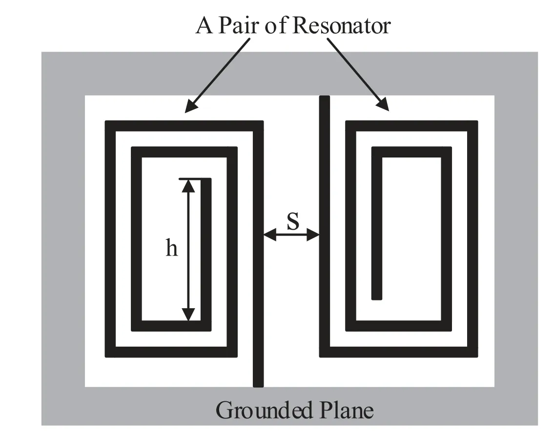
Figure 1.The configuration of the Coplanar Spiral Resonator Structure.
In addition, various novel configurations of resonators are developed to construct wideband filters by using Inter-digital Capacitor (IDC) Structure (Yu et al.2009), Double-Surface Coplanar Waveguide (CPW) Structure (Xu et al.2013), Coplanar Spiral Resonator Structure (CSRS) (Shang et al.2019), etc.In 2009,a 12-pole wideband HTS filter with a bandwidth of 38%was proposed for the Miyun 50 m radio astronomy telescope to provide a reliable guarantee for the regular operation of astronomical observation and deep space exploration.The resonators using a configuration of IDC combined with a hairpin-like structure can generate strong coupling and push its second harmonic upwards(Yu et al.2009).A novel CSRS with a compact grounded quarterwavelength spiral resonator is developed based on the CPW structure (Shang et al.2019).It can generate strong internal coupling between adjacent resonators,and the undesirable resonant mode is far away from the center frequency,providing a solution to the compact wideband filter at a low frequency.
In this paper, an 8-pole HTS filter with a passband of 1160∼1670 MHz is developed based on the CSRS.The measured responses show that the filter has a 0.03 dB minimum insertion loss with a bandwidth of 36%, and the return loss is better than −17 dB.The measurements show excellent performance, basically consistent with the simulations.
2.Resonator Design
2.1.Resonant Modes Analysis and Structure Design
Refrigeration units,which carry filter and Low Noise Amplifier(LNA)cascade systems, are widely applied in large radio telescope receivers to reduce the noise figure (Liu et al.2021).The miniaturization of the filter contributes to more space margins.Using spiral or folded resonators is helpful for miniaturization,but the coupling coefficient is not strong enough to construct wideband filters(Ma et al.2006).The CSRS proposes a solution.Figure 1 shows the configuration of the resonator pair designed by the CSRS.The electric field is densely distributed on both sides of the transmission line, similar to the CPW structure.Whereas,the grounded stub between the adjacent resonators in the CSRS is removed, which means a more muscular coupling strength.The metal strips bend into a spiral circuit, whose ends extend to the ground,forming quarter-wavelength resonators.No undesirable resonant modes appear during the simulation.

Figure 2.The layers of the Coplanar Spiral Resonator Structure.
By using the full-wave electromagnetic simulation software Sonnet (Sonnet Software 2009), we can determine the detailed structures of a single resonator.The resonant frequency will decrease with the increasing length of the circuit.For a compact filter that works in low frequency, we optimize the resonator structure by balancing the spiral turns with the width of the entire resonator until the resonant peak is equal to the filter center frequency (f=fc).One end of the circuit extends to the surrounding ground plane with a length of 1.5 mm,the other is adjustable to compensate for the frequency offset.
2.2.Structure Layers
Figure 2 illustrates the layers of the CSRS structure.The circuit is etched on the HTS thin film deposited on the MgO substrate.Based on the electromagnetic resonant mode mentioned above, there exist two air layers on both sides of the dielectric substrate.H1represents the height of the air layer upon the substrate, and H2denotes the distance from the substrate to the ground.Simulation results indicate that the thickness of the air layers has an impact on the resonant frequency and coupling strength.As shown in Figure 3, the resonant frequency rises with increasing any two height parameters.When we keep H1constant, the growth rates decrease with the increase of H2, and vice versa.Besides, H2has a more significant impact on the frequency offset than H1,and the growth rates decrease when H2is over 2 mm.The coupling coefficient shows the same tendency.
Considering the heat dissipation combined with the entire size and the effect of H2is relatively weak, we choose 5 and 2 mm for H1and H2, respectively.The ultimate length of h is 2.2 mm.Every resonator is set to have the same linewidth of 0.1 mm due to processing and manufacturing convenience.Eventually, the single resonator is 2.2 mm×8.5 mm.
3.Filter Design
3.1.Resonator Coupling Design
One of the requirements for designing a wideband filter is realizing strong adjacent coupling (Hong 2011).The coupling coefficient M as a function of the width S between resonators,is defined as (1)

Figure 3.Left: The resonant frequency with different thicknesses of air.Right: Coupling coefficients of adjacent resonators with different thicknesses of air.
where f1and f2correspond to the lower and upper resonance peak frequencies, respectively.As the first step of our design,the ideal coupling coefficients of the filter pairs suitable for Chebyshev polynomials are calculated through the simulation software.Then we adjust the width S until the value of simulation M is equal to the ideal one.Considering the requirements of miniaturization and low insertion loss, an 8-pole filter with a return loss greater than 20 dB is derived.The coupling matrix is
where mi,j(i=1, 2,3, 4,5, 6,7;j=i+1)denotes the adjacent coupling.The external coupling coefficient qe,which is defined as the coupling strength of the input/output ports to the first resonator, can be conducted by (2)
where FBW is the fractional bandwidth,Qedenotes the external quality factor,which can be obtained by the center frequency fcand the corresponding group delay τ0as (3)
3.2.External Coupling Design
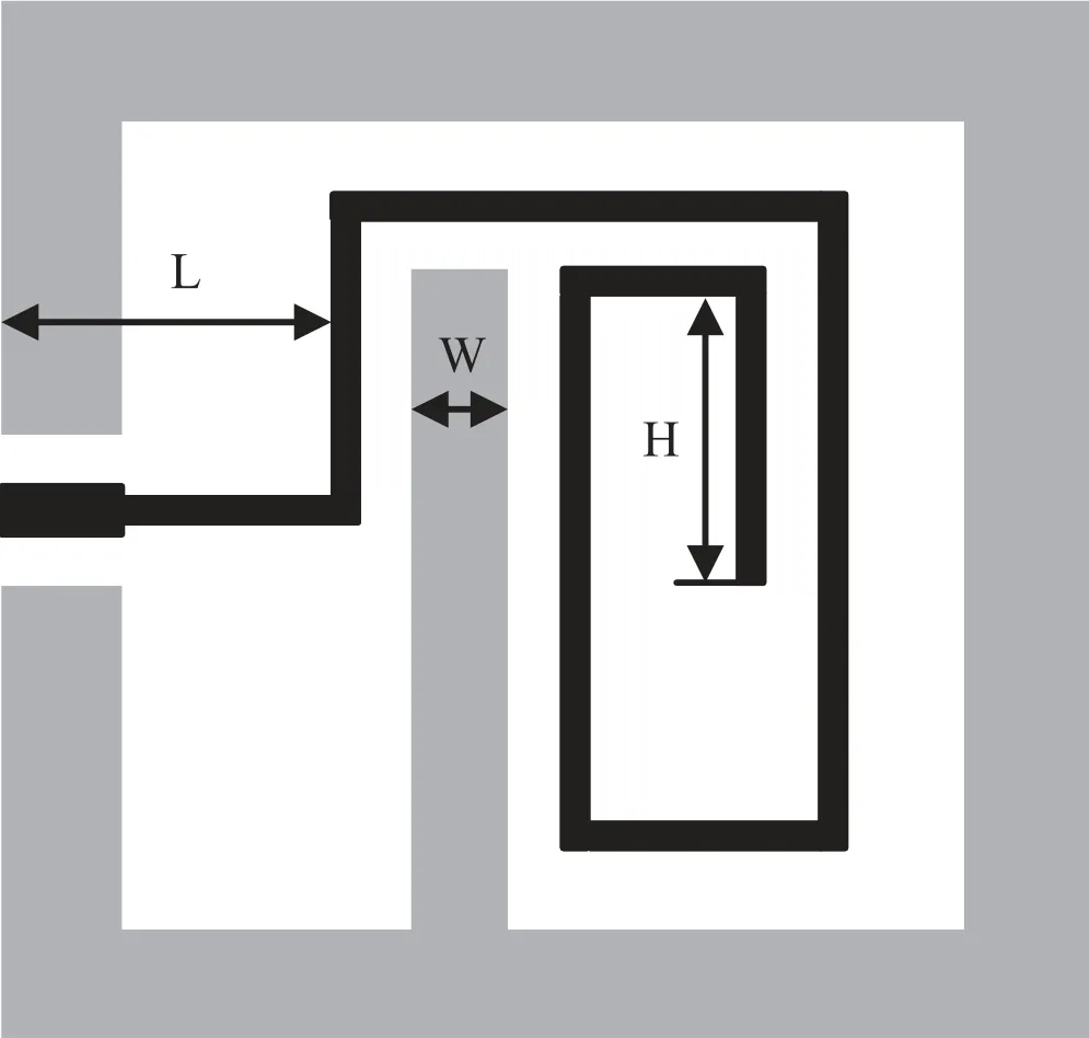
Figure 4.The configuration of the external coupling.
In traditional theory, there are two common structures for external coupling.Open-circuit coupled lines are widely applied in narrowband filters as a result of weak coupling strength.The tapped feed line structure proposed in Hong(2011), provides a strong coupling strength that can be employed in this design.The configuration of the external coupling is shown in Figure 4 (only one side).The input/output feed line is placed at the center of the substrate width for processing and manufacturing convenience.To realize 50 Ω impedance matching, the length and width of the feed line are selected as 2 mm and 0.48 mm, respectively.The input and output feed lines are directly connected to the end of the first resonator.In order to strengthen the external coupling and suppress undesirable resonance,an additional grounded stub is implemented in the first resonator.The external coupling can be adjusted by three parameters in this design:the width of the grounded stub W,the length of the vertical feed line to the edge of the ground plane L, and H.

Figure 5.The configuration of the entire filter (not to scale).(L12=0.44 mm, L23=0.8 mm, L34=1.02 mm, L45=0.92 mm).
Figure 5 depicts the layout of the entire filter.Every resonator has the same winding direction, which means adjacent resonator pairs have different coupling modes.Both of the two modes can realize strong coupling strength that reaches up to 0.55 and 0.65, respectively (dashed box in Figure 5).We combine resonator pairs with the external coupling part to form a complete filter.However, the simulation response seems not as expected.It is speculated that the extraction of narrowband coupling coefficients based on Chebyshev is not suitable for wideband filters.The optimization consists of narrowing the width of the first resonator pair (L12) and tuning the external coupling parameters.H0is adjusted to compensate for the frequency offset.Eventually,simulation results show excellent performance with 0.03 dB minimum insertion loss and better than −20 dB return loss.The first parasitic passband appears at 2700 MHz,approximately 1.9 times the center frequency.
4.Fabrication and Measurement
The filter is fabricated on a 500 nm thick YBCO thin film deposited on a 0.5 mm thick MgO substrate, of which the relative dielectric constant is taken to be 9.7.After standard photolithography and ion beam etching, the 36 mm×14 mm filter circuit is formed.Then we package it into a metal box to reduce radiation loss.Different from the traditional microstrip line structure, the substrate of CSRS does not directly contact the ground.As a result,we hollow out the bottom of the metal box and preserve a slot to support the substrate, as shown in Figure 2.The input and output feed lines are connected to the sub-miniature A (SMA) connector through the gold wire.The gold wire is combined with the circuit feed lines by Ultrasonic Molecular Bonding Machine.
As shown in Figure 6,the sealed metal box is mounted on a platform inside the Stirling cooler,with an associated computer that can be used to adjust the cooling temperature.After setting the cooling temperature to 65 K, the cooling system begins to create a vacuum and cool down, a process that takes approximately one hour.Prior to testing, we select the Agilent N5230C vector network analyzer (VNA) for this task and calibrate it.The first step involves connecting the calibration device with the VNA, the calibrator’s input port(Port A)links to Port 1 of the VNA, and the output port(Port B)connects to Port 2.When the calibrator’s red light illuminates, we wait for it to turn green, indicating a successful connection.The start and end frequencies can be set through the“Freq”button on the dashboard.In accordance with the test frequency requirements,the frequency range of the VNA is set from 300 MHz to 2 GHz.Afterward,press the“Cal”button on the VNA,select the E-Cal mode on the screen, choose the “2-Port Cal,” and initiate calibration.The calibrator can be disconnected after waiting for the system to auto-calibrate.
After the calibration,we connect the VNA with the reserved ports of the cryogenic cooling platform via the transmission line,with the input power set at −10dBm.The S-parameters of the filter can then be read from the screen.No tuning is implemented during the measurement.As depicted in Figure 7,the measured passband ranges from 1160 to 1674 MHz,corresponding to a bandwidth of 36%.The filter has a 0.03 dB minimum insertion loss and the return loss is better than−17 dB.The first spurious passband starts from 2600 MHz,which is a lower frequency range than that predicted by the simulation results.Figure 8 compares measured and simulated curves with different types of lines representing specific parameters.There is no obvious offset in the passband of the overall curve.The measured results show good agreement with the simulations.
In order to test the power stability and temperature variability of the filter, the S-parameters under different input power and refrigeration temperatures are measured shown in Figure 9.Input power changes have little impact on the filter in Figure 9 Left.However,as shown in Figure 9 Right,the rise in temperature will cause the deterioration of insertion loss and the deviation of the passband.The optimal response curve is reached when the temperature drops below 62k.Table 1 shows the comparison with other reported wideband filters.It can be seen that the filter using the CSRS offers a wider passband and minimal insertion loss.

Figure 6.The low-temperature test device and the fabricated filter circuit.
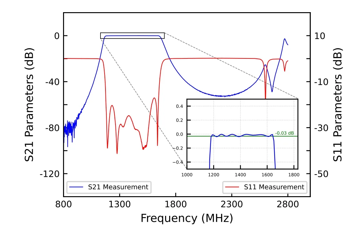
Figure 7.The measured S-parameters of the filter at 65 K.
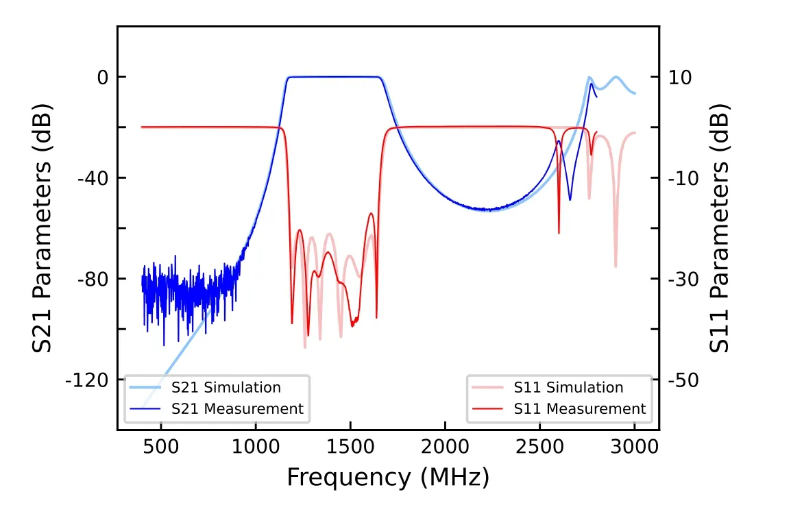
Figure 8.Comparison of measured and simulated results at 65 K.
5.Conclusions
In this paper, a Coplanar Spiral Resonator Structure is applied to design a wideband filter at the L band for radio astronomy.The filter is fabricated on a 36 mm×14 mm YBCO HTS film deposited on a 0.5 mm MgO substrate and shows excellent performance at 65 K.The filter has the advantage of compact configuration and high power handling capacity that can not only be applied in radio astronomical telescope receivers, but also in high-demand satellite navigation communication, radio signals monitoring, and other services.

Figure 9.Left: The comparison of different input power.Right: The comparison of different temperatures.

Table 1 Comparison with Other HTS Filters
Acknowledgments
This work was supported by the Science and Technology Project of Tibet Autonomous under grant XZ201901-GB-21,the National Natural Science Foundation of China under grant 11073027, and the Science and Technology Research and Development Program Project of China National Railway Group under grant P2021G011.
 Research in Astronomy and Astrophysics2023年11期
- Research in Astronomy and Astrophysics的其它文章
- Photometric and Spectroscopic Study of Two Low Mass Ratio Contact Binary Systems: CRTS J225828.7-121122 and CRTSJ030053.5+230139
- Injection Spectra of Different Species of Cosmic Rays from AMS-02, ACECRIS and Voyager-1
- The AIMS Site Survey
- Modified Masses and Parallaxes of Close Binary Systems: HD 39438
- Detecting HI Galaxies with Deep Neural Networks in the Presence of Radio Frequency Interference
- X-Ray Properties of PSR J1811-1925 by NuSTAR
