Direct Ion Beam Figuring Process and Rotational Measurement Method for Ultra-smooth Aspherical Surfaces of a 46.5nm Telescope
Weichen Gu, Jun Yu, Pengfeng Sheng, Qiaoyu Wu, Qiushi Huang, and Zhanshan Wang
1 Key Laboratory of Advanced Micro-structured Materials, Ministry of Education, Tongji University, Shanghai 200092, China; yujun_88831@tongji.edu.cn
2 Institute of Precision Optical Engineering, School of Physics Science and Engineering, Tongji University, Shanghai 200092, China
Abstract This paper describes a fabrication process for the hyperboloidal concave mirror of a 46.5 nm telescope.The 180 mm aperture hyperboloidal concave mirror and 70 mm aperture compensator are machined directly from chemical mechanical polishing of a spherical surface to a high-accuracy aspherical surface by ion beam figuring.The aspherical measurement method is the Dall null test.To minimize system errors in the measurement process,the rotational measurement method with six rotations is used in the null test.The results of the analysis for the ME(first solve the machined surface profile, then solve the system errors) and EM (first solve the system errors, then solve the machined surface profile) methods of calculation in the measurement are given.The ME method is a more accurate rotational test method, and the six rotations are appropriate for rotational measurements.After the figuring process, the hyperboloidal concave mirror surface profile reached 8.27 nm rms and the compensator surface profile is approximately 4 nm rms.The roughness of the hyperboloidal concave mirror is smooth to 0.160 nm rms.
Key words:Astronomical Instrumentation–Methods and Techniques–instrumentation:high angular resolution–telescopes
1.Introduction
There have been some satellites equipped with extreme ultraviolet (EUV) telescopes—for example, SPICE (SPICE Consortium et al.2020) and SDO-AIA (Cheimets et al.2009;Lemen et al.2011)—to perform various solar observations.However,there is no available equipment for probing the solar high transition region.Now, with the advance of EUV multilayers,it is possible to fabricate a 46.5 nm solar telescope to observe the solar high transition region with a bandwidth of less than 3 nm.A 46.5 nm telescope would be designed as a Ritchey–Chretien configuration with a field of view of 42′ and an imaging resolution of 6″.The primary mirror would be a hyperboloidal concave surface, with an aperture of 180 mm, a radius of 1164 mm, a conic coefficient of 1.40454, and a maximum asphericity of approximately 2 μm.Because the optical resolution of the 46.5 nm telescope is mainly influenced by the accuracy of the surface profile of machined reflectors and the optical collection efficiency,its limits are mainly set by the surface reflectivity, which, in turn, can be seriously degraded by surface roughness.Thus,a hyperboloidal concave mirror with sub-nanometer roughness (Solak et al.2001)(rms < 0.5 nm) and a nanometer-level surface profile error(rms < 10 nm) is a needed core optical element for an EUV telescope.
Needing a super smooth aspheric characteristic, the hyperboloidal concave mirror cannot be machined by classic optical fabrication methods.The computer controlled optical surfacing technology (Greenleaf 1980) is an optical fabrication method that can efficiently modify the surface profile (Jones et al.1990), including magnetorheological finishing (MRF) (Jacobs et al.1995),bonnet polishing(BP)(Lee et al.2010;Wang et al.2014), and ion beam figuring (IBF) (Allen & Keim 1989;Drueding et al.1995).MRF and BP are contact figuring methods, often used to form aspherical surfaces quickly.However, these contact methods can introduce subsurface damage, and the residual polishing slurry may easily lead to more surface roughness (Du et al.2021).IBF is a non-contact figuring technology,which can remove substrate material at the atomic level.IBF is performed under a vacuum without polishing contamination,and can achieve both superior surface profile accuracy and very low roughness (Chkhalo et al.2016,2017).Thus,IBF is an attractive choice as a final step to finishing the super smooth surface figuring for the hyperboloidal concave mirror.For higher machined surface accuracy,surface profile measurements of the hyperboloidal concave mirror should be conducted often during iterative IBF.Aspherical surface interferometry has the advantages of high precision and efficiency,and includes null test and non-null test methods.Non-null test methods often require some complex correction methods to compensate for system errors, such as partial null test and sub-aperture stitching interferometry(Liang et al.2022).Null test methods, such as Offner compensation(Offner 1963) and Dall compensation (Malacara 2007), conveniently correct the aspherical aberrations of the optical testing system using a compensation lens.The Dall compensation has only one compensator, and the entire optical path is less than for the others.Thus, the Dall compensation method has the advantages of fewer lenses and shorter optical path,and could be adopted in our measurements.However,this common null test may not fully satisfy the measurement demand with sub-nanometer accuracy due to errors in the reference surface profile, compensator surface profile, and residuals.For higher measurement accuracy, the rotational method (Evans et al.1996;Freimann et al.1999)can be used to reduce such an error in the interferometry.A combination of the null test and the rotational method is a good solution to balance efficiency and accuracy.In particular, the method of solving for the system errors in the machined surface, as well as the number of rotation times, also needs to be taken into consideration when solving for the machined surface profile by rotational measurement.In this work, a high precision hyperboloid concave mirror was fabricated by IBF and measured by the null compensation method.In Section 2,the direct figuring process of the hyperboloidal concave mirror from a spherical surface to an aspherical surface by IBF is described.In Section 3,a highprecision aspherical measurement method combining a rotational measurement and null compensation method is described.Also, the residual measurement errors of the two methods are analyzed with the goal of optimizing the fabrication flow.Section 4 deals with the efficient fabrication of the hyperboloid concave mirror using an optimized process and with the proposed subsequent measurement method.
2.Direct Figuring Process for Ultra-smooth Aspheric Surfaces
Because the surface roughness of a reflective mirror made of fused silica can be diminished using an ion beam etching process (Chkhalo et al.2014; He et al.2021) and because the fused silica has a low thermal expansion coefficient (Xie et al.2012), the hyperboloidal concave mirror substrate is made of fused silica.Specifically,this aspheric surface can be fabricated from the spherical surface directly based on IBF, and with an experimental etching depth of more than several hundred nanometers, it is possible to obtain an ultra-smooth surface efficiently (Barysheva et al.2013;Chkhalo et al.2016).Based on the null compensation method, this hyperboloidal concave mirror can be measured by a single lens null compensator.The single lens null compensator should therefore be fabricated first.Because the manufacturing accuracy of the null compensator can influence the aspherical surface directly, the single lens null compensator should also be machined by IBF.A flow chart of the direct figuring process is shown in Figure 1.The initial mirror surface is first machined by chemical mechanical polishing (CMP).The main purpose of CMP is to obtain super smooth surface with sub-nanometer roughness(initial surface roughness is 0.799 nm rms).Before the hyperboloidal concave mirror is fabricated, the null compensator is machined with nanometer surface accuracy.Thus, the spherical surface of the null compensator is machined to improve surface figure accuracy by iterative IBF.The null compensator is measured by rotational measurement to modify the machined surface profile.Then, the aspherical figuring is achieved by iterating several cycles to reach the null compensation measurement range.During the aspherical mirror measurement, the rotational measurement method combined with null compensation is applied.After the preliminary and precise iterative stages, the desired aspherical surface can be achieved.The surface roughness of the machined mirror is then scanned by atomic force microscopy (AFM) to compare the roughness before and after the IBF.
3.IBF Figuring and Surface Profile Rotational Measurement
The IBF was conducted using an ion beam device, SCIA trim200, with an radio frequency ion source (Ar), which contains XY axes for controlling the linear movement of the mounted mirror.The RF ion source is mounted on the Z-axis,and rotates through angle φ around the X-axis.The ion-beam source parameters can significantly affect the roughness(Chkhalo et al.2014).The initial ion-beam source working parameters are listed in Table 1.The etching rate is approximately proportional to the beam voltage.The selected beam voltage is 1500 V, which balances machining efficiency and machined surface roughness.
3.1.IBF Figuring and Calibration
Considering possible large sag deviation of the hyperboloidal concave mirror from the center to the edge, the IBF footprint and the angle etching compensation need to be calibrated accurately.For each measurement,the surface profile is used to produce a simulation result of the removal,where the amount of material removed at each point is determined using the dwell time algorithm.The amount of material removed at a point Z(x, y) in IBF can be expressed as a convolution of the removal function G(x, y) and the dwell timet(x,y):
The surface shape profile can be measured before machining,and the dwell time at each point is determined directly by the removal function.To obtain the exact removal function G(x,y),the IBF removal function is obtained by a single-point etching experiment and a Gaussian fit is performed to initialize the etching rate,as shown in Figure 2(a).The calibration of the IBF rate proceeds as follows:

Figure 1.Flow chart for direct figuring of the aspherical surface.
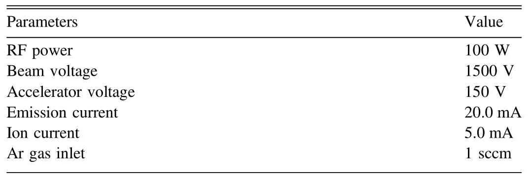
Table 1 Ion-beam Source Parameters
A.A wedge etching experiment is used to calibrate the etching rate with a linear fitting.During the wedge etching stage, the difference between the actual etching rate and the etching rate obtained by single point etching can cause a difference between the actual removal amount and the theoretically removal amount.As shown in Figure 2(b),through a linear fitting of the actual removal amount, the real etching rate can be obtained as the single point etching rate multiplied by the slope.
B.An angle etching experiment is performed to compensate the etching rate error caused by the slope of the surface.A correction matrix can be obtained in this experiment, and can be used to correct the etching rate at different positions on the surface, as shown in Figure 2(c).
3.2.Surface Figure Measurement and Analysis
The Dall null test is an aspherical measurement method requiring a high-precision compensator.The compensator should therefore be machined and measured before the hyperboloidal mirror is fabricated.The Dall null test configuration is shown in Figure 3, where the null test is conducted by a Zygo interferometer.The detailed design parameters of the null test are shown in Table 2.In our test optical path,we premanufactured the rod of a fixed length to calibrate the position of optical components in the test according to design.We measured the length of rod precisely using calipers, and the error is within 20 μm.The distance deviation can be converted to the errors in radius R and conic coefficient K according to Figure 4(a), and it is a trivial value (not more than 0.002%).From Figures 4(b) and (c), we can know that the wave front change due to the distance deviation can be offset by optimized radius R and conic coefficient K.The distance deviation can ultimately be translated into an adjustment value for the spacing between the primary and secondary mirrors in the system.It can also be observed from the designed system(Figure 4(d)) to system with optimized coefficients(Figure 4(e)) that the spot diagram has not been significantly affected.
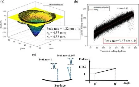
Figure 2.(a) Single point etching result and fitting.(b) Wedge etching result and fitting.(c) Angled etching result, showing that the etching rate at 8° of inclined position is 1.167 times that at 0°.
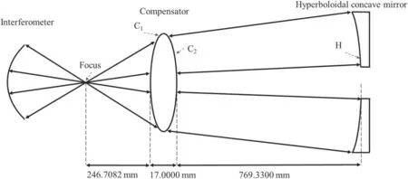
Figure 3.Optical layout of Dall compensator.
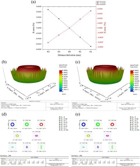
Figure 4.(a)The percentage errors of radius R and conic coefficient K caused by the distance deviation;(b)The wave front function of the primary mirror in designed position is 0.0117 λ (λ=632.8 nm) rms; (c) The wave front function of the primary mirror after optimized R=−1164.05212 and conic coefficient K=−1.40345(due to the distance deviation) is 0.0114 λ (λ=632.8 nm) rms; (d) The spot diagram of the designed system; (e) The spot diagram of the system with optimized distance from primary mirror to secondary mirror.
When the profile error is larger than several hundred nanometers, the preliminary figuring stage can be performed without considering measurement system errors, including mainly the reference surface profile error, the compensator surface profile error, and residual alignment errors.When the surface profile error is reduced to the nanometer level, the measurement system errors cannot be ignored.The measurement results include the surface profile error and the system errors, which can be analyzed by the reconstructed optical measurement model.The surface profile and position of these optical elements in the model need to be measured accurately.The reference spherical surface on the Zygo interferometry can be calibrated with a standard reflective mirror, and directly subtracted from the subsequent measurement result.Because it is difficult to measure the residual alignment errors of the null compensator during aspheric measurement, the measurement errors on the null compensator cannot be fully eliminated.
When the surface profile reaches nanometer level,rotational measurement methods are performed at a precise iterative stage, as shown in Figure 5(b).The rotational measurement method can separate the machined surface profile from the measurement wave front by rotating and averaging these measurement results (Evans & Kestner 1996).The rotational measurement is a better method for reducing the system errors;it directly simplifies the decomposition of various types of errors.At this stage, the measurement wave front can be expressed by W=E+M, where E is the sum of the system errors and M is the machined surface profile.For any circular aperture, the wave front can be expressed by Zernike polynomials:


Table 2 Optical Layout Parameters of Dall Compensator

The number of rotations and the calculating methods were researched as follows.As shown in Figure 5(a), at the beginning of the precise iterative stage, the N-angle averaging result by single measurement data is simulated.According to a principle is similar to that of Equations(7)and(8),the N-angle averaging result Tavg−Ncan be expressed as
In machining and rotational measurement, the difference between the calculated machined surface profile and the actual result M contains either the first two terms or the last two terms of Equation (9).The angular order of the term increases with the rotation number in Equation (9).Thus, the remaining accumulation of N× times angular-order terms can be derived from the comparison between different numbers of rotations(N-angle averaging).calculation method—i.e.,[Wi]EMmeans the EM method, and the square bracket means that several results are included.

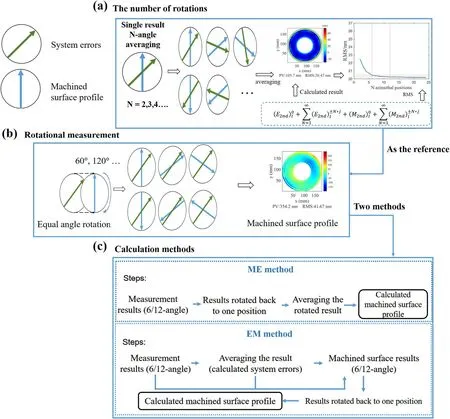
Figure 5.The figure assumes that the green arrow represents system errors and the blue arrow represents the machined surface profile.(a)By averaging the results of multiple rotations of a single measurement, the rms relation of the Nth term errors in the measurement is obtained, which provides a reference for the rotational measurement times.(b) The rotational measurement method is to rotate the machined surface profile (blue arrow)through six equal angles in practice, using the six results to obtain the machined surface profile with two calculation methods.(c) Two calculation methods: The ME method is which first calculates the machined surface profile and the EM method which first calculates the system errors.


The EM method is shown as the left side of Figure 6: the initial measurement results[Wi]EMat the six equally divided angles are rotated to the same marked position and averaged,which eliminates the additional wave front errors in the test results and leaving only the N order terms and the rotational symmetric terms.The image alignment of the calculation process relies on the markers on the mirror.The system errors EEMand the machined surface profileME′Mcan be calculated by:
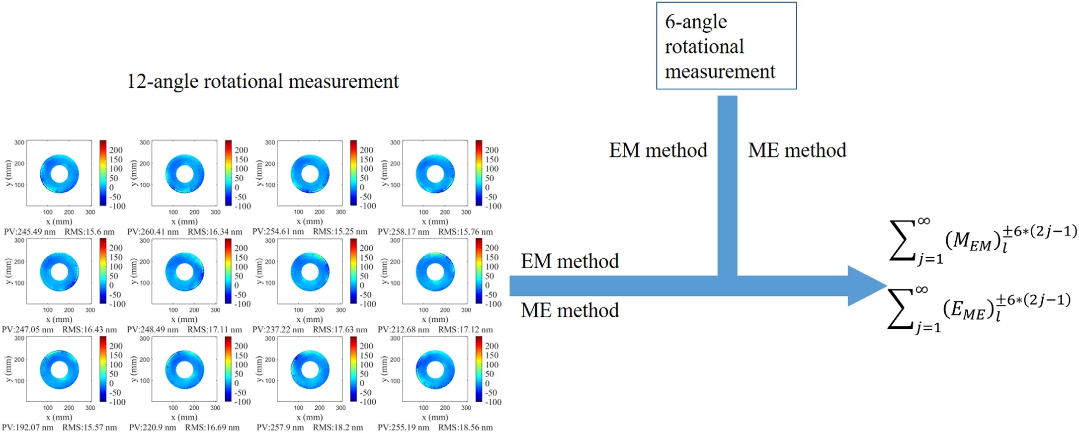
Figure 7.Schematic of the calculation of the 6 × (2j -1)order rotational terms.The process begins with a 12-angle rotational measurement with a rotation angle of 30°per rotation.The calculation of the sixth order angular terms is performed by subtracting the average results of the 6-time(obtained by taking the average of six rotations derived from the 12 rotations)and the 12-time rotational measurements,comparing the results in the ME method and the EM method.Then eliminating the rotational symmetric terms (k=0).This allows for the separate determination of the 6 × (2j -1) order rotational terms in two methods.
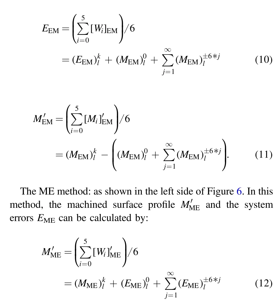
To evaluate which of the two methods is better, separating higher-order angular terms for comparing the methods is necessary.The 12-angle rotational measurement is carried out after the 6-angle rotational measurement,as shown in Figure 7,according to each of the two methods, and the calculated system errors of the EM method in the 6-angle rotational measurement can then be obtained (Equation (14) below):
and the calculated machined surface profile of the ME method in the 12-angle rotational measurement can then be obtained(Equation (15) below):
The calculated machined surface profile and system errors between the 6-angle and 12-angle rotational measurements give the 6 × (2j-1) order rotational terms without the rotational symmetric terms.The summary of6 ×(2j-1) order rotational terms of the machined surface profile is expressed by Equation (16) below, which is the difference between Equations (10) and (14).The summary of 6 × (2j-1) order rotational terms of system errors is expressed by Equation(17)below,which is the difference between Equations(12)and(15)

The relationship between the number of measurements and the machined surface profile in multiple rotational measurements is shown in Figure 9.The results of different rotation times indicate that the 6-time rotational measurement can provide a good enough result,so that a higher-number rotation time is not necessary.

Figure 9.The machined surface profile and system errors as functions of the number of measurements with the ME method.
4.Discussion of Experiments and Results
4.1.Null Compensator
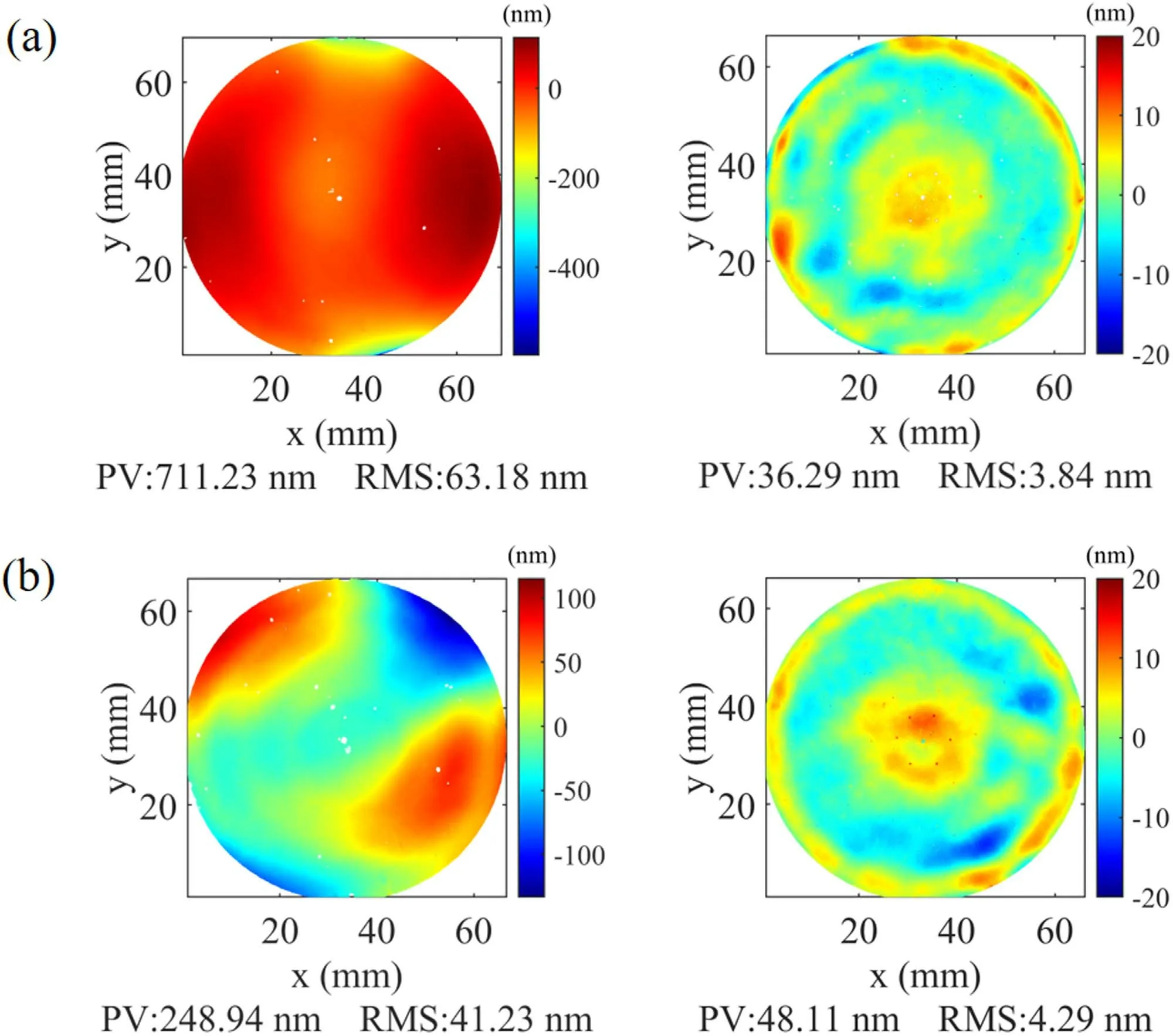
Figure 10.(a) The front and (b) back surface profiles of the compensator before and after IBF.
The null compensator is finished in an iterative process with rotational measurements to obtain a final surface profile.Figure 10 shows the final two surface profiles of the compensator after iterative IBF.The front (Figure 11(a)) and back (Figure 11(b)) initial surface-profile rms values of the compensator are, respectively, 63.18 nm and 41.23 nm, after the figuring of the surface profiles reduces the error to 3.84 nm and 4.29 nm.
4.2.Hyperboloidal Concave Mirror
Before performing null compensation, the initial surface of the hyperboloidal concave mirror should be machined by IBF to meet the requirements of the null test range.IBF results are shown in Figure 11.The surface profile of the closest spherical surface reduces from an initial surface of 326.86 nm rms to 45.57 nm rms.After the surface profile is close to that of a sphere, the aspheric surface measurement, as shown in Figure 3, is conducted by using the null compensator.
The aspherization process can be divided into two stages,as shown in Figure 12.First is a preliminary iterative stage.Here,the main figuring is focused on the aspherical surface deviation errors based on the closest spherical surface.When the surface profile error is figured for a long time, the ion-beam footprint variation due to the heating effect significantly reduces the surface profile accuracy.The surface profile error value of the hyperboloidal concave mirror is about 2 μm PV, and the surface profile slope at the edges exceeds the axis acceleration limitation of the IBF.Thus, the whole etching process can be divided into eight cycles.After the preliminary iterative stage,the surface profile is 41.67 nm rms.The rotation number during the rotation measurement should be confirmed after the rough iterative stage.Second is the precise iteration: After determining the 6-angle rotational measurement to be performed, the precise iterative stage is performed, based on iterative figuring and the results of the 6-angle rotational measurement.After two cycles of iterative figuring, the surface profile finally reaches 8.27 nm rms.As shown in Figure 12, the machined surface remains some mid-frequency errors after several rotational measurements and iterative figuring.The surface roughness is measured by using Bruker AFM,and the measurement range is 5 × 5 μm.The roughness before and after IBF are shown in Figure 13.Many scratches can be observed from the measurement result after CMP takes place as shown in Figure 13(a),and the surface roughness is rms 0.799 nm.After IBF, the surface roughness has significantly diminished to rms 0.160 nm (Figure 13(b)).In previous research (Chkhalo et al.2016), they found that when fused quartz was subjected to ion beam etching under an accelerating voltage ranging from 500 to 1500 eV, and the effective roughness was improved.Furthermore, this improvement in roughness was observed to persist even when the ion beam had a low incidence angle(<30°) of incidence on the sample surface (Figure 13(c)).An increase in etching depth was also found to optimize roughness as shown in Figure 13(d).Our experiments involving relatively maximum angle (<8°) and deep etchings (>1 μm) also satisfied this optimization criterion in the study,because in ion beam processing, we added a 200 nm base etching for each etching cycle to keep the roughness smooth, as shown in Figures 13(e) and (f).

Figure 11.The closest spherical surface figuring of the primary mirror.
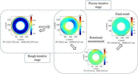
Figure 12.The aspherization process of a hyperboloidal concave mirror.The initial aspherical profile reduces from 502.60 nm rms to 41.67 nm rms in a preliminary iterative stage and the surface profile reduces to 8.27 nm rms by the rotational measurement in a precise iterative stage.

Figure 13.(a)The AFM test result of the hyperboloidal concave mirror before IBF,the roughness is 0.799 nm,and the test is performed at the edge of the mirror;(b)The AFM test result of the hyperboloidal concave mirror after IBF,the roughness is 0.160 nm,and the test is performed at the edge of the mirror;(c)The roughness change with removal depth;(d)The roughness change with angle;(e)When the surface profile error is converted into a removal amount,a base etching was added;(f)The minimum total removal is larger than 1 μm.
5.Conclusion
This paper describes hyperboloidal concave mirror fabrication and measurement of an extreme-ultraviolet telescope.The direct IBF method and the rotational compensation method were both used to improve the surface figure and diminish the roughness.By measuring the single surface figure, the averaging results at different rotation angles were used to evaluate the rotational measurement times.The rotational measurement method can greatly reduce the system errors; it balances efficiency and accuracy before the high-precision stage.The ME and EM methods of rotational measurement were analyzed, and the ME method was found to yield a more accurate calculated machined surface.In our experiment, the spherical surface profile of a null compensator reached to 4 nm rms.Combining rotational measurement and iterative figuring,the hyperboloidal concave mirror surface profile was modified from 326.86 nm rms to 8.27 nm rms.The roughness has also been diminished from 0.799 nm rms to 0.160 nm rms.
Acknowledgments
This work was funded by the National Key R&D Program of China (2022YFF0709101) and the National Natural Science Foundation of China (NSFC) under Nos.62105244 and 61621001.The authors sincerely thank scia Systems GmbH for technical support of the ion source device.
 Research in Astronomy and Astrophysics2023年11期
- Research in Astronomy and Astrophysics的其它文章
- Photometric and Spectroscopic Study of Two Low Mass Ratio Contact Binary Systems: CRTS J225828.7-121122 and CRTSJ030053.5+230139
- Injection Spectra of Different Species of Cosmic Rays from AMS-02, ACECRIS and Voyager-1
- The AIMS Site Survey
- A High-Temperature Superconducting Wideband Bandpass Filter at the L Band for Radio Astronomy
- Modified Masses and Parallaxes of Close Binary Systems: HD 39438
- Detecting HI Galaxies with Deep Neural Networks in the Presence of Radio Frequency Interference
