定位格架对铅铋堆燃料组件热工水力影响的数值研究
张宇扬,陆道纲,王孝天,曹 琼,*,李 臻
定位格架对铅铋堆燃料组件热工水力影响的数值研究
张宇扬1,2,陆道纲1,2,王孝天1,2,曹琼1,2,*,李臻1,2
(1. 非能动核能安全技术北京市重点实验室,北京 102206;2. 华北电力大学核科学与工程学院,北京 102206)
铅铋合金(LBE)作为冷却剂的快堆是第四代核能系统的主要堆型之一。燃料组件的定位格架是燃料棒束的定位结构,同时对燃料组件的热工水力性能也有重要的影响。本研究首先对板翼型格架组件的热工水力特性进行数值模拟,并通过与实验对比,验证了模拟方法的有效性;其次对板翼型、双翼型、单板型三种定位格架组件的热工水力特性进行了数值模拟。结果表明:流经不同格架造成LBE的最高温度位置不同,双翼型、单板型格架组件LBE温度分布更为均匀;格架的翼和板(翼)的中间区域会使对LBE温度均匀起到一定作用的横向速度叠加抵消,单板型格架无此情况;对于格架造成的局部压降,单板型格架阻力系数最小。综合考虑,单板型格架组件的热工水力性能最佳。
铅铋合金(LBE);定位格架;冷却剂通道;热工水力
铅铋堆是第四代核能系统的主要堆型之一,可实现在核动力潜艇、小型电网等供能和供电场所中的应用,具有广阔的发展前景。LBE冷却剂相较于前代反应堆冷却剂的优势较为突出,主要表现在固有安全性高、小型化实现程度高、可持续性好等。
LBE换热实验开展难度较大,表现在冷却剂腐蚀性强,实验温度高,对于实验回路要求高等方面。故CFD方法为研究铅铋堆堆芯热工水力的主要方法之一。目前,研究铅铋堆燃料组件定位结构及其对热工水力的影响主要有:Liu等[1]针对格架定位的铅铋堆燃料组件,研究了适用分析其热工水力的CFD模型,通过湍流普朗特数和湍流模型的配合得到了更精确的数值模拟模型。Yeong等[2]通过实验和模拟相结合的研究方法,提出了适用于液态金属反应堆的一种U形绕丝垫片,用以加强冷却剂的周向混合和降低压降。Pacio等[3]通过实验和模拟对MYRRHA堆绕丝固定燃料组件的热工水力特性进行研究并评估了经验关联式的适用性。Chai等[4]基于RANS方法进行数值模拟,研究了铅冷快堆冷却剂质量流量对缠绕垫片引起的通道间混合的影响。目前研究多是与绕丝定位相关,但对于铅铋堆格架相关的研究较少。由于LBE导热性能优异,对于燃料棒束的定位除了可加强横向搅混的绕丝定位外,在一些小型铅铋堆的应用中,亦可采用格架定位。对于三角布置的燃料棒束,六边形格架是格架的基本形式,但是对于格架外围即贴近组件盒内壁部分的不同设计对热工水力的影响还有待研究。
因此本文基于CFD方法,采用配置三层格架、19棒束的铅铋堆燃料组件模型,分析定位格架的不同结构形式对热工水力性能的影响。
1 计算模型
1.1 几何模型
本文计算所用的几何模型参照于Pacio[5]的格架定位19棒束组件的液态金属冷却剂传热实验,具体参数如表1所示。三层格架布置位置如图1所示。为了便于阐述,令加热段起始位置为0。

图1 格架布置
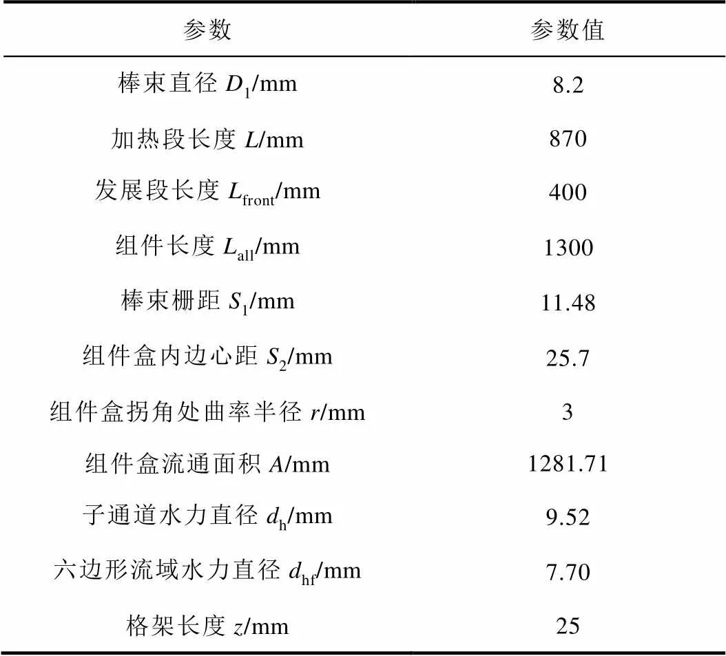
表1 模型参数
1.2 湍流模型
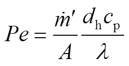
湍流模型可根据数学描述方式不同分为雷诺应力模型和涡粘模型两类,在液态金属流动的数值模拟中,涡粘模型适用性更高。standard-模型与SST-模型更为适用[6]。对于湍流模型中的一项湍流普朗特数Pr的数值,常规流体Pr0.85已经不适用于液态金属。湍流模型一般只建立了湍流黏性,即湍流动量扩散率的模型,并没有直接地定义湍流导热率,即湍流热扩散率模型。为了对湍流导热率建模,定义Pr为湍流动量扩散率与湍流导热率之比。许多学者对Pr的数值进行了研究,本文选取Cheng[7]的经验公式进行计算,并编写UDF(User Defined Function)。Pr的经验公式为:

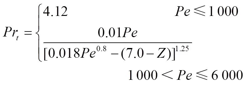
其中:——贝克莱数,表征对流作用与扩散作用的相对大小。
考虑到湍流模型与湍流普朗特数模型的配合使用,standard-模型相对于SST-模型,与Cheng模型配合使用时平均模拟偏差低0.85%[8]。故综合考虑,本文湍流模型选择standard-模型进行数值计算。
1.3 物性参数
为使数值模拟结果更加精确,考虑换热过程中温升对导热率、定压比热、黏度等参数的影响,本文将冷却剂液态LBE的物性参数表示为温度的函数,并编写UDF。LBE物性参数参考文献[9],具体物性参数如表2所示。
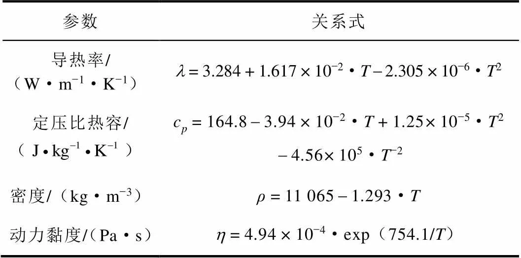
表2 物性参数
2 模型的验证

由于实验工况较多,本文仅选取部分工况进行对比,工况为:体积流量分别为1、2、4、5、6、8、9.23和10 m3/h,入口温度为473.15 K,热功率为50 kW。


图2 模拟值与实验值对比
3 数值计算结果与分析
3.1 模型与网格
本文选取三种格架结构进行对比分析,横截面图如图3所示,模型其他参数如1.1节所述。由于铅铋堆组件盒为六棱柱形式,燃料棒束为三角布置,即中心燃料棒周围有六根燃料棒。故定位格架亦应采用六边布置。三种格架中心子通道均为正六边形,区别在于外围子通道的形状。对于外围格架的常规设计,可考虑两种方式,一是全部采用六边形密排布置,组件盒边缘亦无其他布置;二是仅中心格架采用密排布置,外围简化成单板与组件盒内壁连接的布置。其中图3(a)为实验中所用的格架。其格架外围除了与边缘直接连接的板外,还加了一翼片,为板翼型格架。图3(b)周围子通道也近似为六边形,仅是将连接壁面处的角去掉,为双翼型格架。图3(c)周围子通道为五边形,由内部格架与壁面直接相连构成,为单板型格架。三种格架分别为实验所用格架和常规设计的格架,选取三种格架进行对比,可确定铅铋堆格架设计的基本方案,为进一步设计提供基础。
对几何模型划分的网格是在CFD软件中生成的非结构型多面体网格,为确定合适的网格数量,保证计算精度,根据板翼型格架的模型以网格基础尺寸6 mm、7 mm、8 mm生成了网格数量分别为1 260万、964万、817万的三种网格进行网格无关性分析。
8 mm的网格计算收敛性较差,对于6 mm和7 mm的网格,如图4所示为两个网格的模型沿程温升图,计算结果相差很小,为10-1K数量级,可认为计算结果与网格数量无关。综合考虑网格精度和计算所需时间,最终确定设置网格基础尺寸为7 mm。三种组件的模型均设置为基础尺寸7 mm,网格数量均在950~1000万范围内。并将网格导入FLUENT中进行模拟计算。

图4 网格无关性
3.2 边界条件
对溶解在高温液态LBE中氧浓度的控制,直接影响液态金属水力学性能及其与材料的兼容性。这就要求LBE流速不能过快,需要限制其在一定范围内,本文选取LBE入口体积流量1~5 m3/h。设置燃料棒热功率50 kW、100 kW,LBE入口温度选取473.15 K,入口绝对压力设置为0.25 MPa。外壁面及上下端面设置为绝热。具体工况如表3所示,工况均在<1 500的与实验符合较好的低贝克莱数区域。

表3 工况表
3.3 结果分析
3.3.1不同组件冷却剂温度对比分析
对于LBE的流通区域可划分为42个子通道,按位置不同可分为内部通道、边通道、角通道,如图5所示。其中27、30等为角通道,25、26等为边通道,1、7等为内部通道。

图5 子通道示意图
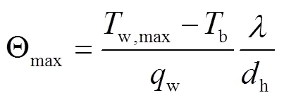
在工况5条件下,三种格架对于LBE温度分布的影响如图6所示,图6为流过第二层格架562 mm处LBE横截面的温度云图。对于边通道,三型组件差异较小,均存在LBE温度较低的情况;对于角通道,板翼型格架组件LBE的最高温度出现在角通道30、36、42处,这三个角通道所在的格架的夹围区域要比角通道27、33、39的小,故出现角通道温度分布不同的现象,其余两型组件无此情况;而对于内部通道,三型组件LBE温度相差不大。对于周向最大温差,板翼型格架组件LBE温差53.0 K,双翼型格架组件LBE温差48.8 K,单板型格架组件LBE温差50.4 K。综合来看,双翼型格架、单板型格架组件LBE温度分布更加均匀。
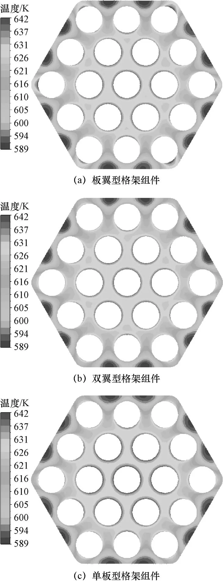
图6 x=562 mm处LBE温度云图


图7 轴向LBE温度分布
对于边通道,流经格架过程中,板翼型格架组件、双翼型格架组件、单板型格架组件温升分别为7.68 K、6.69 K、9.51 K。单板型格架组件LBE后温升幅度更为明显,原因在于其横向速度较大,与附近热流体搅混更为均匀;对于角通道,在格架上游LBE温度就已经受到了影响,流经格架过程温升梯度减小,板翼型格架组件的LBE温度振荡更明显。流经加热段后,由于与周围冷却剂间换热,LBE温度有了一定降低,三型组件温降分别为1.21 K、0.82 K、0.50 K。单板型格架组件LBE温降更小;而对于内部通道,LBE流经格架后,温度产生了小幅振荡,流过加热段温度仍有一定的升高,三种组件内部通道的LBE温度变化趋势较为一致。
3.3.2不同组件冷却剂速度对比分析


图8 x=532 mm处LBE横向速度云图

图9 LBE横向速度分布
3.3.3不同组件冷却剂压降对比分析


随着入口质量流量的增加,LBE压降呈非线性增长,三种格架压降增长率不同。在各个工况下,三种格架造成的压降关系均为:双翼型格架>板翼型格架>单板型格架。Re为37 000时,流经格架造成LBE压降分别为:板翼型格架4 175 Pa,双翼型格架4 387 Pa,单板型格架3 650 Pa。板翼型格架、双翼型格架压降较为接近,单板型格架压降更小。

图11 LBE阻力系数与Re关系
Fig.11 The dragcoefficient-Re relation of LBE
4 结论
本研究采用CFD分析方法,在铅铋堆堆芯燃料组件设计中,对板翼型格架、双翼型格架、单板型格架三种格架结构造成的热工水力影响进行了数值研究。通过数值模拟和分析,得到结论如下:
(1)格架结构对换热影响主要在于:LBE的最高温度位置不同,流经板翼型格架会使个别角通道LBE温度增高,双翼型、单板型格架组件LBE温度分布更为均匀;
(2)格架结构对流动影响主要在于:格架的翼和板(翼)的中间区域会使对LBE温度均匀起到一定作用的横向速度叠加抵消,单板型格架组件无此情况,其LBE的横向速度亦较大;对于格架造成的局部压降,单板型格架阻力系数最小。
综合考虑格架结构对LBE换热和流动的影响,单板型格架在三种格架中综合热工水力性能最佳,可作为铅铋堆格架设计的首选方案,本研究可为铅铋堆的格架设计提供参考。
[1] Liu J,Song P,Zhang D L,et al.Thermal-hydraulic research on rod bundle in the LBE fast reactor with grid spacer[J]. Nuclear Engineering and Technology,2022,54(7):2728-2735.
[2] Yeong S J,Ji Y K,In C B.Enhanced heat transfer and reduced pressure loss with U-pattern of helical wire spacer arrangement for liquid metal cooled-fast reactor fuel assembly[J]. Annals of Nuclear Energy,2020,135.
[3] Pacio J,Wetzel T,Doolaard H,et al.Thermal-hydraulic study of the LBE-cooled fuel assembly in the MYRRHA reactor:Experiments and simulations[J]. Nuclear Engineering and Design,2017,312:327-337.
[4] Chai X,Liu X J,Cheng X.Numerical investigation of thermal-hydraulic behaviors in a LBE-cooled 19-pin wire-wrapped rod bundle[J]. Progress in Nuclear Energy,2020,119.
[5] Pacio J,Daubner M,Fellmoser F,et al.Heavy-liquid metal heat transfer experiment in a 19-rod bundle with grid spacers[J]. Nuclear Engineering and Design,2014,273:33-46.
[6] Thiele R,Anglart H.Numerical modeling of forced- convection heat transfer to lead–bismuth eutectic flowing in vertical annuli[J]. Nuclear Engineering and Design,2013,254:111-119.
[7] Cheng X,Tak N I.Investigation on turbulent heat nuclear applications[J]. Nuclear Engineering and Design,2006,236:385-393.
[8] 王琛,王成龙,张衍,等. 液态铅铋合金管内流动传热特性研究[J]. 原子能科学技术,2021,55(05):822-828.
[9] Fazio C,Sobolev V P,Aerts A,et al.Handbook on Materials Compatibility Thermal-hydraulics and Technologies-2015 Edition[R]. Paris,France:Organization for Economic Cooperation and Development,2015.
Numerical Study on the Effect of Grid Spacer on Thermal-Hydraulics of LBE Fast Reactor Fuel Assembly
ZHANG Yuyang1,2,LU Daogang1,2,WANG Xiaotian1,2,CAO Qiong1,2,*,LI Zhen1,2
(1. Beijing Key Laboratory of Passive Safety Technology for Nuclear Energy,Beijing 102206,China;2. School of Nuclear Science and Engineering,North China Electric Power University,Beijing 102206,China)
As one of the main types of the fourth-generation nuclear power system,the lead-cooled fast reactor has a wide development prospect, which can be applied in the nuclear powered submarine, the small power grid, and other power supply areas. The lead-bismuth eutectic (LBE) is one of the best coolants in the lead-cooled fast reactor. The grid spacer is not only used to support and position the fuel assembly, but also has a certain effect on the thermal-hydraulics of reactor core.However, there are many studies on thermal-hydraulics characteristics of fuel assembly positioned by wire spacer, but there are few relative studies on the grid spacer, and some existing numerical studies lack experimental verification. In order to study the effect of the spacer structure on thermal-hydraulics in the LBE fast reactor core,In a 19-rod fuel assembly with three grid spacers, the flow and heat transfer of coolant LBE in the hexagonal flow channel and spacer-positioned fuel assembly were numerically simulated and analyzed by the CFD method. Firstly, the numerical simulation was carried out for the fuel assembly of the plate-airfoil spacer, and the effectiveness of the simulation method was verified by comparing with the experimental results. Secondly, the thermal-hydraulic characteristics of fuel assemblies with the three grid spacers of the plate-airfoil spacer, the double airfoil spacer and the single plate spacer were compared. The results show that there is some difference in the effect of the three spacers on heat transfer, but great difference on the flow. In particular, the highest temperature of coolant of the plate-airfoil spacer assembly is located in the corner subchannel after flowing through the spacer, and the highest temperature of coolant of the other two assemblies are located near the exit of the internal subchannel. Meanwhile, the coolant temperature of the single plate spacer assembly is higher in all three subchannels. In the middle area of the plate (airfoil) and airfoil of the spacer, the transverse velocity in two directions caused by disturbance will appear superposition cancelling phenomenon. But this is not the case for the single plate spacer, and the transverse velocity of coolant for the single plate spacer assembly is also larger.With the increase of Re, the pressure drop through the three kinds of spacers increases nonlinearly. Of the three types of spacers, the single plate spacer caused the least pressure drop. In a word, the comprehensive thermal-hydraulic characteristics of the single plate spacer assembly is the best among the plate-airfoil spacer, double airfoil spacer and single plate spacer assembly. The single plate spacer can be used as the first choice in the spacer design of lead-cooled fast reactor. The results of this study can provide a reference for the spacer design of lead-cooled fast reactor.
Lead-bismuth eutectic (LBE); Grid spacer; Coolant channel; Thermal-hydraulics
TL333
A
0258-0918(2023)05-1158-09
2022-09-26
张宇扬(1998—),男,辽宁营口人,硕士研究生,现从事反应堆热工水力方面研究
曹琼,E-mail:caoqiong@ncepu.edu.cn

