
The influence of the number of coupling regions on the output of the ding-shaped microring resonator
2023-12-01 05:50:22WURongZHANGHaochen
中国光学 2023年6期
WU Rong,ZHANG Hao-chen
(School of Electronic and Information Engineering, Lanzhou Jiaotong University, Lanzhou 730070, China)
Abstract: In order to explore the influence of the number of coupling regions on the output of the dingshaped microring resonator,the physical model of the ding-shaped microring resonator is established and studied by using the transfer matrix method.On this basis,the influence of the number of different coupling regions on the output of the ding-shaped microring resonator is analyzed.The experimental results show that with the increase of the number of coupling regions,the number of resonance peaks increases in the range of 1.54~1.56 μm working wavelength,the full width at half maximum (FWHM) decreases,the quality factor Q increases,the energy storage performance of the device is better,and the filter function on a specific wavelength can be realized.It can be concluded that the number of coupling regions has a great influence on the performance of the ding-shaped microring resonator.The number of coupling regions is selected according to the actual needs in the design.
Key words: ding-shaped microring resonator;number of coupling regions;transfer matrix;high transmittance
1 Introduction
Since Marcatili A J[1]proposed the concept of microring resonator in 1969,the research on the structure of microring resonator has been carried out for many years[2-6].The structure of the ding-shaped microring resonator was first proposed by Canadian scholar Sacher W D[7]et al.in 2014.Due to the large number of coupling regions of the ding-shaped microring resonator,the transmission loss is large and the increase in the number of coupling regions leads to an increase in the volume of the ding-shaped microring resonator.There are relatively few applications and researches on the ding-shaped microring resonator,mainly focusing on filtering and phase shift.
2 Fundamental theory
The ding-shaped microring resonator is the deformation of the dual-channel microring resonator.The difference is that the dual-channel microring resonator has only two coupling regions,and the standard ding-shaped microring resonator is based on the dual-channel microring resonator.In order to increase the number of coupling regions,the shape of the straight waveguide and the ring waveguide is adjusted,so that four coupling regions are formed,which greatly improves the selectivity of the dingshaped microring resonator to specific wavelengths of light.As shown in Fig.1,C1,C2,C3andC4represent four coupling regions respectively,and CW1and CW2represent two curved waveguides.
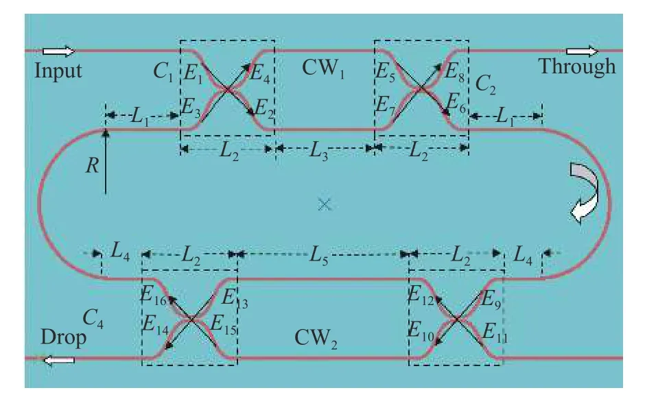
Fig.1 Physical model of standard ding-shaped microring resonator
In this paper,by adjusting the number of coupling regions of the standard ding-shaped microring resonator,the influence of the number of coupling regions on the output spectrum is observed.The physical model of the ding-shaped microring resonator with different numbers of coupling regions is analyzed.The output spectrum and field of the dingshaped microring resonator are analyzed.Since the basic structure of the ding-shaped microring resonator is a directional coupler,the ding-shaped microring resonator model is analyzed by using the transfer matrix[8-10],and the influence of the number of coupling regions on the output of the ding-shaped microring resonator is studied.The coupler structure is shown in Fig.2.
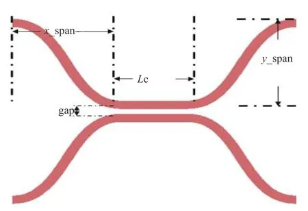
Fig.2 The model of the coupler
By the transfer matrix method,the transfer matrix relationship of the coupling regionC1can be expressed as:
whereE2,E4represent the complex amplitudes generated when the output coupling region isC1;E1,E3represent the complex amplitudes generated when the input coupling region isare the self-coupling coefficients of the coupling regionsC1,andare the cross-coupling coefficients of the coupling regionC1.
As for the uncoupled regionC2,there are:
In the above formulas,E5andE7are the complex amplitudes generated when the input coupling region isC2;φ1,φ2are the phase changes in the phase shifter and they meet φ1+∆φ1=-(φ2+∆φ2).
Similarly,the transfer matrix relationship of the coupling regionC2can be expressed as:
whereE6andE8are the complex amplitudes generated when the output coupling region isC2;t2andare the self-coupling coefficients of the coupling regionsC2;k2andare the cross-coupling coefficients of the coupling regionC2.
In the uncoupled regionC3,the relationship betweenE9andE6can be expressed as:
in the above formula,φL1and φL4are the phase changes on the ring waveguideL1andL4in Fig.1;are representing the transmission coefficients of the ring waveguideL1andL4;E9denotes t he complex amplitude when entering the coupling regionC3;γ=αRexp(jθ/2),where αRis the transmission loss in the semi-ring waveguide;θ is the phase change in a semi-circular waveguide.
Similarly,the transfer matrix relationship of the coupling regionC3can be expressed as:
whereE10andE12are representing the complex a mplitudes generated when the output coupling region isC3;E11is representing the complex amplitude generated when the input coupling region isC3;t3andt3∗are the self-coupling coefficients of the coupling regionsC3;k3andk3∗are the crosscoupling coefficients of the coupling regionC3.
As for the uncoupled regionC4,there are:
in the above formulas,E13andE15are representing the complex amplitudes generated when the intput coupling region isC4;φ3and φ4are the phase changes in the phase shifter and φ3+∆φ3=-(φ4+∆φ4).
Similarly,the transfer matrix relationship of the coupling regionC4can be expressed as:
and there isE3=αL1exp(jφL1)·γ·αL4exp(jφL4)E16.In the above formulas,E14andE16are representing the complex amplitudes generated when the output coupling region isC4;t4andare the self-coupling coefficients of the coupling regionC4;k4,are the cross-coupling coefficients of the coupling regionC4.
After the coupling occurs in the coupling region,the optical signal coupled into the ring waveguide interferes with the optical signal of the ring waveguide.If the two optical signals are in the same direction,they are superimposed during transmission,and the intensity of the optical signal is enhanced when transmitting in the ring waveguide.On the contrary,if the direction of the two optical signals is inconsistent,the two optical signals are canceled during transmission,and the intensity of the optical signal is weakened when transmitting in the ring waveguide.
The Full Width at Half Maximum (FWHM)and quality factor Q are important indicators to measure the performance of microring resonators.The FWHM represents the peak width when the peak height of the output spectral line is half.The smaller the FWHM,the denser the resonance peak at the working wavelength.Since the FWHM is inversely proportional to the quality factor Q,the smaller the FWHM,the larger the quality factor Q,and the stronger the energy storage performance ofthe microring resonator.
From the perspective of energy transfer[11],the optical signal enters the ding-shaped microring resonator from the Input port,and the energy is transmitted along the curved waveguide CW1.After entering the coupling regionC1,the energy is split.A part of the energy is coupled into the ring waveguide and transmitted.The remaining energy will continue to be transmitted along the curved waveguide CW1to the coupling regionC2,and the energy is split again in the coupling regionC2.Most of the energy is coupled into the ring waveguide and transmitted,and the remaining small part of the energy is output from the Through port.When the energy is transmitted to the coupling regionC3,the shunt occurs again.Part of the energy is coupled from the ring waveguide to the curved waveguide CW2and transmitted,and the remaining energy continues to transmit along the ring waveguide.When the energy is transmitted to the coupling regionC4,the shunt occurs again,and most of the energy is coupled to the curved waveguide CW2and output from the Drop port.The coupling region makes the optical signal undergo multiple energy shunts during transmission.The optical signal that does not satisfy the resonance condition will be directly output,and the optical signal that satisfies the resonance condition will continue to be transmitted in the ring waveguide,which increases the selectivity of the microring to the optical signal.
3 The influence of the number of coupling regions on the output spectral lines
WhenL1=10 μm,L2=2 μm,L3=15 μm,L4=5 μm,the coupling distance of the coupling region gap is 0.1 μm,x_span=5 μm,y_span=5 μm,the coupling coefficient is 0.289 6,waveguide thicknessh=0.22,and the working wavelength is 1.54~1.56 μm,the electric field distribution and transmission spectrum[12]of the standard ding-shaped microring resonator are shown in Fig.3(color online).When the optical signal is input from the Input port and passes through the coupling regionC1,the electric field satisfying the resonant condition is coupled into the ring and transmitted along the ring waveguide[13-15].At this time,the Through port has not passed the electric field.According to this mechanism,optical devices with switching function are designed.The remaining electric field continues to transmit along the curved waveguide CW1.When the optical signal is transmitted to the coupling regionC2,the electric field satisfying the resonance condition is coupled into the ring waveguide and transmitted along the ring waveguide,and the remaining electric field is output through the Through port.When the electric field in the ring is transmitted to the coupling regionC3,the electric field satisfying the resonance condition is coupled out of the ring waveguide and transmitted along the curved waveguide CW2,while the remaining electric field continues to transmit along the ring waveguide into the coupling regionC4,and the electric field satisfying the resonance condition continues to transmit along the ring waveguide,while the remaining electric field is coupled to the curved waveguide CW2and output from the Drop port.The resonance condition can be expressed as:
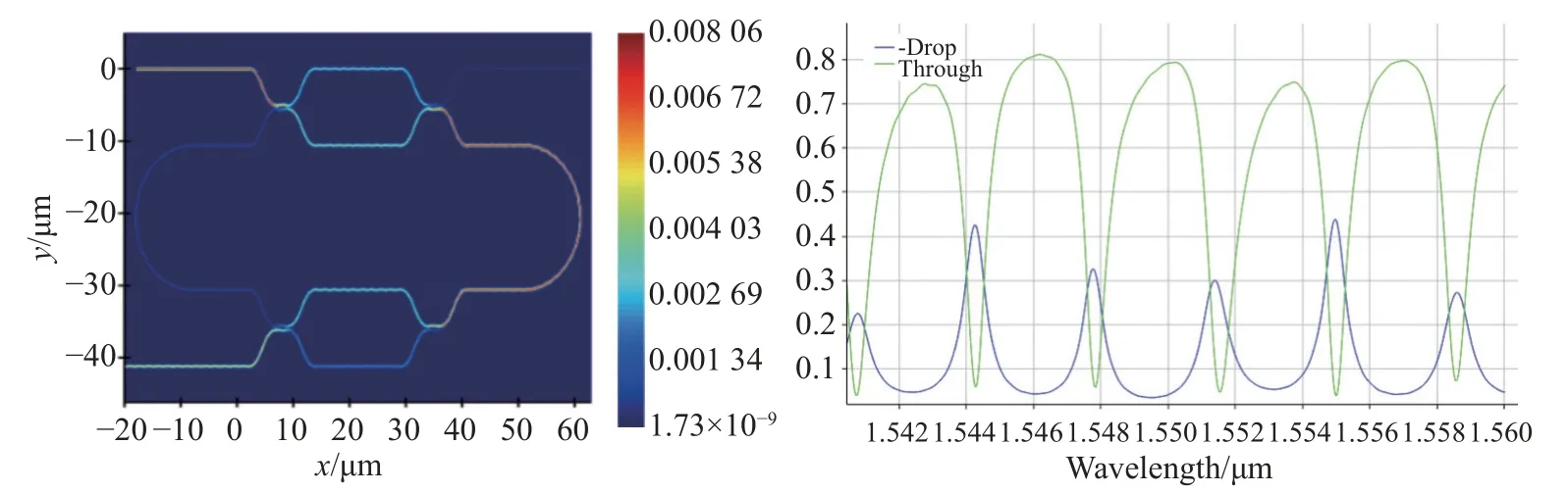
Fig.3 Electric field distribution and transmission spectrum of standard ding-shaped microring resonator
Wheremis the resonant series of the microring resonator,λ0is the wavelength transmitted in vacuum,Lis the circumference of the ring waveguide,andneffis the effective refractive index.In Fig.3,we can see that after the electric field of the input optical signal passes through the coupling regionC1,most of the electric field is coupled into the ring waveguide and transmitted along the ring waveguide.When passing through the coupling regionC2andC3,part of the electric field is transmitted along the ring waveguide,and the other part of the electric field is transmitted to the curved waveguide CW2.When passing through the coupling regionC4,the electric field in the ring waveguide is partially coupled to the curved waveguide CW2and output from the Drop port.The remaining part of the electric field continues to transmit in the ring waveguide until the energy in the ring waveguide tends to be stable,which is consistent with the mechanism of electric field transmission in the micro-ring resonator.From the transmission spectrum of the standard microring resonator,the transmittance of the Through port can reach about 75 %,indicating that the electric field on the curved waveguide CW1can be mostly coupled into the ring waveguide in the coupling regionC2.The transmittance of the Drop port can reach 35 %,indicating that part of the electric field continues to resonate in the ring waveguide,and part of the electric field does not satisfy the resonant condition to couple out of the ring waveguide from the Drop port output.From the overall transmission spectrum,the spectral line is relatively stable and smooth,and has good filtering performance.
Fig.4 (color online) shows the electric field distribution of the microring resonator with different numbers of coupling regions.From Fig.4(a),it can be seen that when the ding-shaped micro-ring resonator has only a pair of coupling zones,the electric field is input from the Input port,most of the electric field is coupled into the ring waveguide,and resonance occurs along the ring waveguide.Only part of the unqualified electric field is output from the Drop port.In Fig.4(b),there are two pairs of coupling zones in the ding-shaped microring resonator.The strength of the electric field entering from the Input port decreases.When the coupling occurs in the four coupling zones,most of the electric field can be continuously coupled in the ring waveguide.Only a small part of the electric field does not meet the coupling condition and is output from the Drop port.In Fig.4(c),there are three pairs of coupling zones in the ding-shaped microring resonator.It can be seen from the diagram that when the electric field enters from the Input port,part of the electric field can be coupled into the ring waveguide and resonate all the time,and a small part of the electric field not meeting the resonance condition output from the Drop port.
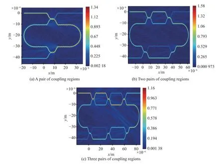
Fig.4 Electric field distributions under different coupling regions
Fig.5 (color online) shows the output spectra when the wavelength range of the input optical signal is 1.54~1.56 μm,and other parameters are unchanged.When the number of coupling regions is one,two and three pairs respectively,the influence of the number of coupling regions on the output spectral line of the ding-shaped microring resonator is simulated.Fig.5(a) shows that when the dingshaped microring resonator has only a pair of coupling regions,four resonance peaks are generated in the working band.The transmittance of the Drop port reaches about 40 %,and the transmittance of the Through port reaches about 85 %.The output spectrum lines of the Drop port and Through port are smooth,and the light waves with the wavelength of 1.542 8,1.544 5,1.553 2 and 1.558 5 μm can be well filtered.It can be seen from Fig.5(b) that when the ding-shaped microring resonator has two pairs of coupling regions,six resonance peaks are generated in the working band.The transmittance of the Drop port reaches about 35 %,and the transmittance of the Through port reaches about 75 %.And the output spectral lines of the Drop port and the Through port are also relatively smooth,which can well filter the light waves with wavelengths of 1.540 2,1.544 5,1.547 8,1.551 4,1.555 0,and 1.558 7 μm.It can be seen from Fig.5(c) that when the ding-shaped microring resonator has three pairs of coupling regions,seven resonance peaks are generated in the working band.The transmittance of the Drop port reaches about 38 %,and the transmittance of the Through port reaches about 70 %.And the output spectral lines of the Drop port and the Through port are also relatively smooth,which can well filter the light waves with wavelengths of 1.541 5,1.544 5,1.547 2,1.549 8,1.552 6,1.555 8,1.558 0 μm.As shown in Fig.5,due to the fluctuation of the light wave during transmission,the refractive index of the material in the light wave of different wavelengths is also different,and the increase of the coupling region affects the occurrence of two adjacent resonances,so the transmittance of the Drop port and the Through port fluctuates within a certain range.
4 Conclusion
In summary,this paper mainly analyzes the physical model of the ding-shaped microring resonator,and simulates the influence of the number of coupling regions of the ding-shaped microring resonator on the output spectrum.It is found that with the increase of the number of coupling regions of the microring resonator,the number of resonance peaks in the working band of 1.54~1.56 μm increases,which means that the density of resonance peaks in the working band increases,and the FWHM decreases.Due to the inverse relationship between the FWHM and quality factor Q,the larger the quality factor Q,the better the energy storage performance of the microring resonator,and the filtering function on specific wavelengths can be realized.

- 中国光学的其它文章
- 惯性传感器地面弱力测量系统热设计
- InGaAs/AlGaAs quantum well intermixing induced by Si impurities under multi-variable conditions
- Orbital-angular-momentum spectra in coherent optical vortex beam arrays with hybrid states of polarization
- A sliding-mode control of a Dual-PMSMs synchronization driving method
- Polarization-multiplexing of a laser based on a bulk Yb:CALGO crystal
- Compact voice coil deformable mirror with high wavefront fitting precision