
Multiple chemical warfare agent simulant decontamination by self-driven microplasma
2023-11-19 13:32ShubinCHEN陈恕彬ShiyuWANG王世宇AnnaZHU朱安娜andRuixueWANG王瑞雪
Plasma Science and Technology 2023年11期
Shubin CHEN(陈恕彬) ,Shiyu WANG(王世宇) ,Anna ZHU(朱安娜) and Ruixue WANG (王瑞雪),*
1 State Key Laboratory of NBC Protection for Civilian,Beijing 102205,People’s Republic of China
2 College of Mechanical and Electrical Engineering,Beijing University of Chemical Technology,Beijing 100029,People’s Republic of China
Abstract Low-temperature plasma is a green and high-efficiency technology for chemical warfare agent(CWA)decontamination.However,traditional plasma devices suffer from the problems of highpower composition and large power-supply size,which limit their practical applications.In this paper,a self-driven microplasma decontamination system,induced by a dielectric-dielectric rotary triboelectric nanogenerator (dd-rTENG),was innovatively proposed for the decontamination of CWA simulants.The microplasma was characterized via electrical measurements,optical emission spectra and ozone concentration detection.With an output voltage of-3460 V,the dd-rTENG can successfully excite microplasma in air.Reactive species,such as OH,O(1D),Hα and O3 were detected.With input average power of 0.116 W,the decontamination rate of 2-chloroethyl ethyl sulfide reached 100% within 3 min of plasma treatment,while the decontamination rates of malathion and dimethyl methylphosphonate reached(65.92±1.65)%and(60.88±1.92)%after 7 min of plasma treatment,respectively.In addition,the decontamination rates gradually decreased with the increase in the simulant concentrations.Typical products were identified and analyzed.This study demonstrates the broad spectrum and feasibility of the dd-rTENG-microplasma for CWA elimination,which provides significant guidance for their practical applications in the future.
Keywords: triboelectric nanogenerator,microplasma,decontamination,chemical warfare agents,simulants
1.Introduction
Chemical warfare agents (CWAs) are usually highly toxic chemicals that can cause mass casualties,which were first used during World War I where they caused huge casualties[1].With the signing and entry into force of the Chemical Weapons Convention,the possibility of CWAs being used in large-scale military operations has been reduced,but the possibility of being used by terrorists to carry out terrorist attacks or illegal military action cannot be ruled out.Therefore,the emergency decontamination technology of CWAs has always been an important part of the public safety technology system [2].Traditional CWA decontamination technologies,such as high-temperature incineration [3,4],hydrolysis [5,6] and chemical decontaminants [7,8],suffer from the problems of poor decontamination efficiency,complex operation procedures and serious environmental pollution.Therefore,it is necessary to explore a safe,efficient and green technology for CWA decontamination.
In recent years,low-temperature plasma technology has attracted considerable attention for CWA elimination.The highly reactive species in plasma,such as electrons,OH,O(1D),ONOO-and O3,have demonstrated excellent decontamination performance for a wide range of CWAs[9].In 1999,Herrmann et al [10] used a plasma jet for the decontamination of mustard gas and VX simulants,and verified their excellent decontamination performance.In 2002,Moeller et al [11] used a plasma flare device to degrade the Salin simulant dimethyl methylphosphonate(DMMP).Here,5 μl DMMP was almost completely eliminated after 10 min of plasma treatment.Subsequently,researchers have conducted extensive research on plasma decontamination technology.Chen et al [12] used a pulsed power supply to excite a dielectric barrier electrode to decontaminate the mustard gas simulant 2-chloroethyl ethyl sulfide (2-CEES).At a discharge power of 45.2 W,the degradation rate of 180 ppm 2-CEES reached 93%after 20 min of plasma treatment.Yi et al [13] investigated the decontamination effect of a plasma jet induced by a pulsed power source on the VX simulant malathion.After 20 min of treatment,the degradation rate of 1.2 mg malathion reached 100%at an input power of 22.5 W.Yehia et al[14]investigated the decontamination effects of plasma on DMMP.The results showed that the degradation rate of 20 mg l-1DMMP (50 ml) reached 85.55% after 20 min of treatment at a discharge power of 100 W.The abovementioned studies demonstrated that plasma showed excellent decontamination effects on various CWAs or simulants.However,the high power consumption and large size of the excitation power supply limited its practical applications.
Unlike conventional excitation power sources,triboelectric nanogenerators (TENGs) have the advantages of flexible structural design,low cost and small size and are selfdriven.By converting mechanical energy into electrical energy,a TENG can easily generate a high voltage of several kilovolts and precisely control the amount of electron emission [15-17].Currently,TENG-excited plasmas are used in many applications,such as field emission [18,19],mass spectrometry sources[20,21],material synthesis[16,22]and environmental protection [23,24].For example,Han et al[25] used polytetrafluoroethylene (PTFE) film and a quartz glass tube to generate UV plasma radiation in Ar-Hg lowpressure gas.Li et al[26]proposed a novel and efficient CO2catalytic conversion system using TENG-driven plasma to activate CO2conversion.Cheng et al [27] successfully demonstrated four typical microplasmas induced by TENG,including dielectric barrier discharge (DBD),plasma jets,corona discharge and micro-discharge.
In this work,a dielectric-dielectric rotary TENG (ddrTENG)microplasma decontamination system is proposed to eliminate a variety of CWAs.At 600 r min-1,the dd-rTENG achieved a maximum output voltage of 4 kV.Here,2-CEES,malathion and DMMP were selected as simulants of mustard gas,VX and sarin,respectively.Optical and electrical characterization techniques were used to study the discharge performances.The decontamination products were evaluated using gas chromatography (GC).
2.Experiment
2.1.Fabrication of dd-rTENG microplasma decontamination system
The dd-rTENG microplasma decontamination system was mainly composed of four parts: the dd-rTENG,a rectifier,a needle-plate electrode and a decontamination chamber,as shown in figure 1.The dd-rTENG consisted of three parts:the stator,the rotor and the spacer.An acrylic disc with a diameter of 30 cm and a thickness of 3 mm was used as the base for the stator and rotor.A sensing electrode-aluminum foil-was attached to the surface of the acrylic plate of the stator.The aluminum foil was divided into 12 sectors and the interphase sectors were conductive to each other.The adjacent sector electrodes were spaced 3 mm apart,which resulted in two aluminum foil induction electrodes.Each of them contained six fan-shaped electrodes.The rotor was driven by a rotary motor.PTFE was pasted on the surface of the rotor as an independent layer.It was cut into six sectors of the same size as the scalloped aluminum electrodes and distributed evenly over the surface of the disc.The paper was placed between the stator and rotor as a spacer layer,and a source of charge replenishment.The stator was in constant contact with the paper during rotation.
A tungsten needle electrode with a tip radius of 0.22 mm and length of 180 mm was used for plasma generation.The simulants were placed in an aluminum crucible (diameter of 6.7 mm,height of 6 mm,thickness of 0.2 mm) for plasma treatment.The distance between the tungsten needle electrode and aluminum crucible was fixed at 1 mm.All the parts of the discharge device were placed in a closed glass container for safety.The rectifier consisted of four voltage-resistant diodes(R5000,DO-1) that converted the AC power output to DC power.The negative voltage was connected between the tungsten needle electrode and aluminum crucible.
2.2.Working principle of dd-rTENG
Based on the principle of the coupling effect of friction electrification and electrostatic induction [28],the working principle of the dd-rTENG is shown in figure 2.PTFE and paper were used as friction materials.PTFE was more likely to gain electrons and paper was more likely to lose electrons in the frictional electrical sequence [29].When PTFE and paper rubbed against each other,PTFE carried positive charges and the paper carried negative charges.Before this,PTFE had already carried a small number of negative charges and,after sufficient friction with the paper,more negative charges were generated on its surface (frictional charging).Firstly,the paper served as a source of charge replenishment to reduce charge dissipation.Secondly,as a spacer layer,the paper separated the rotating PTFE from the stationary aluminum electrode,avoiding damage or wear to the aluminum electrode and extending the device life.The dd-rTENG can work normally for more than one month when the relative humidity of the environment is between 20% and 40%.
Further,the negative charges on the PTFE (1) surface induced an equal number of positive charges (electrostatic induction) on the bottom aluminum electrode in addition to the positive charge of the corresponding paper(I).In the schematic in figure 2,aluminum electrodes(1)and(2)were connected by a load.Due to the unique distribution form of the bottom aluminum electrode and electrostatic induction,when PTFE (1) passed through aluminum electrodes (1) and (2),electrons flowed between them and a rightward current (II) flowed in the load.PTFE(1)continued to move,carrying negative charges past the top of the aluminum electrode (2) (III).Finally,PTFE (1) gradually left the aluminum electrode (2),PTFE (2) entered the aluminum electrode (1),and a leftward current (IV) flowed in the load.After the above four steps,the dd-rTENG completed one cycle of AC output.
2.3.Discharge characterization
Voltage and current measurements were measured using high-voltage probes (Tektronix,P6015A,1000:1),a variable resistor box and an oscilloscope (Tektronix,DPO2024B,200 MHz).Since the discharge current was at the micro-amp level,it was measured indirectly by recording the voltage across the resistor.The optical emission was measured using an emission spectrometer (FX2000+RD,Fuxiang,China),and the emission spectrometer was calibrated by a standard Hg light source.The optical fiber was placed close to the discharge chamber,and the optical emission was recorded with an integration time of 100 ms.A pump ozone (O3)detector (XLA-BX-O3,Pulitong,China) was used for O3detection,which was calibrated via a UV-method-based O3detector.After a certain discharge time in the closed chamber,the suction port of the detector was placed in the chamber and the highest ozone concentration value was recorded.
2.4.CWA simulant decontamination and product detection
Prior to decontamination,the aluminum crucible was cleaned using 40 μl acetonitrile.Subsequently,40 μl CWA simulants(50 mg l-1,100 mg l-1,150 mg l-1) was placed in the aluminum crucible,and the solvent was acetonitrile.After plasma treatment for a certain time,the residual liquid was removed and fixed to 200 μl via dichloromethane dilution.After sufficient shaking with a vortex oscillator,the samples were detected using GC(Thermo Scientific Trace 1300).Humidity affects the output performance of the dd-rTENG and the contents of plasmagenerated active species;therefore,the relative humidity of the environment during the experiments was monitored by a thermohygrometer and controlled at 20%-30% to minimize errors.Each experiment was repeated three times to obtain error bands.The GC column was DB-5MS (5% phenyl-methyl polysiloxane),30 m × 0.25 mm × 0.25 μm (Palo Alto,CA,USA).The GC parameters were set as follows: a spitless injection model;injection temperature of 220°C;injection time of 1 min;gas sample injection volume of 100 μl;liquid sample injection volume of 1 μl;carrier gas(N2),flow rate of 1.0 ml min-1.The GC temperature control procedure was set as follows: maintaining temperature at 50°C for 1 min,increasing temperature to 280°C at a rate of 10°C min-1and then maintaining for 5 min.
3.Results and discussion
3.1.Electrical characterization of dd-rTENG microplasma
Figure 3 shows the circuit diagram and measurement results for the output electrical characteristics of the dd-rTENG.As shown in figures 3(a)and(b),a 4 MΩ load resistor was used for the current measurement.At 600 r min-1,the unrectified dd-rTENG output voltage,current and frequency reached 4160 V,160 μA and 54 Hz,respectively (figure 3(c)) and the average power was 0.309 W.The average power was calculated by integration between the voltage and current and divided by the discharge period.After rectification,the state of the dd-rTENG changed to bias voltage.The output voltage,current and frequency were -3460 V,-138 μA and 108 Hz,respectively (figure 3(d)),and the average power was calculated as 0.285 W.The voltage and current after rectification were decreased due to the fact that the rectifier has a certain internal resistance that consumes part of the power output of the dd-rTENG.Nevertheless,this output performance was sufficient to induce plasma.

Figure 3.Electrical characteristics of the dd-rTENG.(a)The measurement circuit diagram without rectification,(b)the measurement circuit diagram with rectification,(c) voltage and current curves without rectification and (d) voltage and current curves after rectification.
The needle-plate electrode(tungsten needle electrode and aluminum crucible with 1 mm electrode spacing)was adopted as a plasma generator and was placed in a closed chamber as the decontamination electrode.As shown in figure 4(a)(i),the high-voltage output of dd-rTENG can successfully induce plasma,and the plasma coverage had a diameter of 1.34 mm when the plasma treated the simulant liquid.Figures 4(a) (ii)and (iii) show the two discharge models,including arc discharge and corona discharge,respectively.When there was no medium,the plasma was a bright-white arc discharge.After the addition of acetonitrile,the plasma changed to a lavender corona discharge.
Further,the voltage and current of the microplasma were measured (figure 4).The measurement circuit is shown in figure 4(b).Previous studies have shown that the negative DC mode had better discharge and decontamination effects [30];therefore,negative DC was used as the discharge mode in this study.In the arc discharge state,the discharge voltage and current were -2240 V and -340 μA,respectively(figure 4(c)),and the average power was calculated as 0.117 W.In the corona discharge state,the discharge voltage and current were -1680 V and -230 μA,respectively(figure 4(d)),and the average power was calculated as 0.116 W.The average discharge powers of the arc discharge and corona discharge were calculated as 0.117 W and 0.116 W,respectively,via the variation of electrical energy with time for one discharge cycle (figures 4(e) and (f)).The electrical characteristics data may fluctuate somewhat with ambient temperature and humidity and the degree of wear and tear of the device.The dd-rTENG power utilization was calculated as only 51% due to the internal resistance of the dd-rTENG.In addition,the voltage and current values of the corona discharge were lower than those of the arc discharge,but the discharge power values were similar.This was due to the fact that acetonitrile had a certain conductivity (dielectric constant 35),and the addition of acetonitrile or simulant was equivalent to shortening the distance between the needle and plate,resulting in reduced internal resistance,a lower discharge voltage and higher discharge frequency.However,since the amount of charge transferred per cycle was constant[30],the frequency increased while the peak current decreased.
3.2.Emission spectra and ozone concentration
Air plasma contains a variety of reactive species and highenergy electrons that are essential for CWA decontamination.Figure 5(a) shows the emission spectra of the corona discharge with acetonitrile as the medium.The results showed that reactive species,such as OH (A2∑+→X2∏) at 306-309 nm,N2second positive system N2(C3∏u→B3∏g) at 330-420 nm,first negative systemat 390-420 nm,Hαat 656.3 nm and O at 777 nm,were observed [31-33].In addition,due to the presence of acetonitrile,C-H (C2∑+→X2∏) and C-H (A2Δ→X2∏)emissions were observed at 315.9 nm and 432.9 nm,respectively,and CII emission was observed at 426.7 nm.Furthermore,the spectra of the plasma were acquired when 2-CEES,malathion and DMMP were used as the medium (figure S1).However,no significant differences were observed,probably due to the low emission intensity.
The main relevant reactions for the generation of active species are as follows [34-36]:
Reactions (1)-(3) are the main generation reactions of O-related reactive species.Among them,O(1D)further reacts with H2O to form OH.Reactions (4) and (5) are the main formation reactions of OH.OH and reactive oxygen species are important oxidizing species in plasma.In particular,OH has the best oxidation performance with an oxidation potential of 2.8 eV and O(1D) with an oxidation potential of 2.2 eV,which can oxidize and decompose a variety of CWAs [2,12].
Besides the above short-lived species (duration 10-8s),ozone,as a long-life species (duration 10-3s),also presents excellent oxidation performance[37].The oxidation potential of ozone was 2.07 eV.Figure 5(b) shows the ozone concentration in negative DC mode during the time of 0-320 s.The results showed that the ozone concentration presented a good linear relationship with the plasma treatment time.The ozone concentration reached 21.43 mg m-3after 320 s of plasma discharge.The main reactions for ozone generation are listed as follows:
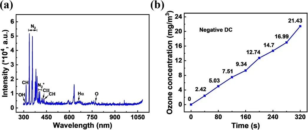
Figure 5.The emission spectra and ozone concentration.(a)Emission spectra of corona discharge with acetonitrile,(b)the variation curve of ozone concentration in negative DC mode.

Figure 6.Decontamination of 2-CEES.(a)A chromatogram of 100 mg l-1 2-CEES with different treatment times;(b)the peak area change curve of 100 mg l-1 2-CEES;and (c) decontamination rates of different concentrations of 2-CEES at 2 min (*: 0.01<p<0.05;**:0.001<p<0.01;***: p<0.001).
3.3.Decontamination of CWAs simulants
In this study,the dd-rTENG microplasma decontamination system was used to decontaminate 2-CEES,malathion and DMMP.GC was used for qualitative and quantitative analysis of the decontamination performance.The content of the substance was characterized by the area or height of the peak in the chromatogram,and the decontamination rate was calculated using the equation:
where D is the decontamination rate of the simulant,P0is the area of the peak of the simulant without treatment and Ptis the area of the peak of the simulant after t min of treatment.The decontamination products and decontamination rates of different CWA simulants were studied.
3.3.1.2-CEES decontamination.To investigate the effect of microplasma treatment time on 2-CEES decontamination,40 μl 100 mg l-12-CEES was exposed to plasma with treatment time of 1-7 min (with time intervals of 1 min).As shown in figure 6(a),the retention time of the 2-CEES spectra appeared at 6.87 min.The peak value gradually became smaller with the increase in the treatment time,and disappeared completely at 2 min.The peak area of initial 2-CEES was 1.144 ± 0.214,and the peak area decreased to 0.046 ± 0.066 after 2 min of treatment,corresponding to a decontamination rate of(95.95±5.73)%.After plasma treatment of 3 min,the characteristic peak disappeared,indicating complete removal of 2-CEES (figure 6(b)).To investigate the effect of 2-CEES concentration on the decontamination rate,2-CEES with different initial concentrations was used.The results showed that the decontamination rates of 50 mg l-1,100 mg l-1and 150 mg l-12-CEES were(99.68±0.05)%,(95.95±5.73)% and(85.61±2.83)% at 2 min,respectively (figure 6(c)).The degradation rate gradually decreased with the increasing 2-CEES concentration.Significant difference analysis was performed on the decontamination rates,and there was a significant difference between 50 mg l-1and 150 mg l-12-CEES,with a P-value of 0.0136.

Figure 7.Decontamination products of 2-CEES.(a)Chromatograms of 2-CEESO and 2-CEESO2 with different treatment times,(b)the peak area change curve of 2-CEESO and (c) the peak area change curve of 2-CEESO2.
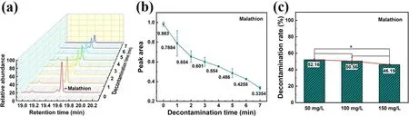
Figure 8. Decontamination of malathion.(a) A chromatogram of 100 mg l-1 malathion with different treatment times,(b) the peak area change curve of 100 mg l-1 malathion and(c)decontamination rates of different concentrations of malathion at 5 min(*:0.01<p<0.05;**:0.001<p<0.01;***: p<0.001).
Oxidation is the main pathway for 2-CEES decontamination [38].The oxidation products 2-chloroethyl ethyl sulfoxide (2-CEESO) and 2-chloroethyl ethyl sulfone(2-CEESO2) were observed.The chromatograms of 2-CEESO and 2-CEESO2appeared at 11.12 min and 11.43 min (figure 7(a)),respectively.The content of 2-CEESO reached the highest level at 2 min,while 2-CEES was almost completely decontaminated,and then gradually decreased(figure 7(b)).In contrast,the content of 2-CEESO2was consistently increased(figure 7(c)).The results indicated that the decontamination process of 2-CEES was a step-bystep oxidation process.The 2-CEES was first oxidized to 2-CEESO by the active species,and then 2-CEESO was further oxidized to 2-CEESO2.
3.3.2.Malathion decontamination.The chromatograms and peak areas of 40 μl 100 mg l-1malathion after 1-7 min microplasma treatment are shown in figure 8.The retention time of malathion was 19.61 min.The characteristic peaks gradually decreased with increasing treatment time.It should be noted that the liquid disappeared completely after 7 min of plasma treatment.However,after elution of the container with acetonitrile,a certain amount of malathion was still detected.This is due to the fact that the solvent acetonitrile is more volatile than the simulant,and the area of the simulant that can be treated was reduced after the solvent was completely evaporated.The degradation rate was slower than the volatilization rate of acetonitrile.Meanwhile,the plasma state changed from a corona discharge to an arc discharge;thus,the plasma coverage diameter was reduced from 1.34 mm to 0.5 mm.The treatment area not only became smaller,but the active species was not able to spread through the liquid.Therefore,malathion cannot be completely decontaminated.The peak area of malathion without plasma treatment was 0.983±0.023.After 7 min of plasma treatment,the peak area changed to 0.335±0.017,corresponding to a decontamination rate of (65.92±1.65)%.Similarly,the decontamination rate of malathion also decreased with the malathion concentration.The decontamination rates of 40 μl 50 mg l-1,100 mg l-1and 150 mg l-1malathion were (52.16±1.26)%,(50.56±4.6)% and (46.19±0.64)% at 5 min (figure 8(c)),respectively.A significant difference between 50 mg l-1and 150 mg l-1malathion was observed,with a P-value of 0.0164.

Figure 9. Decontamination products of malathion.(a) Chromatograms of malaoxon with different treatment times,and (b) the peak area change curve of malaoxon.

Figure 10.Decontamination of DMMP.(a)A chromatogram of 100 mg l-1 DMMP with different treatment times,(b)the peak area change curve of 100 mg l-1 DMMP and (c) decontamination rates of different concentrations of DMMP at 5 min (*: 0.01<p<0.05;**:0.001<p<0.01;***: p<0.001).
The decontamination process of malathion was accompanied by oxidation and the breaking of chemical bonds.The chromatograms of malaoxon were observed at the retention time of 19.51 min after plasma treatment at different times,as shown in figure 9(a).Two other peaks on its right side were presented in both control and experimental samples,indicating that they were impurity peaks.The concentration of malaoxon increased and then decreased with increasing treatment time(figure 9(b)).The highest concentration was reached at 4 min,with a peak area of 0.043 ± 0.005.At 6 min,the malaoxon content was reduced by about 30%.These results were consistent with those reported in the relevant literature [13].
3.3.3.DMMP decontamination.Figures 10(a) and (b) show the decontamination results of 40 μl 100 mg l-1DMMP.The characteristic peak of DMMP appeared at 6.12 min(figure 10(a)).After plasma treatment for 1-7 min,the peak gradually decreased.There was no residual liquid remaining in the container after 7 min of plasma treatment.However,DMMP was still detectable after acetonitrile elution.The residual DMMP might come from the container wall,where plasma cannot reach.The peak area curves of DMMP for different treatment times are shown in figure 10(b).The peak area of DMMP without treatment was 1.322 ± 0.087,and changed to 0.517 ± 0.025 after 7 min of plasma treatment,corresponding to a decontamination rate of(60.88±1.92)%.Furthermore,40 μl 50 mg l-1,100 mg l-1and 150 mg l-1DMMP were decontaminated,and the decontamination rates were (51.93 ± 1.75)%,(45.61 ± 2.06)% and (44.66 ±2.04)%at 5 min,respectively(figure 10(c)).The results of the significant difference analysis showed highly significant differences in the decontamination rates of the three concentrations (P-value: 0.0004 for 50 mg l-1and 100 mg l-1,0.00008 for 100 mg l-1and 150 mg l-1,and 0.00027 for 50 mg l-1and 150 mg l-1).

Figure 11.Decontamination products of DMMP.(a)Chromatograms of DMMP products with different treatment times,and(b)the peak area change curve of DMMP products.
Figure 11(a) shows the chromatograms of DMMP decontamination products at different treatment times.The characteristic peaks of formic acid (FA),methylphosphonic acid (MA) and methylphosphonate methyl carbinol ester(MPMCE) with retention times of 4.35 min,4.9 min and 6.9 min,respectively,were detected.The products and the retention time are consistent with those previously reported[39].Figure 11(b) shows the variation of the three products together with the increase in plasma treatment time.The contents of FA and MA increased and then decreased with increasing treatment time,and reached the highest level at 5 min.The content of MPMCE was the lowest,but its production continued to increase.
Figure 12 compares the decontamination effects of the three CWA simulants.The decontamination efficiency of 2-CEES was the highest compared with malathion and DMMP (figure 12(a)).The decontamination of 2-CEES was mainly through the oxidation of the S atom,while malathion and DMMP were more difficult to decontaminate due to the stability of P=S bonds and P=O bonds,respectively.Figure 12(b) compares the decontamination rates of the three simulants at 7 min.The decontamination rates of malathion and DMMP were (65.92±1.65)% and (60.88±1.92)%,respectively.A highly significant difference in the decontamination rate between malathion and DMMP was observed(P-value:0.0005).This is due to the fact that the bond energy of P=S in malathion (335 kJ mol-1) is lower than that of the P=O bond in DMMP (544 kJ mol-1) [14].Under the same conditions,the energy required to decontaminate DMMP molecules is higher than that of malathion.
Finally,the energy utilization efficiency (Ee) of the decontamination system was calculated and compared with the relevant reports according to the following formula.
where ΔC is the content of the decontaminated simulant,P is the discharge power and t is the treatment time.The Eeof the decontamination system was 0.28 μg J-1,0.054 μg J-1and 0.05 μg J-1for 2-CEES,malathion and DMMP,respectively.The Eeof 2-CEES was one order of magnitude higher thanthat reported in the related reports,and malathion and DMMP reached the same level as in the related reports (table 1).
4.Conclusion
In this paper,the decontamination performance of a ddrTENG microplasma decontamination system for a variety of CWA simulants was studied.With an output voltage of-3460 V,the dd-rTENG can successfully excite microplasma in air.The microplasma can generate reactive species,such as OH,O(1D),Hαand O3,in the air environment.The decontamination rate of 2-CEES reached 100%within 3 min,while malathion and DMMP reached (65.92±1.65)% and (60.88±1.92)% at 7 min,respectively.Malathion and DMMP were more difficult to eliminate compared with 2-CEES due to the stability of P=S bonds and P=O bonds.With regard to the decontamination products,typical products were identified and analyzed.Oxidation and chemical bond breakage are still the main ways to eliminate simulants.This study not only demonstrates the broad spectrum and high efficiency of the dd-rTENG microplasma for CWA simulants decontamination,but also has important implications for further optimization of the decontamination process of CWAs.In future work,the differences in the generation of active species by TENG-excited plasma and conventional plasma can be explored,and the mechanism of CWA decontamination by TENG microplasma can be refined.
Acknowledgments
This work was supported by National Natural Science Foundation of China(No.51877205),Fundamental Research Funds for the Central Universities(No.buct201906),the State Key Laboratory of NBC Protection for Civilian (No.SKLNBC2021-0X) and Beijing Nova Program (No.2022015).
猜你喜欢
大众文艺(2022年21期)2022-11-16
美与时代·美术学刊(2021年10期)2021-11-25
中老年保健(2021年12期)2021-08-24
金桥(2021年2期)2021-03-19
音乐天地(音乐创作版)(2020年7期)2020-09-11
小学生(看图说画)(2020年4期)2020-04-01
小学生(看图说画)(2020年4期)2020-04-01
青年生活(2020年5期)2020-03-27
中国农资(2019年2期)2019-01-15
小主人报(2015年3期)2015-02-28
 Plasma Science and Technology2023年11期
- Plasma Science and Technology的其它文章
- Preparation of highly efficient antibacterial non-woven by facile plasma-induced graft polymerizing of DADMAC
- Wet flashover voltage improvement of the ceramics with dielectric barrier discharge
- Experimental and numerical investigation on the uniformity of nanosecond pulsed dielectric barrier discharge influenced by pulse parameters
- Investigation of phase modulation and propagation-route effect from unmatched large-scale structures for Doppler reflectometry measurement through 2D full-wave modeling
- SOLPS-ITER drift modeling of neon impurity seeded plasmas in EAST with favorable and unfavorable toroidal magnetic field direction
- Preparation of a beam emission spectroscopy diagnostic based on a Lymanalpha line to diagnose core and edge-plasma density fluctuation on the HL-2A tokamak