Development of a doppler asymmetric spatial heterodyne interferometer for ground-based wind field detection at the 557.7 nm wavelength
LIU Huan,JIANG Lun,2,3*,ZHANG Xiao-fei,FU Yun,SONG Yan-song,2,3,TONG Shou-feng,2,3,LIU Xian-zhu,2,3
(1.School of Opto-Electronic Engineering, Changchun University of Science and Technology,Changchun 130022, China;2.Peng Cheng Laboratory, Shenzhen 518000, China;3.Key Laboratory of Fundamental Science for National Defense of Aero and Ground Laser Communication Technology, Changchun University of Science and Technology, Changchun 130022, China)
* Corresponding author,E-mail: jlciomp@163.com
Abstract: A ground-based Doppler Asymmetric Spatial Heterodyne (DASH) interferometer with a high Signal-to-Noise Ratio (SNR) and large etendue (AΩ) with thermal compensation was developed to detect wind field information in the middle atmosphere.The detailed parameters and index of the DASH interferometer were developed for the 557.7 nm oxygen airglow spectral line.The system was designed with an expanded Field Of View (FOV) and thermal compensation.The half-FOV angle reached 2.815°, the etendue was 0.095 25 cm2sr, and the system’s SNR was approximately 113.75.Through the thermal compensation design,the final optical path difference with temperature variation (dΔd0/dT) was only 2.224×10⁻⁷mm/°C.The optical system was designed and optimized according to the corresponding parameters.Image-side telecentric and bilateral telecentric optical system structures were used in the entrance optics and exit optics, respectively,and parameters such as telecentricity and distortion met the detection requirements.To verify the design results, a ground-based DASH interferometer experimental platform was constructed, and indoor and outdoor ground-based experiments were conducted.In the final experiment, clear interference fringes were obtained,which proves that the system design results of the DASH interferometer are reasonable, and the system’s SNR and etendue meet the detection requirements.
Key words: ground-based DASH interferometer; 557.7 nm oxygen atom airglow spectral line; optical design; signal-to-noise ratio
1 Introduction
The wind field in the middle and upper atmosphere affects climate change, the flight trajectory parameters of spacecraft, and the precise guidance of military missiles.Therefore, it is necessary to research the accurate and efficient detection of windfield information.Over the last century, the Fabry-Perot interferometer has been regarded as a typical passive wind-measuring device owing to its high sensitivity and small temperature influence on the optical path difference of the interferometer.However, the Fabry-Perot étalon has high accuracy requirements and a difficult manufacturing process.Additionally, its Field Of View (FOV) is not easily broadened (usually less than 2°)[1], resulting in a low Signal-to-Noise Ratio (SNR).The Michelson interferometer is another device commonly used for passive wind measurements and it tracks the Doppler frequency shift by monitoring the phase shift of multiple interference fringes.FOV broadening technology can be used to expand the FOV.However,dynamic measurement methods reduce the measurement accuracy of the wind speed[2].
Doppler Asymmetric Spatial Heterodyne (DASH) technology has both grating diffraction and spatial interference capabilities.In the optical path, an FOV prism can be used to increase the FOV of the system to obtain a large etendue and SNR.Moreover, DASH technology has a series of advantages,such as high spectral resolution and simultaneous multi-spectral line static detection.Since 2006,DASH has been used to detect middle and upper atmospheric wind fields[3].The DASH interferometer takes the airglow spectral line in the middle and upper atmosphere as the light source, inverts the windfield parameters via the Doppler effect of the spectral line, and finally obtains the wind speed using the interference absolute phase difference.Owing to its high resolution and simple structure, the DASH system has clear advantages in detecting atmospheric spectral Doppler shifts, which has attracted the attention of many research teams.
Englert[3]proposed the concept of DASH technology to detect the wind field in the middle and upper atmosphere in 2006.They used a breadboard to detect two lasers that simultaneously changed the voltage and found that they caused the same trend in interference phase changes.The feasibility of DASH technology for multispectral line observation and real-time phase tracking was subsequently verified[3].The following year, with the support of the US Naval Laboratory, the first breadboard structure of a DASH interferometer without an expanded FOV was constructed[4].In 2010, a ground-based (Redline DASH Demonstration, REDDI)[5]and airborne(Redline Interferometer for Doppler Winds, ARROW)[6]principle prototype was successfully developed for the oxygen red line with a wavelength of 630 nm in the atmosphere, and a spectral line with a wavelength of 630.48 nm emitted by an Ne lamp was used for calibration and real-time phase calibration.Launched on the Ionospheric Connection Explorer (ICON) satellite in October 2019, the Michelson Interferometer for Global High-resolution Thermospheric Imaging (MIGHTI) developed by the team can remotely measure atmospheric wind and temperature fields within a range of 90-300 km from Earth by detecting the naturally occurring red(630.0 nm) and green (557.7 nm) lines of oxygen atoms and oxygen molecules (762 nm) near airglow spectral lines[7-8].
By building the DASH interferometer platform,New York University conducted a wind-field simulation experiment with a 630 nm Ne laser and obtained wind speed data by preliminary inversion[9].Using this, the SWIFT-DASH principle prototype for stratospheric wind-field and infrared ozone detection was developed, which opened a new avenue for expanding infrared ozone detection[10].
The Anhui Institute of Optics and Fine Mechanics developed a large-offset DASH interferometer (LODI) based on simulations and manual system design.The characteristic emission lines emitted by a potassium lamp with wavelengths of 769.90 nm and 766.49 nm were used for indoor simulation experiments[11].Another DASH system was used to perform ground-based measurement experiments on the Doppler shift of the solar absorption line[12].
From 2011, the Xi’an Institute of Optics and Precision Mechanics, Chinese Academy of Sciences,started using DASH technology to detect the atmospheric wind field including the single-arm-type structure of the Dual Field Of View (DFOV) Doppler heterodyne interferometer optical system simulation design.Two-FOV-directions interference figure at different levels can be obtained without a field scanning device[13].A Doppler differential interferometer measuring 630 nm oxygen red line was designed[14].
For the detection of middle atmosphere windfield information, there is a need for middle atmosphere consensus for global network observation.Ground-based detection technology has good local time cover features, and the DASH system is a relatively cheap and sophisticated example of passive wind equipment.The establishment of ground-based DASH interferometers will certainly lay the foundation for spaceborne exploration and space-physics research on a global scale.
In this paper, a ground-based DASH interferometer based on the 557.7 nm oxygen airglow is proposed to measure the wind field in the middle atmosphere.Owing to the high sensitivity of the DASH interferometer, clouds and air between the airglow and the ground can significantly affect its detection accuracy.Therefore, the system requires a high SNR.In Section 2, the structural principle of the ground-based DASH interferometer is introduced.As the core component of the system, the interference module was designed in detail for its optimal optical path difference, FOV extension, and thermal compensation, and the SNR of the system was calculated.Next, the design process of the entrance optics and exit optics is described.In Section 3, the indoor and outdoor ground-based experiments and the experimental results produced by the DASH system are described.Finally, in Section 4, the DASH system and experimental results are summarized.
2 Overall parameter design
2.1 Structural principle
The DASH interferometer is based on the structure of the Michelson interferometer, where the mirrors at the ends of the two optical paths are replaced by gratings placed at Littrow angles (θL) to the orthogonal plane of the optical axis.After reaching the interferometer, light experiences grating diffraction and returns with different frequencies and the optical axis to form different angles, which separates different frequencies of light in space.The spectral line with a specified frequency is extracted using a Fourier transform, the phase is calculated,and the wind speed is retrieved.The two optical paths of the DASH interferometer are asymmetrically designed, and the light passes through the two optical paths to form an optical path difference of 2Δdto increase interference phase sensitivity.
As shown in Figure 1, the airglow-emission light with a given Doppler shift is collimated into the interferometer by the entrance optics.The incident wavefront is divided into two optical paths of equal intensity by the beam splitter, and the light reaches the grating through the extended field prism of the two optical paths.After diffraction occurs on the grating surface, the light returns to the beam splitter on the original path and forms interference fringes at the interferometer exit.The interference fringes are scaled using the detector imaging system and imaged on the detector.The asymmetric length ∆tof the beam splitter, the refractive index of the beam splitter material, and the length difference of the air spacers between the two optical paths of the interferometer jointly provide the optimal optical path difference of the interferometer.The final interference equation is[11]
whereB(σ) is the incident spectral radiance,σis the arbitrary wave number in the band,σLis the fundamental frequency wave number of the system,θLis the Littrow angle of the grating,xis the position coordinate of the detector, and ∆dis the bias of one optical path of the interferometer.The optimal optical path differenceLopt= 2∆d.
2.2 Interferometer design
The interferometer is the core device of the system, and its design quality also determines the accuracy of the wind-speed detection.The following is a theoretical analysis of the design of each part of the interferometer.
2.2.1 Optimal optical path difference
The target airglow wave numberσ0changes toσ'result from the Doppler shift caused by the wind speedv.That is,σ'=(1-v/c)σ0, wherecis the speed of light.The relationship between the phase changeδϕcorresponding to the frequency shift and the wind speedvis as follows:
Therefore, the phase sensitivity can be increased by increasing the optical path differenceL;however, the detection target is the airglow spectral line with a given linewidth, and the spectral linewidth caused by temperature is[15]
whereTis the temperature, andMis the molar mass of the emission source particle.Therefore, for the DASH interferometer, the final interferogram light intensity distribution is
Because the intensity distribution (Equation(4)) of the interferogram generated by the expanded spectral line is an enveloped cosine function, increasing the optical path difference leads to a decrease in the interference modulation regime; that is,the interference signal becomes weaker.Therefore,there must be an optimal optical path difference that achieves the optimal sensitivity and interference modulation regime in the interference phase.
The system provides optical paths difference with different air thicknesses, different glass thicknesses and different material refractive indexes of the two arm optical paths and the refractive index of the glass.The optical paths difference is satisfied.
In this study, the oxygen atom green line O(1S)557.7 nm airglow with a wavelength of 557.7 nm located 90-110 km above the ground was used as the detection target light source.Unlike aurorae, airglow has a relatively weak radiation intensity, but is not controlled by the geomagnetic field.In addition,the airglow is only slightly affected by solar activity and is relatively uniformly distributed across the globe.The O(1S) 557.7 nm airglow is the strongest optical radiation in the visible band of night airglow,which is generated when oxygen atoms transition from one energy level to another.The transition time is approximately 0.8 s, the peak height of radiation is approximately 95 km, and the thickness is approximately 15 km[16-17].
It is known that the temperature of the oxygen atom green line O(1S) 557.7 nm airglow is approximately 200 K at an atmospheric altitude of 95 km.Oxygen has a molar mass of 16 g/mol, and the Lopt of the DASH system is calculated as follows:
The relationship between the modulation degree, interference phase value, and optical path difference of the 557.7 nm (200 K) airglow line at heights of 90-110 km is shown in Figure 2.
The interference phase difference increases with an increase in the optical path difference, but the degree of interference modulation decreases with an increase in the optical path difference.The intersection of the two curves is the optimal choice of the two parameters, which is consistent with the calculated optimal optical path difference of 3.5 cm.
To avoid the influence of another green oxygen atom’s weak emission zone of 150-300 km on the wind-field measurement at the measured height,the optimal optical path difference of the oxygen atom green line at this height was simulated such that the atmospheric temperature at the corresponding height was 800 K.The functional relationship between the modulation degree, interference phase value, and optical path difference of the spectral line is shown in Figure 3.
The optimal optical path difference corresponding to the weak emission of green oxygen atoms at heights of 150-300 km was approximately 2 cm, and the modulation degree of the 557.7 nm spectral line at heights of 150-300 km corresponding to the optical path difference of 3.5 cm was very small.Although the two emission bands were airglows of the same wavelength, the atmospheric temperatures differed, and the optimal optical path difference required by the measurement system was also different; therefore, the weak emission band would not affect the detection of the spectral line from 90-110 km.
To verify whether the optimal optical path difference drifts under different wind speeds, the interference signals corresponding to wind speeds of 30 m/s、70 m/s and 150 m/s were subtracted from the interference signal corresponding to a wind speed of 0 m/s, and the difference is shown in Figure 4.The wind speed affected the signal amplitude, but the maximum position of the signal amplitude was always the same; that is, the optimal optical path difference did not change with wind speed.
2.2.2 Expanded field of view prism
To achieve the SNR and etendue required for wind measurement, DASH systems usually increase etendue by increasing the aperture or FOV of the optical system.The aperture index is limited by the weight of manufactured lens and the production cost.Therefore, We adopted FOV expansion technology.When the DASH interferometer satisfies the mutual restriction relationship between the solid angle Ω and the spectral resolution abilityR[18-20],
The on-axis and off-axis ray phase difference is less than the difference between the π conditions, interference fringe gap within a stripe distance, and the view angle corresponding to off-axis light at the time for the largest view angle.Two prisms are present in the two optical paths of the interferometer.The prisms have a certain vertex angleαthat can compensate for the phase difference at different incidence angles and obtain a large FOV under conditions with a high-contrast fringe.
The minimum deviation angle of the incident prism surface also satisfies the following formula:
By optimizing the value of the prism’s top angle, the gap between the phase difference of the off-axis and on-axis FOVs is reduced, and a larger FOV tolerance is obtained[21].
The prism top angleα= 8.742 4° is deduced by selecting an appropriate prism material and combining it with Snell’s refraction formula.As the target light source for outdoor ground-based wind measurement is 557.7 nm airglow, and the target light source for indoor measurement is 557.0 nm krypton lamp.When the system measures the wind on the outdoor ground, it also needs a krypton lamp(557.0 nm) to correct the system, which needs to distinguish the target light source of these two wavelengths, requiring the system to meet the wavelength resolution of 1.093 3 cm-1(0.034 nm).hence, the resolution ability of the interferometer is
AΩ is the product of the aperture of the optical system and the solid angle of the FOV used to characterize the luminous flux of the system.When the aperture diameter of the system is 40 mm, the etendue value is:
compared with the spaceborne DASH system[7-8],the ground-based system required a larger etendue and a less stringent system weight.Under the premise that the FOV was not different, the system aperture should be appropriately increased to improve the system etendue.
2.2.3 Thermal compensation
The DASH interferometer inverts the wind speed by determining the phase difference.Therefore, it requires high phase sensitivity.However, the detection site is usually outdoors or spaceborne, and the observation environment is harsh.The variation in ambient temperature affects the instruments’characteristics.Furthermore, the thermal effect of the interferometer originates from the beam splitter, the thermal effects of the refractive index’s change in the two optical paths’ FOV prism, and the thermal expansion of the wedge spacers at the air spacers.The above thermal effects shift the light propagation angle in the interferometer and change the optical path difference, thus reducing the wind speed measurement’s accuracy.
As shown in Figure 5,d1andd2are the thicknesses of the air spacers,ωis the incident angle of the incident surface of the interferometer,n1is the refractive index of the beam splitter,t1is the thickness of the asymmetric edge of the beam splitter.The bias ∆dprovided by the difference between the beam splitter and the spacer on the two optical paths is[22]
whereθ0,θ1, andθ2are the angles of light on each optical surface.According to the law of refraction,

to eliminate the influence of angleωand broaden the field, the second-order term should be set as zero.
Therefore,
For the integrated DASH interferometer, the beam splitter, prism, and grating are in contact with spacers composed of optical glass, so the thermal expansion of the spacers also affects ∆d.As a result,

wheren1is the refractive index of the beam splitter,t1is the asymmetric thickness of the beam splitter,d1andd2are the thicknesses of spacers 1 and 2, respectively, andα1,α2, andα3are the thermal expansion coefficients of the material of the beam splitter and spacers 1 and 2, respectively.In order to achieve the thermal compensation effect, materials with small temperature influences were selected, as described in Table 3.The final heat dissipation difference result Δd0/dT=2.224×10-7mm/°C, resulting in a phase shift of 0.05 rad/°C.Compared with the phase shift of other DASH systems of 4.29 rad /°C[23],this system has better thermal stability.
2.3 Signal-to-noise ratio
2.3.1 Simulation of system SNR
The luminance of the oxygen atom green line at 557.7 nm at night is 5 kR[11]according to the formula,
whereRis the Rayleigh unit to represent the luminance, that is the oxygen atom green line airglow luminance isR=106×5 000,λrefers to the central wavelength of the spectral band, whose unit is μm, h is Planck’s constant (that is, 6.626 070 15×10-34J·s),andcis the speed of light in a vacuum (that is,3×108m/s).To convert brightness from Rayleigh units to radiant brightness units, the following is used:Ls(σ)=1.418×10⁻¹⁰W/cm2/sr.
For the DASH interferometer, the photoelectron numbere(x) of the signal received by the detector is[24]
whereks(σ) is the spectral radiation brightness of the target received by a single pixel of the detector per unit of time, represented by the number of photoelectrons[24-26],
To improve the SNR, it is necessary to use a detector with a refrigeration function.In this study,the EMCCD of Andor Company was selected as the interferometer detector in the ground-based detection experiment.The definitions of the system parameters are as follows.
The photon noise can be expressed as

Using Equation (27), the SNR was calculated to be approximately 113.75.The relationship between the SNR of the interferogram and pixel position is presented in Figure 6 (a).Table 1 is the DASH system parameter list.
Compared with the SNR of other DASH systems[14], this system improved the SNR of the system without affecting the imaging quality by optimizing the optical system and choosing a smaller F #.
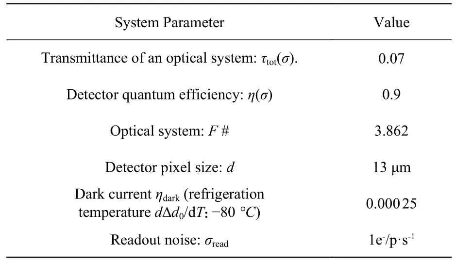
Tab.1 DASH system parameter list
2.3.2 Influence of SNR on wind speed accuracy
Noise is one of the important factors in reducing the quality of initial interferogram data.We conducted a simulation analysis on the variation process of wind speed error with SNR.
Firstly, an interferogram with a wind speed of 100 m/s was simulated, and different white Gaussian noise images were added to simulate the initial interferogram corresponding to the SNR of different values.Then, the inverse Fourier transform of the corresponding frequency spectrum was extracted by the Fourier transform and window function of the initial interferogram.The final wind speed was obtained by inversion.
In the inversion process, the Nuttall window function of the Gaussian window type with a small sidelobe effect was adopted.When selecting the width of the window function (FWHM, Full width Half Maximum), the spectrum after the Fourier transform should be considered as the convolution of the actual spectrum and the instrument’s linear function, which itself has a given width.Meanwhile,with a smaller window function width, there is a larger sidelobe in the spectrum and a larger distortion region after the convolution of the interferogram.With a wider window function width, there is more noise and a greater wind speed inversion error.In this paper, FWHM=10 and the wind speed obtained without noise inversion is 99.993 6 m/s.
The final influence curve of the SNR on wind speed accuracy was shown in Figure 6 (b).When the SNR is 0-60, the wind speed error is less than 10-4m/s.When the SNR is larger than 60, the wind speed error is almost 0.The SNR obtained by simulation in this paper is 113.75, so the interference fringe with high contrast can still be detected in a poor environment without a temperature control system.
2.4 Optical system design
For ground-based DASH interferometers, the imaging quality of the optical system has a significant impact on the entire DASH interferometer system.The optical system of the DASH interferometer includes entrance and exit optics.The entrance optics are located in front of the interferometer and are used to focus the source to be measured on the grating of the DASH.Exit optics are a transmission optical system with appropriate magnification and image quality, which can transmit the image of the interferogram to the detector.
2.4.1 Entrance optics
The magnification of the image-side telecentric optical path does not change with the position of the image plane, and the illumination of the image plane is uniform.To ensure the interference characteristics of the DASH system and uniformity of detector illuminance, an image-side telecentric optical system with a reasonable length was selected for the entrance optics.A narrowband filter was installed in front of the entrance optics to eliminate the signal in the excess spectral area outside the spectral range,and the signal light was transmitted into the interferometer by the entrance optics to be imaged on the gratings.To ensure that the interferometer can receive the target light flux, the entrance pupil diameter of the entrance optics was initially determined to be 40 mm, and the paraxial image height was -7 mm-7 mm.Based on the indicators above, an appropriate initial structure was selected and optimized.
The Modulation Transfer Function (MTF)curves of the entrance optics are shown in Figure 7.The MTF curve for each FOV was very close to the diffraction limit, and the imaging quality of the system was good.For the 550-560 nm band, the image-side telecentricity of the entrance optics was less than 0.006°, and the distortion was less than 0.05%.The design results met the design requirements, and the total length of the system was 252.8 mm, which is convenient for indoor and external field observation experiments.
2.4.2 Exit optics
The exit optics adopt a bilateral telecentric optical system structure.A feature of the bilateral telecentric optical system structure is that the incident parallel light ensures the system has a sufficiently large depth-of-field range, whereas the parallel light leaving the lens ensures that the working distance can vary greatly within the depth-of-field range and the magnification will not change.
The detector used in the system was a C-type interface, and the rear intercept should be greater than 25 mm.The image-side detector chip was 13.3 mm × 13.3 mm, and the effective width of the object-side grating was 13.69 mm × 13.69 mm.Then,the magnification was[25]
whereyandy′ represent the object-side and imageside field sizes, respectively.Applying Equation(28), the system magnification was -0.971 5.
To ensure the telecentricity of the system, software-related operands were used to control the angle of the deviating main ray from the optical axis.The telecentric degree should be as small as possible according to the design requirements of the telecentric system.In the optimization function setting, entrance pupil was set to 0.500, 0.707, and
1.000 to optimize the telecentric degree of the system.For a dual-telecentric lens optical system, distortion of the optical system distorts the interference fringe and reduces the measurement accuracy of the wind speed.Therefore, in addition to the above parameters, it is necessary to focus on optimizing the system distortion.
According to the Nyquist frequency formula,
As the detector pixel sizedwas 13 μm, the cutoff frequency should be greater than 38.46 lp/mm.At 38.46 lp/mm, the MTF of the exit optics was greater than 0.5[26].The MTF describes the relationship between the contrast of the object and the image at different spatial frequencies after the object passes through the optical system.The MTF is related to both the aberration of the optical system and its diffraction effects.This is an objective and reliable image quality evaluation method.The design results for the exit optics are shown in Figure 8 and Table 2.
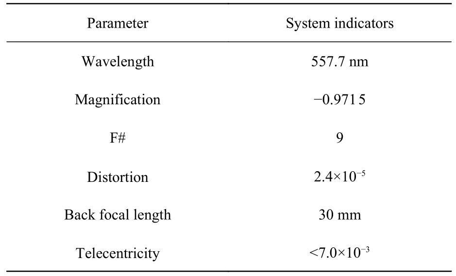
Tab.2 Design indices of the dual telecentric optical system
In the measured target band, the MTF of the entrance and exit optics was close to the diffraction limit, which offers good imaging quality and satisfies all of the indicators.Two optical systems and interference modules were placed into the same system via software, and the image plane of the entrance optics (the end grating surface of the two optical paths) was successfully matched with the object plane of the exit optics (the end grating surface of the two optical paths).Two-dimensional and three-dimensional images of the system are shown in Figure 9 (a) and 9 (b).The surfaces of all lenses of the two optical systems were spherical,making them easy to process.Considering the thermal difference and economic conditions, reasonable materials were selected to produce the real object.
3 Experimental verification
3.1 Verification results
To verify whether the design results meet the requirements of ground-based detection and whether the ground-based DASH interferometer can receive a sufficient etendue and SNR, an experimental platform for the indoor DASH interferometer was constructed based on the design results.A physical diagram of the interferometer is shown in Figure 10,and the basic parameters are shown in Table 3.The specifications of DASH system are shown in Table 4.One optical path of the grating was glued,and the other optical path required experimental debugging.

Tab.3 Basic parameters of DASH interferometer
Krypton lamp emission light contains a 557.0 nm emission line, and the light intensity is weak.Therefore, a krypton lamp could be used to simulate the airglow spectrum after passing through the narrowband filter in the laboratory experiment.The narrowband filter is shown in Figure 11.The narrowband filter diameter was 50 mm, the thickness was 5 mm, the material was fused quartz, the central wavelength was 557.7 nm, the bandwidth was 3 nm,and the peak transmittance was no less than 95%.

Tab.4 DASH system specifications
The laboratory experimental platform is shown in Figure 12 (a) and (b).The target light emitted by the krypton lamp was transmitted through the optical fiber into the collimation system.The collimated target light was semi-inverse and semi-permeable to the wind speed simulator owing to beam splitter 1.The wind speed simulator was driven by a motor with a turntable attached with reflective film, so that the incident light was reflected into the entrance optics with a narrow-band filter after the frequency shift.The signal was imaged on the two gratings of the interference module by the entrance optics, and the interference fringe was formed by the interference module.The interference fringe was scaled and imaged on the detector using the exit optics.
The DASH interferometer uses an absolute phase to invert the wind speed differentially.The Littrow angle is key to determining the spatial frequency and phase of the interferogram.Therefore,an accurate Littrow angle assembly is crucial to the accuracy of wind speed measurements.The krypton lamp was used as the light source, and the grating Littrow angle was finely tuned mechanically.The krypton light source, with a wavelength of 557.0 nm, formed interference fringes through the interferometer that were received by the detector.The interference pattern is shown in Figure 13.Because the krypton lamp was relatively bright compared with the gas glow, the integration time in the laboratory experiment was only 1/60 that of the ground experiment, which was too small and lead to a transverse bright line in the detector that was unrelated to the interferogram.It was preliminarily proven that the interference module and optical system were reasonably designed.
Laboratory debugging experiments have proven the feasibility of using krypton lamps as the light source for DASH interferometer detection.On this basis, the DASH interferometer was glued to an integrated system with a stable structure and mounted on a tripod with an adjustable pitch angle, as shown in Figure 14.Ground-based detection experiments were conducted using night airglow as the detection target.
Because the brightness of night airglow is very low, the detection distance is large, and stray light may also affect the experimental results in an environment with as high air transmittance as possible.Therefore, a field with almost no stray light was selected to conduct the ground-based detection experiment under sunny and cloudy weather conditions.The outdoor ground-based experiment was carried out in Changchun, China, on May 14, 2022, and a photograph of the experimental setup is shown in Figure 15.On the day of the experiment, the weather was clear with a full moon.In order to avoid the influence of moonlight as background light, a narrowband filter was still used in front of the optical system to filter out most of the background light.The measurement time was selected to be 9 p.m.Beijing time when the moon had not fully risen to its zenith and rested instead at 45° to that.The device faced away from the moon, toward the darkest part of the sky at an elevation of 70 degrees.During the detection process, the integration time was 60 s.At the same time, an EMCCD with refrigeration and gain functions was selected.The cooling temperature was -70 °C and the gain was 20 to ensure that the influence of background light was minimized.The interference fringe is shown in Figure 16.
On this basis, we also conducted several experiments, among which the indoor and external interference graphs are obtained on September 27, 2022.They are shown in Fig.17 and Fig.18.
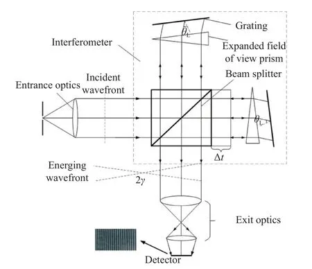
Fig.1 Diagram of the DASH interferometer structure

Fig.2 Curves of the modulation and phase difference varying with optical path difference of the 557.7 nm spectral line at 90-110 km
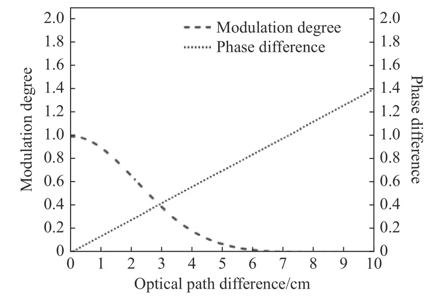
Fig.3 Curves of the modulation and phase difference varying with optical path difference of the 557.7 nm spectral line at 150-300 km

Fig.4 Plot of the optical path difference versus the interferogram intensity difference

Fig.5 Optical path diagram of the interference module

Fig.6 (a) Relationship between signal to noise ratio and pixel position; (b) graph of variation of wind speed error with SNR

Fig.7 The MTF curves of the entrance optics

Fig.8 (a) MTF of the exit optics and (b) dot chart of the exit optics

Fig.9 (a) Two-dimensional system diagram; (b) three-dimensional system diagram

Fig.10 Real image of the interferometer
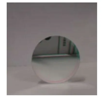
Fig.11 Real image of the narrow band filter

Fig.12 (a) Schematic diagram of the laboratory debugging device; (b) photograph of the laboratory debugging device

Fig.13 Streaks made by krypton lamps in the laboratory

Fig.14 Integrated ground-based DASH interferometer

Fig.15 Photograph of the ground experiment setup

Fig.16 Night airglow interferogram

Fig.17 Interferogram of krypton lamp on September 27
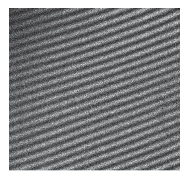
Fig.18 Interferogram of night airglow on September 27
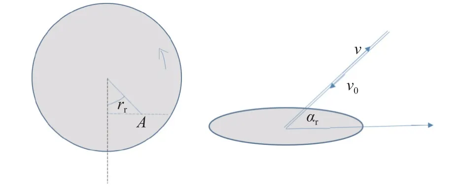
Fig.19 Schematic diagram of wind speed simulation
However, there were angle differences between the stripes measured in the indoor and outdoor experiments, and the reasons are analyzed as follows:
(1)The bump in the transportation process would cause a slight deviation of Littrow angle.After the temperature control system is improved,the system will be reinforced to avoid this problem.
(2) There was a gap between the indoor and outdoor temperatures, and the system was very sensitive to temperature.There was no temperature control system at that moment.To improve the temperature control system, this problem could be avoided.
The obvious interference fringes shown in Figures 16-18 prove that the system design results of the DASH interferometer are reasonable, and the signal-to-noise ratio and luminous flux of the system meets the detection requirements, verifying the feasibility of ground-based detection of the DASH interferometer.
On this basis, we will invert the interference fringes measured in the laboratory.The speed of the beam carried by the krypton lamp and the wind speed simulator is:
whereNsis the rotating speed of the turntable of the wind speed simulator,ris the distance from the round point of the turntable of the wind speed simulator,αris the angle between the beam and the reflecting disk, andrris the angle from the vertical direction.Schematic diagram is shown in Figure 19.
When the rotational speed is 1 810, 2 021 and 2 203 r/min, the simulated wind speed is 37.527,41.9 and 45.675 m/s, respectively.The corresponding interference diagram is shown in Fig.20.

Fig.20 The corresponding interferogram is 1 810, 2 021 and 2 203 r/min, respectively
The measured interference fringe pattern shown in Fig.20 is preprocessed, and the average phase difference obtained by inversion is 0.087,0.148 7 and 0.221 8 rad, respectively.The corresponding wind speed is 66.425, 113.1 and 168.7 m/s.
Due to the lack of calibration, the accurate phase of fundamental frequency cannot be obtained for the time being.During the experiment, the ambient temperature changes greatly and exceed the ambient temperature required by the experiment(20 °C±0.1 °C).Moreover, the wind speed simulator will also produce errors, resulting in the measured wind speed errors.Although the wind speed error is large, the wind speed obtained by inversion is within a reasonable range and the function of the principle verification level of the interferometer can be verified.
4 Conclusion
Based on the characteristics of the 557.7 nm oxygen green atom airglow spectral line, a ground DASH interferometer was developed, its design scheme was formulated, and the parameters of its interference module were calculated.Simultaneously, the optical system of the DASH interferometer was designed.The system entrance and exit optics were optimized with the image telecentric mirror group and double telecentric mirror group as initial structures.In the target band, the image telecentric degree of the entrance optics was less than 0.006°,and the distortion was less than 0.05%.The image square and object square telecentricity of the exit optics were both less than 7.0 × 10⁻³, the distortion was less than 2.4 × 10⁻⁵%, the Nyquist space frequency was 38.46 lp/mm, the MTF was greater than 0.5,and all indicators met the requirements.Compared to other passive wind measuring systems, this system has a large FOV and is designed for thermal dissipation.The half-field angle reached 2.815°, the system SNR was approximately 113.75, and the etendue was approximately 0.095 25 cm2sr.Clear interference fringes were detected in both indoor and outdoor experiments, which proves that the groundbased DASH interferometer with thermal compensation and high SNR and large etendue meet the requirements of ground-based detection, and the feasibility of DASH interferometer ground-based detection is verified.

