Experimental research based on a C-band compact transit-time oscillator with a novel diode loading an embedded soft magnetic material and shielding structure
Yufang He(何宇放), Juntao He(贺军涛), Junpu Ling(令钧溥), Lei Wang(王蕾), and Lili Song(宋莉莉)
College of Advanced Interdisciplinary Studies,National University of Defense Technology,Changsha 410073,China
Keywords: high-power microwave,soft magnetic material,shielding structure,transit-time oscillator
1.Introduction
Driven by application requirements, miniaturization and compactness have become important development directions of high-power microwave(HPM)sources.Reducing the external guiding magnetic field is an effective way to achieve this objective.In recent years, there have been many research reports in this area.[1–16]A transit-time oscillator(TTO)is a type of HPM source that has the potential to be miniaturized and compact due to its simple structure,which can work efficiently with a low external guiding magnetic field.This kind of device has attracted increasing interest from researchers.[6,17–25]In recent years,research on TTOs with a low external guiding magnetic field has achieved many results.
Previously, our research group proposed a novel C-band TTO in simulation studies.[26]The design purpose of this device was to obtain a lightweight and compact HPM device,so we chose a low external guiding magnetic field.In the previous study, this device showed its advantages in reducing the external magnetic field.If the efficiency of the device can be further improved,the advantage will be more obvious.During a series of studies, it was found that when the device works with a low magnetic field, the quality of the intense relativistic electron beam (IREB) is relatively low, so the conversion efficiency is affected to a certain extent.In order to ensure the miniaturization and compactness of the device,we hope to further improve the conversion efficiency of this C-band TTO without increasing the applied magnetic field.It is very meaningful to explore how to improve the quality of the IREB with a low external guiding magnetic field, thereby improving the conversion efficiency of the HPM source.Therefore, a novel highly efficient diode in our manuscript is designed in this case for better beam quality in the presence of a low external guiding magnetic field.
This paper mainly introduces a diode with shielding structures and embedded soft magnetic material, and experimental research on HPM generation on the C-band TTO with this novel diode.Section 2 introduces the theoretical analysis of the transmission of an IREB with a low external guiding magnetic field.Section 3 introduces the design and simulation study of the novel diode.Section 4 presents the experimental study of HPM generation on the C-band TTO with the novel diode,and Section 5 concludes this paper.
2.Analysis of IREB propagation with a low guiding magnetic field
Usually, in the inner part of HPM devices, when loading an intensive external guiding magnetic field,the constraining force of the magnetic field can be balanced with the space charge force of the IREB itself.However, when the magnitude of the magnetic field is decreased, the fluctuation of the electron beam is significantly enhanced,which affects the conversion efficiency of the HPM device.
The propagation of an annular IREB in a coaxial waveguide is shown in Fig.1.Its transmission equation can be expressed as[27]
whererbis the radius of the annular electron beam,γis the relativistic factor,mis the mass of the electron,estands for charge of an electron,pθ=mΩcr2c/2 is the canonical angular momentum,rcis the cathode radius,Ωcis the electron cyclotron frequency in the region of the cathode,andΩ=eBz/mis the electron cyclotron frequency.
Equation (1) can be solved to obtain the equilibrium radius of the electron beamrb0.The radius of the annular electron beam can be expressed as
Here,δris the fluctuation value of the electron beam radius.Substituting Eq.(2) into Eq.(1) and converting thetcoordinate system to thezcoordinate system, it can be obtained that[27]
wherek1,k2andk3are all constants.The general solution to Eq.(3)is[27]
It can be found from Eq.(2)that[27]
From the above analysis,the maximum radius of electron beam fluctuation isrmax=rb0+A,whereAis determined by the initial conditions.This means that the maximum radius of the IREB radial fluctuation in the transmission process is determined by the maximum radius of the IREB in the diode.
When the electron beam is in the diode,the transmission equation is rewritten as[27]
In the diode,the electron beam is not only subjected to its own space charge repulsion, the Lorentz force from the external magnetic field,and the self-pinch force generated produced by a self-magnetic field,but also the radial electric field force generated by the two-dimensional space structure.Among them,Er1represents the radial electric field introduced by the twodimensional space structure of the diode.The gravitational component is
The repulsive component is
Due to the radial electric field force in the diode region, the equilibrium radius of the electron beam in the diode regionrb1is larger, that is,rb1>rb0.Especially when the external guiding magnetic field is lower, the magnetic field force represented by Eq.(7) is weaker, and the equilibrium radius is further enlarged, resulting in greater fluctuation of the IREB,which affects the efficiency of HPM generation of our designed TTO.
From the above analysis,in order to obtain an IREB with a smaller radius and improve the emission and transmission quality, it is necessary to strengthen the gravitational component (Eq.(7)) in the diode region and reduce the repulsive force (Eq.(8)).That is to say, we must find a way to reduceEr1while addingBzin the diode region.
Therefore, we designed a novel type of diode with embedded soft magnetic material and shielding structures.The introduction of soft magnetic material can enhance the local guiding magnetic field in the diode region, and the shielding structure can effectively weaken the radial electric field introduced by the two-dimensional spatial structure.This diode can emit an electron beam with less fluctuation while maintaining a low external magnetic field, which improves the emission and transmission quality of the electron beam.We describe the design in the subsequent sections.
3.Design of the novel diode and simulation investigation
In a previous study, we proposed a C-band coaxial TTO capable of operating under low magnetic field conditions.In the simulation study,[26]when the external guiding magnetic field was 0.4 T,with a diode voltage of 548 kV and a current of 11.4 kA, an HPM output of 1.88 GW was generated and the microwave frequency was 4.27 GHz.The beam conversion efficiency was calculated as about 30%.We found that the device has the potential to work with low magnetic field by loading opening foils.However,the problems of low beam emission and transmission quality caused by the low magnetic field were not completely solved.In the condition of a low external guiding magnetic field,the electron beam may bombard the surface of the foils to generate plasmas, which influences the working efficiency of the device.Therefore,the device has to be further optimized.
After multiple simulation optimizations, combined with theoretical analysis,a high-power diode with a shielding structure and embedded soft magnetic material is proposed,which is loaded into the original TTO structure as shown in Fig.2.

Fig.2.The C-band coaxial TTO loaded with the novel diode.
The beam-wave interaction area of the coaxial TTO is composed of a two-cavity buncher, a single-cavity extractor and opening foils.The opening foils are used to enhance the guidance of the electron beam while avoiding the plasma generated by the electron beam bombardment.The coaxial output port is used to output HPMs,and the electron collector adopts an inclined surface structure.In the diode region,as shown in Fig.2,a shielding structure is used to reduce the radial electric field and a soft magnetic material is embedded in the cathode holder, which clings to the cathode end to improve the emission quality of IREB by increasing the local magnetic field.The soft magnetic material is 6 mm long and 3 mm wide.
A simulation study on the enhancement of the local magnetic field by the soft magnetic material is carried out.Poisson Superfish is applied to simulate the magnetic field in our design.It uses the finite element method which can accurately simulate the parameters of the magnetic field.The configurations of a solenoid generating a 0.3 T magnetic field before and after loading the soft magnetic material are compared.As shown in Fig.3(a), the addition of the soft magnetic material changes the local magnetic field configuration.The soft magnetic material produces a local magnetic field enhancement so that the magnetic field lines gather near the soft magnetic material,so the local magnetic field line density increases.
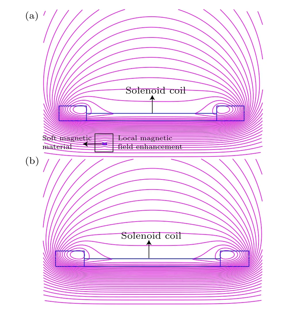
Fig.3.Comparison of the configuration of the magnetic field.(a)Magnetic field loading a soft magnetic material.(b)Magnetic field without a soft magnetic material.
Furthermore, in the simulation optimization, the influence of various parameters of the soft magnetic material on the magnitude of the axial magnetic field at the cathode head is studied,as shown in Fig.4.The distance in Fig.4 represents the distance between the right surface of the soft magnetic material and the left surface of the graphite cathode embedded in the cathode rod.Bzrepresents the axial magnetic field at the cathode head.The width represents the width of the soft magnetic material.In the simulation study,when the width is changed, the central axis of the soft magnetic material is always consistent with that of the graphite cathode.It can be seen from the figure that when the distance increases,the local magnetic field enhancement effect of the soft magnetic material weakens.The magnetic field at the cathode head gradually decreases from the highest 0.39 T to the origin 0.3 T magnetic field generated by the solenoid coil.Therefore,the soft magnetic material should be placed close to the graphite cathode as shown in Fig.2.In order to ensure the consistency of the experiment and simulation,the soft magnetic material should not be too close to the cathode head to ensure that the graphite can be embedded in the cathode holder.Therefore, the graphite cathode is embedded in the cathode holder by 1 mm,the outer exposed part is about 2 mm,and the soft magnetic material is 3 mm away from the cathode head,that is,when the distance is 0 in Fig.4.
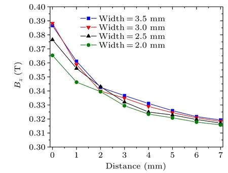
Fig.4.Influence of soft magnetic material parameters on the magnetic field of cathode head.
At the same time, the width of the soft magnetic material is analyzed.It is found that when the width is 3 mm,the magnetic field at the cathode head has a maximum value of 0.388 T.When the width of the soft magnetic material increases, the magnetic field increases significantly, but the increase is not obvious when the width exceeds 3 mm.The volume of the soft magnetic material should not be too large, so a soft magnetic material with a width of 3 mm and a length of 6 mm is used.
Taking the cathode head as the origin, the magnitude of the axial magnetic field near the cathode head is extracted as shown in Fig.5.The axial magnetic field is significantly improved near the cathode head,from 0.3 T to about 0.388 T at the highest.According to previous theoretical analysis,the enhancement of the local magnetic field in the diode region can improve the quality of electron beam emission and transmission in the whole device.
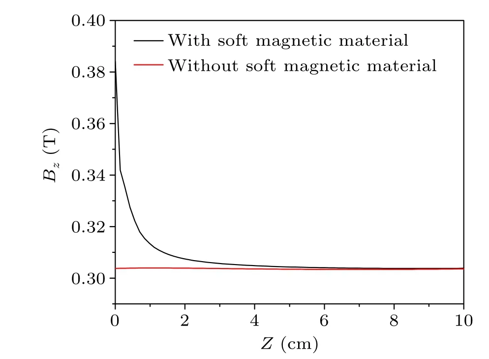
Fig.5.Comparison of the axial magnetic field near the cathode head.
The introduction of the shielding structure is to reduce the radial electric field in the diode region and to focus the electron beam.For traditional annular cathodes,radial electric field is unavoidable.The effect of radial electric field is more pronounced when the device is operated with a low external guiding magnetic field.Therefore,we adopt the shielding structure as shown in Fig.2 to solve this problem.
The decrease in the radial electric field in the diode region by the shielding structure is analyzed by simulation,as shown in Fig.6.From Fig.6(b), both sides of the cathode head are wrapped by shielding structures with a thickness of 3 mm.At this time,the radial electric field near the cathode head is suppressed, which helps to improve the electron beam emission and transmission quality.
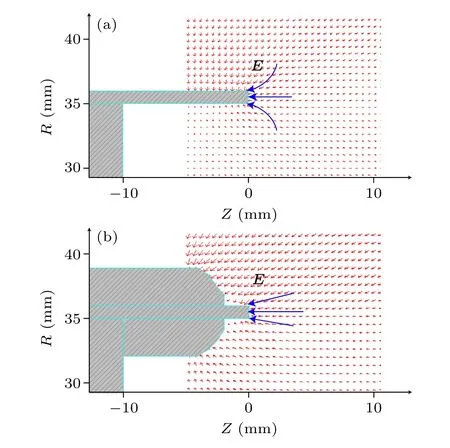
Fig.6.The electric field distribution of two types of diode.(a)Conventional diode.(b)Diode with shielding structure.

Fig.7.Simulation model and comparison of the thickness of the IREB.(a) Simulation model of TTO with novel diode.(b) Simulation model with traditional diode.
In order to verify the effect of the novel diode, a simulation study of HPM generation is carried out, as shown in Fig.7.Figure 7(a) is a schematic of the simulation model when loading a new type of diode,and figure 7(b)is that when loading a traditional cathode.Through the measurement of the beam thickness,it is found that the maximum thickness of the electron beam with the novel diode in the diode region is only 2.8 mm,while the value for the traditional structure is 7.1 mm.This shows that the novel diode can significantly improve the emission and transmission quality of an IREB with a low magnetic field.
In our simulation study, with an external guiding magnetic field of 0.3 T,a diode voltage of 542 kV and a diode current of 9.2 kA, the C-band TTO loaded with the novel diode outputs HPMs of 1.83 GW with a frequency of 4.27 GHz,and the conversion efficiency can be calculated as about 36.7%.The output microwave power and frequency are shown in Figs.8 and 9, respectively.Compared with the previous research by our research group,the conversion efficiency is 30%with an external magnetic field of 0.4 T.Therefore,the structure loaded with the novel diode can achieve higher efficiency even with a lower magnetic field.
To further verify the effect of this diode, we present our experimental studies in the following section.
4.Experimental research
Previously, we preliminarily demonstrated the effect of the novel diode through simulation studies.In order to further verify the reliability of the diode,based on the platform of the C-band TTO,we conduct an HPM generation experiment.
4.1.Experimental system
Figure 10 shows the internal assembly structure of the beam-wave interaction area of this experiment.The shielding structure in the diode is still made of stainless steel, the cathode material is graphite,and the embedded soft magnetic material is industrial pure iron DT8.The embedded design of the soft magnetic material enables the stainless steel wrapped outside the soft magnetic material to effectively prevent the breakdown of the soft magnetic material and maintain the vacuum degree of the device.The experimental device is shown in Fig.11.In the experiment,a solenoid coil is used for generation of the magnetic field.The vacuum pump is used to maintain the vacuum environment inside the device.We choose a horn antenna for the radiation of HPMs,and the HPM source is the same as the C-band coaxial TTO shown in Fig.2.Fig.10.Internal assembly structure of the experiment.(1) Cathode holder.(2)Soft magnetic material.(3)Graphite cathode.(4)Inner conductor.(5) Dual-cavity buncher.(6) Opening foils.(7) Single-cavity extractor.(8) Electron collector.(9) Output waveguide.(10) Shielding structure.(11)Solenoid coil.
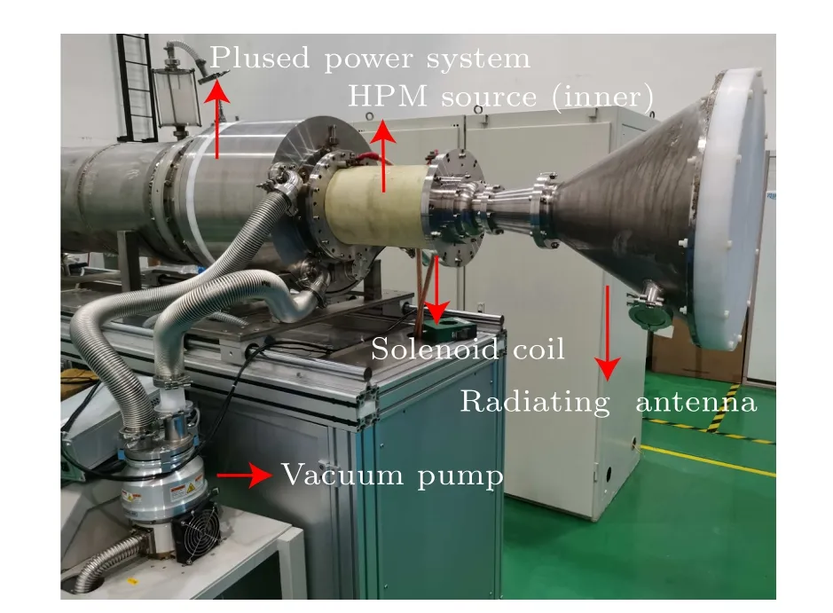
Fig.11.The experiment device.
Far-field measurement method is applied to measure the radiated HPM.Figure 12 shows the layout of HPM measurement.Two receiving horn antennas are symmetrically distributed to the radiating antenna.They receive HPM radiation respectively,and the symmetry of the radiation is analyzed by their comparison.

Fig.12.Layout of HPM measurement.
During the experimental assembly, the coaxiality of the inner and outer conductors should be ensured.Mismatches in assembly can cause inconsistencies between experiments and simulations.In addition,close observation is required because the shielding structure is very prone to breakdown, resulting in beam loss.
4.2.Experimental results
When the solenoid coil generates a 0.3 T external guiding magnetic field,the diode voltage is 540 kV,and the current is 10.5 kA, the diode voltage and current are shown in Fig.13 and the HPM signal is shown in Fig.14.When loading the novel diode,an output HPM power of 1.51 GW is obtained and the corresponding conversion efficiency is 26.6%.In contrast,when loading a conventional diode,the output HPM power is only 1.13 GW with a conversion efficiency of 20.0% under the same input power and external magnetic field.The measured microwave frequency is shown in Fig.15.The output frequency is 4.27 GHz.
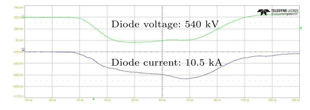
Fig.13.Diode voltage and current of the experiment.
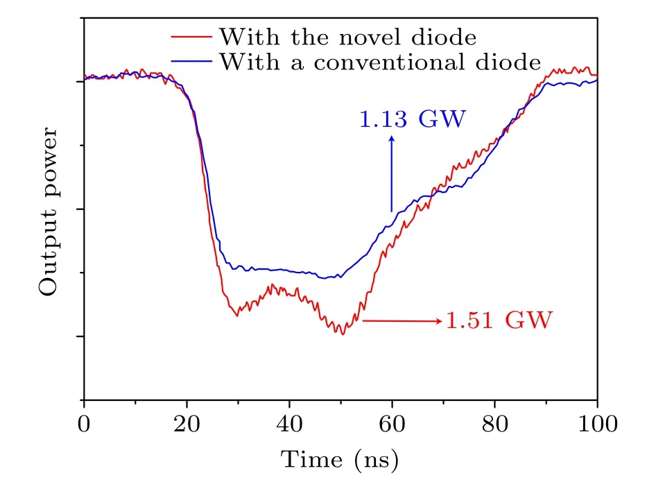
Fig.14.Output HPM of the experiment.

Fig.15.The spectrum of the output microwave.
4.3.Analysis and discussion
Compared with the simulation results, the frequency of the experimental study is consistent.The experimental results prove the improvement in the device efficiency.The conversion efficiency of the device loaded with the novel diode is improved by about 6.6%.However,the output power and conversion efficiency in the experiment are not consistent with the simulation results.After disassembling the device, no breakdown of the cathode holder is found.However,it is found that some electron beam bombardment traces appear near the cathode head,as shown in Fig.16.These bombardment traces inside the cathode are caused by backflow electrons,resulting in beam loss,which causes the difference between the efficiency of the experiment and the simulation.In addition, errors due to device assembly are also one of the reasons.We will find ways to solve these problems in future work.
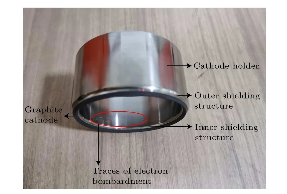
Fig.16.The cathode after experiment.
5.Conclusion
In this paper,we study the method of improving the conversion efficiency of a C-band coaxial TTO with a low external guiding magnetic field through theoretical analysis,simulation research,and experimental verification.We proposed a novel diode with embedded soft magnetic material and a shielding structure to improve the efficiency of TTO and verify its ability.The research in this paper shows that the novel diode enables the C-band TTO to work with higher efficiency even with a lower magnetic field, and achieves great results.However,there is still a gap between the simulation efficiency and the experimental efficiency.We will propose further improvement methods for this problem in the future.
Acknowledgments
Project supported by the National Natural Science Foundation of China(Grant No.61701516).We would like to show our deepest gratitude to the colleagues that offered us help in our research.
- Chinese Physics B的其它文章
- First-principles calculations of high pressure and temperature properties of Fe7C3
- Monte Carlo calculation of the exposure of Chinese female astronauts to earth’s trapped radiation on board the Chinese Space Station
- Optimization of communication topology for persistent formation in case of communication faults
- Energy conversion materials for the space solar power station
- Stability of connected and automated vehicles platoon considering communications failures
- Lightweight and highly robust memristor-based hybrid neural networks for electroencephalogram signal processing

