Research on Channelization Techniques of Radio Astronomical Wideband Signal with Oversampled Polyphase Filter Banks
Meng Zhang ,Hai-Long Zhang ,Ya-Zhou Zhang ,Jie Wang ,Shao-Cong Guo ,and Qiao Meng
1 Xinjiang Astronomical Observatory,Chinese Academy of Sciences,Urumqi 830011,China;zhanghailong@xao.ac.cn
2 University of Chinese Academy of Sciences,Beijing 100049,China
3 Key Laboratory of Radio Astronomy,Chinese Academy of Sciences,Nanjing 210008,China
4 National Astronomical Data Center,Beijing 100101,China
5 School of Information Science and Engineering,Southeast University,Nanjing 211100,China
6 School of Cyber Science and Engineering,Qufu Normal University,Qufu 273165,China
Abstract Digital channelization decomposes a wideband signal into multiple adjacent sub-bands using Parallel Technology.Channelization can effectively reduce the pressure on the radio astronomy digital backends system and make wideband signal processing possible.Aiming at the problems of signal attenuation at sub-band edge,spectral leakage and aliasing encountered in wideband signal channelization,algorithms to reduce the problems are studied.We design a Critically Sampled Polyphase Filter Bank (CS-PFB) based on the Finite Impulse Response digital filter with a Hamming Window and systematically analyze the frequency response characteristics of the CS-PFB.Based on the channelized structure of the CS-PFB,an OverSampled Polyphase Filter Bank(OS-PFB)is designed by data reuse,and the filtering frequency response characteristics of CS-PFB and OS-PFB are compared and analyzed.Using the wideband baseband data generated by the CASPSR (Collaboration for Astronomy Signal processing and electronics research Parkes Swinburne Recorder),we implement sub-band division and 16-band output of these data based on the 2×oversampling OS-PFB,and the problem of spectrum inversion in the subbands is corrected.After removing 25%of redundant data in the head and tail of each sub-band,we recombine the sub-bands into a wideband.The wideband signal is almost identical to the original observed signal.Therefore,the experimental results show that the OS-PFB can improve the channel response.For the 400 MHz baseband data of J0437-4715,we compare the pulse profile obtained from the original baseband data with the pulse profile obtained after the channelization and recombination.The phase and amplitude information of the pulse profiles are consistent,which verifies the correctness of our channelization algorithm.
Key words: (stars:) pulsars: general– methods: analytical– miscellaneous– methods: data analysis
1.Introduction
With the increasing bandwidth of receiving systems in communication and astronomy,radio telescopes need to be equipped with high performance digital backends.The digital backends analyze and process streaming data in real-time with high bandwidth,high time,and high frequency resolution.As a key technique for wideband signal processing,channelization divides the wideband signal into multiple sub-bands which are adjacent to each other.The signal processing of multiple relatively narrow sub-bands can effectively reduce the system pressure and improve the efficiency of wideband signal processing.
In the process of channelization,the problems of spectrum leakage,sub-band aliasing,and sub-band edge signal attenuation are easy to occur (Kong et al.2020).Choosing an appropriate channelization method can effectively improve the channel response.Channelization methods include Discrete Fourier Transform (DFT),FIR digital filter,binary tree structure,Polyphase Filter Bank (PFB),and so on (Sudharman et al.2019).DFT is often implemented by the Fast Fourier Transform(FFT)algorithm,which has high inherent spectrum leakage and cannot achieve high precision channelization (Harris &Haines 2011).Multi-channel filter banks with uniform bandpass width and consistent filtering characteristics can be designed by FIR digital filter.In order to obtain ideal channelization results,higher FIR filter order is required,which requires huge hardware computing resources.Binary tree structure uses digital downconversion and down-sampler cascade repetition to cut the input bandwidth by half,which reduces the computational complexity but lacks flexibility (Ghandour et al.2020).
Digital filter bank(Proakis 2001)is an effective way to divide the wideband signal into multiple sub-bands.Each sub-filter of a uniform filter bank has the same passbandwidth,and the signal is decomposed into several sub-bands with the same bandwidth and sampling rate,which occupy the corresponding frequency band.PFB (Harris 2021) is an analysis digital filter bank optimized by the standard uniform digital filter bank.With the help of decimation/interpolation,the serial channelization process can be decomposed into a parallel multiplexing process.PFB uses multiple low-order sub-filters to realize the original high-order filtering,and the data processing rate of each subfilter is significantly reduced,which can realize channelization more efficiently.The PFB structure can be optimized by using a window function in front of the DFT,which can reduce the spectrum leakage between sub-bands.However,it is necessary to truncate some sub-bandwidths or design a higher-order lowpass prototype filter to minimize aliasing.To avoid reducing the available signal bandwidth or increasing the order of the prototype filter and to solve the aliasing between adjacent subbands,we can achieve channelization by using an OS-PFB(Bunton 2003) to obtain a flatter overall bandpass response.
Price (2021) used the Hanning window function with large side-lobes attenuation to construct a channelizer and spectrometer based on PFB.To reduce energy leakage,the correlator on the Tianlai Dish Array uses PFB to channel the input data stream (Niu et al.2019).Hobbs et al.(Hobbs et al.2020) designed an FIR filter,which uses a least squares algorithm with a Kaiser window function and has a passband ripple of ∼0.02 dB with a transition at the band edges crossing the adjacent sub-band at −6 dB.Hobbs designed two critically sampled channelizers for different sampling rates,one with 16 output sub-bands and 1024 coefficients,the other with ten output sub-bands and 640 coefficients.Hobbs planned to use OS-PFB for later stages to eliminate sub-band edges aliasing further.Morrison et al.(Morrison et al.2020)used OS-PFB to realize channelization and inversion,and they described the influence of OS-PFB on the inversion accuracy.Tuthill et al.(Tuthill et al.2015) described the OS-PFB channelizer of the Australian Square Kilometer Array Pathfinder (ASKAP) radio telescope.They presented a technique for correcting sub-band frequency shifts caused by oversampling.Smith et al.(Smith et al.2021) designed and implemented an oversampled polyphase channelizer to handle 4 GHz instantaneous bandwidth.Our study focuses on solving the problems of spectrum leakage,sub-band edge signal attenuation,and aliasing from channelization of baseband data in radio astronomy using CSPFB and OS-PFB.
This paper introduces the principles of CS-PFB and OS-PFB of FIR digital filter based on window function in detail.We compare the frequency response characteristics of the CS-PFB and the OS-PFB,realize channelization of the baseband data of Parkes-CASPSR backends (Sarkissian et al.2011),and recombine the sub-bands to form a complete wideband.Experimental results show that our oversampling channelization method can improve the channel response.We are releasing our implementation as open-source6https://github.com/MengZZZUCAS/PFBfor further research and use to implement high-precision channelization.Our research can provide a high-precision channelization method for pulsar timing and molecular line observation.
2.PFB
PFB can be formed by adding FFT after a set of polyphase FIR filters,and it can effectively realize spectrum shifting,filtering,and resampling during channelization.7https://casper.astro.berkeley.edu/wiki/The_Polyphase_Filter_Bank_TechniqueThe design of the PFB relies on Noble identity,i.e.,the filterH(zM)followed by a down-sampler gives the same output as a down-sampler followed by the filterH(z),as shown in Figure 1.HereDtimes down-sampler means that each channel only uses theDth sample of each set of data.Moving the down-sampling operation to the front of the filter reduces the rate by a factor ofD,which improves the computational efficiency.This change requires modifying the filter coefficients and decomposing them so that each set of samples can be operated in parallel.

Figure 1.Noble identity.
In this paper,the number of channels is represented byMand the decimation factor is represented byD.PFB can be classified as CS-PFB (or maximally decimated PFB) and OSPFB (or non-maximally decimated PFB) whenM=DandM>D,respectively.
2.1.CS-PFB
When the decimation factor (D) equals the channel number(M),the PFB is known as CS-PFB.The number of polyphase components determines the down-sample factor (D).The CSPFB providesMinput samples forMchannels in each unit of time,the basic structure is shown in Figure 2,including three parts.(1) The delay and down-sample can form an input commutator,which decomposes the input sequence intoDgroups and assigns the data toDsub-filters of the same order;(2) Polyphase decomposed FIR filters convolve the decomposed data sequence on each path to achieve filtering;(3)D-point DFT or IDFT,which can be efficiently implemented using FFT or IFFT.
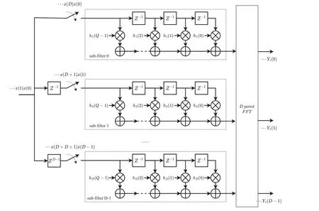
Figure 2.CS-PFB structure.
Polyphase decomposition is the core of CS-PFB,which decomposes the input sequence and prototype filter coefficients into multiple branches.CS-PFB provides an efficient filter implementation that requires fewer multiplications and additions per unit time than conventional filter banks.For theN-order filter,theM-stage polyphase implementation requires only (N+1)/Mmultiplications andN/Madditions per unit time,and the input data are processed in parallel at a lower sampling rate.For the polyphase decomposition of the original input sequence,the input datax(m) can be decimated byDtimes to generateDgroups of samplesxD(m).After grouping,each branch can be convolved by each sub-filter respectively.Figure 3 shows the polyphase decomposition withD=3,which decomposes the input sequence (a) into(b),(c),and (d).

Figure 3.Polyphase decomposition of the input data.

Figure 4.Polyphase decomposition of the prototype filter coefficients.
After the completion of the polyphase decomposition,the filter coefficients and input data are rearranged,which is manifested as the inversion of the input data matrix or filter coefficient matrix.The corresponding structure of the final input data and coefficients is shown in Figure 5.

Figure 5.The corresponding structure of input data and coefficients.
After performing the polyphase decomposition and rearrangement of the filter coefficients and input data,the convolution operation is performed on the data of each channel separately.The data and the filter coefficients of each branch are shifted,multiplied,and added.The results are multiplied by the complex exponential(−1)dejπd/Dto make the phase alignment,offset the aliasing caused by down-sampling,and then perform FFT.
For the CS-PFB structure in Figure 2,due to the conjugate symmetry property,if the input data areDpoints real numbers,the output isD/2 valid points,namelyD/2 valid channels;if the input data areDpoints complex numbers,the output isDvalid points,namelyDvalid channels.
We assume the input sample frequency of an input wideband signal isfs,the CS-PFB executesM-point FFT and producesMFFT bins with bandwidthfs/M.The output sampling rate is reduced tofs/M.In this case,there are problems of sub-bands attenuation or spectrum aliasing.Figure 6(a)shows that the transition band crosses the Nyquist bandwidth.The transition band attenuation of the signal is therefore shown,as circled in the ellipse,and part of the signal is lost at the band edge.The shaded part of the transition band is mixed into its adjacent channels,resulting in spectrum aliasing.In Figure 6(b),the transition band is designed to fall entirely within the Nyquist bandwidth,that is,the Nyquist bandwidth is equal to the sub-channel bandwidth.Here adjacent sub-bands aliasing is eliminated,but at the cost of signal attenuation at the band edge.The above problems will be solved by oversampling the input data.

Figure 6.Sub-channel passband at different sample rates.
2.2.OS-PFB
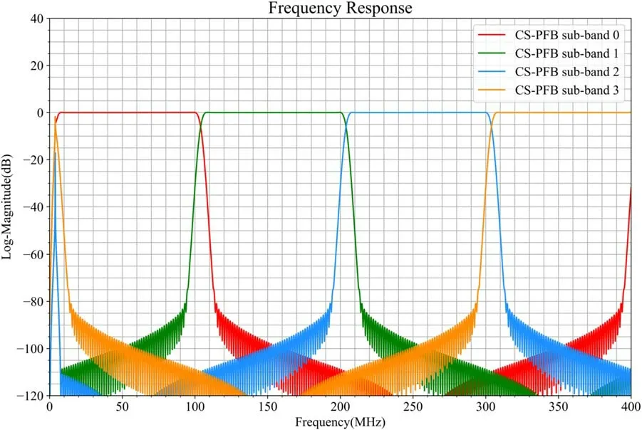
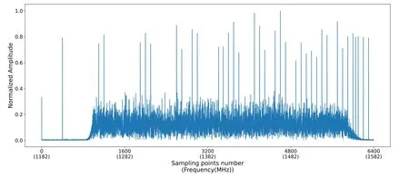
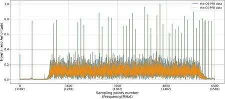
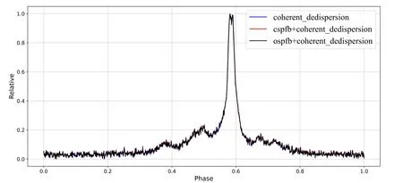
OS-PFB is an extension of the CS-PFB algorithm,and its composition structure is similar to CS-PFB,including delay,down-sample,FIR filter,and FFT/IFFT.The down-sample is put in front of the filter bank by Noble identity.Figure 7 shows theM-channels channelization with decimation factorD,in whichD Figure 7.Polyphase M-channels channelization with D-fold decimation. OS-PFB performs high-frequency signal sampling.SinceDandMdo not have to be equal,the decimation rate (D) can be more flexible and to be smaller than the number of the channel(M),Mis defined by FFT.TheDis smaller thanM,which also allows the FFT bin to be oversampled byM/Dso that the FFT bin can be overlapping without aliasing risk.WhenD=M/2,the oversampling factor of OS-PFB is two,which can be expressed as 2×OS-PFB,and its output sampling frequency is doubled,fromfs/Mof CS-PFB to 2fs/M.As shown in Figure 6(c),the Nyquist bandwidth is twice the passbandwidth.The transition band is limited to the oversampled bandwidth.The transition band can be discarded without loss of useful information,so the signal is not attenuated.The aliasing will not affect the useful signal,leaving the overall passband uncorrupted. The OS-PFB implementation process requires moving data for data reuse and achieving channels overlap.Figure 8 shows that the input sequence is divided into a two-dimensional matrix withMrows,thus the input data are polyphase decomposed intoMgroups,where half of each column is reused by the next adjacent column. Figure 8.Input data rearrangement. The coefficients of the prototype low-pass FIR filter are polyphase decomposed in the same way as the CS-PFB,and zero is added between every two adjacent coefficients to increase the delay. After the data and coefficients adjustment,each channel is performed by FFT/IFFT and then outputted.The sub-filter contributes the data of each channel after polyphase decomposition. Figure 9 shows the frequency response image of the CS-PFB with four channels and 256 coefficients.Both channelization methods have spectrum leakage between adjacent sub-bands,and the attenuation crossover points of the adjacent sub-bands are about −6 dB.The CS-PFB based on Hamming window has a wider passband and steeper transition bands for each subband,and the passband interval between sub-bands is small,which alleviates the spectrum leakage to a certain extent.Figure 10 shows the frequency response images of adjacent sub-bands obtained by the 2×OS-PFB with four channels and 256 coefficients.Adjacent sub-bands have interleaved complementary bandwidth with 50% channel overlap.The spectrum leakage between channels is contained in the overlapping frequency band,which can achieve a flatter overall passband response. Figure 9.The CS-PFB frequency response. Figure 10.The 2×OS-PFB frequency response. The baseband data,observed by the CASPSR digital backend of the 64 m Parkes radio telescope,are used as the wideband signal source for channelization,which are real signals with a bandwidth of 400 MHz (1182–1582 MHz).We take 12,800 points from the data for the experiment.To verify the channel information after channelization,a set of sinusoidal signals are added to the original baseband data as labeled signals in the time domain,and then the amplitude is normalized by the Min–Max Normalization method,it limits the amplitude of the signal in the range [0,1].The formula to achieve this isxscaled=(x−xmin)(xmax−xmin).A set of equally spaced labeled signals is inserted into every 800 input data points.The number of labeled signals in each group increases with the group number,namely theith(i=1,2,...,8)group containsilabeled signals.The spectrum generated by the real signals is symmetric,the frequency domain image within the positive frequency range is shown in Figure 11.The abscissa axis in Figures 11 to 22 are all sampling points in the frequency domain. Figure 11.The original baseband data spectrum. The wideband signals are channelized by the CS-PFB and the OS-PFB,respectively.The number of the CS-PFB coefficients is set as 64,the number of channelization is set to 16,and the baseband data are divided into 16 sub-bands.After 16-point FFT,the output channels are symmetric due to the FFT conjugate symmetry property,and the output of eight channels can represent the complete bandwidth information.Since the original baseband data are decimated by a factor of 16,there are 800 points in each sub-channel.PFB generates dual sideband data,thus flipping the upper and lower sidebands within a single channel to move the IF component to the spectrum center,so that the data are arranged in increasing order of frequency.As shown in Figure 12,after channelization by the CS-PFB,theith sub-channel containsilabeled signals with large amplitude. Figure 12.Output eight sub-bands after the CS-PFB channelization. The number of the OS-PFB coefficients is set as 64,the number of channelization is set to 16,and the baseband data are divided into 16 sub-bands.After 16-point FFT,the output channels are conjugate symmetric,and to represent the complete spectrum information,nine sub-bands from 0th to 8th are output,as shown in Figure 13.Due to the use of 2×OS-PFB,every two adjacent sub-channels have 50%overlap;each sub-channel contains two groups of labeled signals,that is,theith(i=1,...,7)sub-channel contains theiandi+1 two groups of labeled signals with large amplitude.In particular,the 0th sub-channel contains two groups of labeled signals,one for each group,the two groups are symmetric about zero frequency.The 8th subchannel contains two sets of labeled signals,eight for each group,the two groups are symmetric about the sample frequencyfs. Figure 13.Output nine sub-bands after the OS-PFB channelization. In this paper,we recombine the channelized sub-bands obtained from the CS-PFB and the OS-PFB to form wideband respectively,and then we get the pulse profile of the wideband to prove the correctness of the channelization algorithm and the recombination method. For the sub-bands formed by the CS-PFB,the overall wideband is obtained by splicing each sub-band directly in the frequency domain,as shown in Figure 14(a). Figure 14.Reconstruction of the baseband signal after channelization. For the sub-bands formed by the OS-PFB,a completely flat spectral bandpass can be obtained by taking the data points in the middle of each sub-band and discarding the edge data of the sub-band.In this paper,we used the OS-PFB with an oversampling factor of 2,the frequency domain image of the OS-PFB sub-bands recombination is shown in Figure 14(b),each sub-bands contained 1600 points,and 25% of the data in the head and tail of each sub-band are discarded in the frequency domain,keeping 800 points.Taking the sub-band 1 as an example,there are 1600 points in sub-band 1,the part of 400–1199 points in sub-band 1 are kept,and the part of 0–399 points in the left edge and 1200–1599 points in the right edge are discarded. Figure 15 shows the overall spectrum image obtained by reconstruction of the sub-bands from the 16-channel CS-PFB.Its abscissa is the number of sampling points,and different colors represent each sub-band after channelization.There are 800 sampling points in each sub-band,and 6400 points in total after eight sub-bands recombination.The bottom blue image in Figure 15 is the frequency domain image of the original baseband signal.Compared with the amplitude of the labeled signal in the original baseband signal and that after channelized by the CS-PFB,there is a certain difference. Figure 15.The overall spectrum after recombining each sub-channel of the CS-PFB. As shown in Figure 16,the overall spectrum image is reconstructed after the OS-PFB channelization and removing the redundant parts of each sub-band.Similarly,the bottom blue image in Figure 16 is the frequency domain image of the original baseband signal,after channelization with the 2×OSPFB,the reconstructed signal spectrum is closer to the original signal spectrum than the CS-PFB. Figure 16.The overall spectrum after recombining each sub-channel of the OS-PFB. Figure 17.Amplitude residuals between the CS-PFB channelized data spectrum and the original spectrum. In order to characterize the spectral errors between the reconstructed data and the original data,the residual maps shown in Figures 17 and 18 are obtained.Compared with the two figures,the channelized data of the OS-PFB in Figure 18 show better stability and accuracy. Figure 18.Amplitude residuals between the OS-PFB channelized data spectrum and the original spectrum. Figure 19 shows the comparison of the overall spectrum after the splicing of each sub-bands of the OS-PFB and the CS-PFB.The blue image is the spectrum obtained by the OS-PFB data,and the orange image is the spectrum obtained by the CS-PFB data.The data obtained by the CS-PFB have certain attenuation. Figure 19.Comparison of the overall spectrum of the OS-PFB and the CS-PFB after recombining sub-channels. Due to the abnormal mutation of signal amplitude caused by the addition of the labeled signals to astronomical signals,the original baseband data spectrum image is obtained by removing the labeled signals and expressing them in logarithmic,as shown in Figure 20.After channelization using the CS-PFB and the OS-PFB respectively,the overall spectrum image obtained by reorganizing each sub-band is shown in Figures 21 and 22.Figure 21 shows the overall spectrum image by the CSPFB channelization.There is a high DC component at the edge of the 1st,2nd and 8th sub-bands after channelization.Figure 22 shows that the spectrum image obtained using the OS-PFB channelization,it is almost identical to the original baseband data and almost perfectly reconstructs the original baseband signal frequency domain image. Figure 20.Frequency domain image of the original signal. Figure 21.The overall spectrum after recombining each sub-channel of the CS-PFB. Figure 22.The overall spectrum after recombining each sub-channel of the OS-PFB. After verifying the correctness of the algorithm,the 12.8 GB baseband data obtained by Parkes 64 m is used for channelization,reconstruction and coherent dedispersion.The baseband data information is shown in Table 1.Using the algorithms described in (Zhang et al.2023),we obtained the corresponding pulse profiles.The coherent dedispersion algorithm is used to perform dedispersion on the reconstructed wideband signal,and then the pulse profiles are obtained by folding and integrating. Table 1The Baseband Data Information Figure 23 shows the pulse profiles of the eight sub-bands generated by the CS-PFB channelization and the nine subbands obtained by the OS-PFB channelization.The first subband is noise signal without pulse profile,and the other subbands have dispersion delay. Figure 23.J0437-4715 pulse profiles of sub-bands after channelization of the CS-PFB(left) and the OS-PFB(right). Figure 24.J0437-4715 pulse profile of the baseband data. Figure 25.J0437-4715 pulse profile of the CS-PFB sub-bands reconstruction. Figure 26.J0437-4715 pulse profile of the OS-PFB sub-bands reconstruction. Figures 24,25,26 show the pulse profiles obtained by the original baseband data (raw baseband data,not channelized),the CS-PFB sub-bands reconstructed data and the OS-PFB subbands reconstructed data respectively.J0437-4715 pulse profile can be obtained by all three sets of data.As shown in Figure 27,the three profiles have the consistent phase and amplitude. Figure 27.J0437-4715 pulse profiles contrast. We subtract the original profile from the pulse profiles obtained by the CS-PFB and the OS-PFB processing,respectively.Then we take 100 data points of each on-pulse(pulse profile part)and off-pulse (noise part),and calculate the standard deviation of these two sets of data separately.The pulse profile obtained by the CS-PFB process is subtracted from the original profile,the standard deviation at on-pulse is 0.00658532 and off-pulse is 0.00627708.The pulse profile obtained by the OS-PFB process is subtracted from the original profile,the standard deviation at on-pulse is 0.00650819 and off-pulse is 0.00619964.After subtracting,the distribution of on-pulse and off-pulse is the same,indicating that their corresponding pulse profiles are consistent.The on-pulse and off-pulse values obtained by the OS-PFB algorithm are better than the CS-PFB. This paper attempts to solve the problems of sub-bands edge signal attenuation,spectral leakage,and aliasing encountered in wideband signal channelization.First,we analyzed the implementation principle related to wideband digital signal channelization technology and designed a prototype low-pass filter based on the FIR digital filter with Hamming Window.The CS-PFB was designed using a prototype low-pass filter with 64 coefficients based on the cutoff frequency,bandwidth and channel number.We used the CS-PFB to divide the 400 MHz baseband data generated by the Parkes-CASPSR backend into 16 channels and obtained the adjacent sub-bands with a signal attenuation of about −6 dB.An OS-PFB was designed by data reuse based on the CS-PFB channelized structure,and we compared the filtering frequency response characteristics of the CS-PFB and the OS-PFB.Second,we designed the OS-PFB with an oversampling factor of 2 and simulation analyzed the spectrum characteristics of the OS-PFB using Python.The OS-PFB with 2×oversampling was achieved 50% channel overlap of adjacent channels at the same filter order.The spectral leakage between inter-channel was contained in the overlapping bands,resulting in a flatter overall bandpass response.The spectrum leakage during channelization will affect the amplitude of sub-band edge data,thus reducing the accuracy of pulse profile generated by the data.Third,we used the 400 MHz baseband data generated by the Parkes-CASPSR backends again to achieve the 16 channelization based on the OS-PFB with 2×oversampling and flipped the spectrum of the even-numbered channels after channelization.After removing 25% redundant data (in the frequencydomain) on both sides of each sub-band generated by the OS-PFB with 2×oversampling,we reorganized the signals of each sub-band reconstructed the originally observed signals. The experimental results showed that we reduce the signal attenuation between adjacent sub-bands.The spectral characteristics and SNR of each sub-band after the OS-PFB channelization are basically consistent with the original signal.The recombined wideband signal is almost identical to the original observed signal.The baseband data of J0437-4715 is channelized,and the pulse profile of each sub-band is obtained by performing coherent dedispersion.After each sub-band is reconstructed to form a wideband,the pulse profile is obtained through coherent dedispersion,which is consistent with the phase and amplitude of the pulse profile obtained by direct processing of the baseband data.Applications of OS-PFB related technologies will provide a high-precision channelization method for pulsar timing and molecular spectral line observations. Acknowledgments This work is supported by the National Key R&D Program of China (Nos.2021YFC2203502 and 2022YFF0711502),the National Natural Science Foundation of China (NSFC,Nos.12173077 and 12003062).The Tianshan Innovation Team Plan of Xinjiang Uygur Autonomous Region (2022D14020),the Tianshan Talent Project of Xinjiang Uygur Autonomous Region (2022TSYCCX0095),the Scientific Instrument Developing Project of the Chinese Academy of Sciences,Grant No.PTYQ2022YZZD01,China National Astronomical Data Center (NADC),the Operation,Maintenance and Upgrading Fund for Astronomical Telescopes and Facility Instruments,budgeted from the Ministry of Finance of China (MOF) and administrated by the Chinese Academy of Sciences (CAS),Natural Science Foundation of Xinjiang Uygur Autonomous Region (2022D01A360).

3.Experimentation
3.1.Simulation and Analysis

3.2.CASPSR Baseband Data Channelization


3.3.Sub-bands Recombination and Pulse Profiles Contrast




4.Conclusion
 Research in Astronomy and Astrophysics2023年8期
- Research in Astronomy and Astrophysics的其它文章
- HI Galaxy Detections in the Zone of Avoidance with FAST
- Effect of Neutrinos on Angular Momentum of Dark Matter Halo
- Nonlinear Variability Observed with Insight-HXMT in MAXI J1820+070 and MAXI J1535-571
- A New Method of Frequency Fluctuation Estimation and IPS Processing Results Based on the Downlink Signal of Tianwen-1
- Timing and Single-pulse Study of Pulsar J1909+0122 Discovered by CRAFTS
- Gas Phase Hydrogenated and Deuterated Fullerene Cations
