Preliminary Simulation and Manufacture of a 40-element PAF Prototype for FAST
Jun Wang ,Chengjin Jin ,Bo Peng ,and Yan Zhu
1 National Astronomical Observatories,Chinese Academy of Sciences,Beijing 100101,China;wangjun@nao.cas.cn
2 University of Chinese Academy of Sciences,Beijing 100049,China
Abstract This paper presents the preliminary simulation results of the prototype 40-element phased array feed (PAF) array for the Five-hundred-meter Aperture Spherical radio Telescope (FAST) and the measurement of a manufactured single Vivaldi element.The simulation results include the characteristic of a standalone Vivaldi element.The fullwave simulation of the explicit PAF array is carried out,from which the performance of the embedded elements and the mutual coupling among the elements could be accurately inferred.The performance of the combination of the PAF and the main reflector of FAST is calculated.The results imply that the PAF combined with the FAST antenna could operate over a much wider bandwidth from 650 to 1450 MHz compared with the standalone element.The antenna temperature remains almost the same for zenith angles from 0 to 40°.From the simulation results,the PAF shows good potential to improve the performance of FAST.A measurement of a manufactured Vivaldi element is also presented.
Key words: instrumentation: detectors– methods: observational– telescopes
1.Introduction
The Five-hundred-meter Aperture Spherical radio Telescope(FAST) is the largest and the most sensitive single dish radio telescope in the world (Nan 2006).Following the innovative adoption of an active main reflector and a lightweight focus suspension mechanism,a traditional point feed can be utilized on FAST.The neutral shape of the main reflector of FAST is spherical,with a radius of 300 m and an aperture of 500 m in diameter.When doing observations,part of the main reflector is deformed into a paraboloid.The diameter of the aperture of the actively formed paraboloid is about 300 m.The metal surface outside of the paraboloid is still in its neutral spherical position.This outer spherical metal surface blocks thermal emission from the ground effectively.As the zenith angle becomes larger,the edge of the paraboloid moves to the edge of the main reflector.When the zenith angle is larger than 26°.4,the paraboloid starts to be truncated by the edge of the main reflector.This results in a gain reduction and an increased system noise temperature.FAST can be seen as a prime-focus radio telescope with a zenith angle less than 40°.The gain starts to reduce when the zenith angle is larger than 26°.4.The precision of the fitting to the paraboloid by the active main reflector,combined with the accuracy of positioning the feed horns,dictates the high-frequency limit of FAST.
The current receiver installed on FAST is a 19-horn receiver(Dunning et al.2019).There are 19 identical horns closely packed in a hexagonal pattern,with each horn working independently.Compared with the horn at the center,the offcentered horns present reduced gain due to the coma effect.The reduction in gain becomes larger as the off-center distance increases.There are gaps in the sky coverage corresponding to the horns and tessellation mode is usually adopted to fill the gaps by multiple pointing on the sky.
A phased array feed (PAF) utilizes closely packed small feeding elements on the focal plane and beam-forming is done by a weighted summation of the voltage data received by the feeding elements.PAFs can provide continuous sky coverage by forming 3 dB overlapped beams within the field of view(FoV)and the sensitivity of the formed beams are close or even better than that obtained by using a traditional horn receiver.PAF technology for radio astronomy has been intensively investigated and developed during the last two decades with remarkable achievements.The ambient-temperature PAFs include APERTIF(APERture Tile In Focus)at the Westerbork Synthesis Radio Telescope(van Cappellen et al.2022)and the chequerboard PAF at the Australian Square Kilometre Array Pathfinder radio telescope (Chippendale &Schinckel 2011).Research on cryogenically cooled PAFs include the Focal L-band Array for the Green Bank Telescope (FLAG) (Pingel et al.2021),a prototype for Arecibo (Cortes-Medellin et al.2015),the Advanced L-Band Phased Array Camera for Arecibo (Cortes-Medellin et al.2016) and the Rocket PAF for the Parkes telescope (Dunning et al.2016).
In this paper,we present the design of a prototype 40-element PAF for FAST,a simulation of the performance of this PAF combined with FAST’s main reflector and the measurement of a manufactured single feeding element.A brief introduction to the PAF and the simulation of the feeding array are presented in the next section.Simulation of the performance of the PAF on FAST is presented in the third section.The measurement of a single manufactured element is presented in the fourth section.Concluding remarks are given in the last section.
2.A Prototype CryoPAF Designed for FAST
A 40-element dual-polarization cryogenically cooled PAF for FAST is currently under development.This prototype PAF array consists of 101 identical elements,49 for one linear polarization and 52 for another;the two polarizations are orthogonal to each other.The elements are arranged in a squared grid,as shown in Figure 1.Each element is an allmetal Vivaldi feed,as shown in Figure 3.The interconnection of the elements is done by a slide-in-groove interlocking mechanism as shown in Figure 2.Vivaldi antennae are widely used for wideband operation.The all-metal design helps to achieve low ohmic loss and the inter-locked metal ridges together with the ground plane provide mechanical strength to support the array.If the f/D ratio of a paraboloid is given and the PAF is put at the prime focus,the size of the element is normally chosen to ensure an appreciable gain after proper beam forming.In the case of FAST,the f/D of the actively formed paraboloid of the main reflector is 0.4611.The size(same as the distance between the adjacent elements)is chosen as 125 mm,which is about 0.6 times the wavelength of the radio wave at 1.45 GHz.
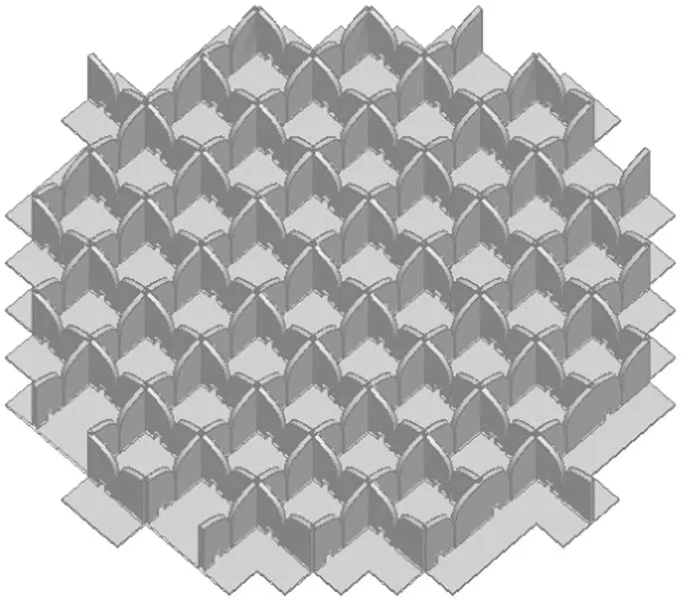
Figure 1.A square array of Vivaldi elements.There are 49 horizontal and 52 vertical elements,which correspond to two orthogonal linear polarizations.The distance between adjacent elements is 125 mm.
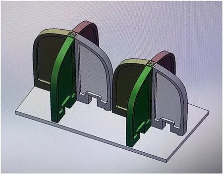
Figure 2.An all-metal Vivaldi feeding element.The slide-in-groove interlocking mechanism is clearly seen at the joining position of the ridges.

Figure 3.The 3D model of an all-metal Vivaldi feeding element.The labels illustrate the various parts of the element.The element is excited by the coaxial port at its bottom.
The 3D model of the Vivaldi element is shown in Figure 3.The only excitation is at the coaxial port at the bottom.The thickness and the profile of the ridge,width of the slot at various parts,the size of the resonant cavity and the position of the coaxial probe are adjusted to optimize the return loss of the coaxial port for the frequency range of 1.05–1.45 GHz.The ground plane is a square plate with a size of 125 mm.
The simulated return loss of a standalone single Vivaldi element is shown in Figure 4.The S11 is below −20 dB from 1.05 to 1.55 GHz,and below −15 dB from 1 to 1.65 GHz.The far-field pattern of this isolated vivaldi element is shown in Figure 5.The edge taper of this pattern w.r.t.the paraboloid part of FAST is only roughly −5 dB,which is certainly not good for a single feed receiver.The high edge taper of this small Vivaldi element is good for PAF,as can be inferred from the simulation results presented in Section 3.
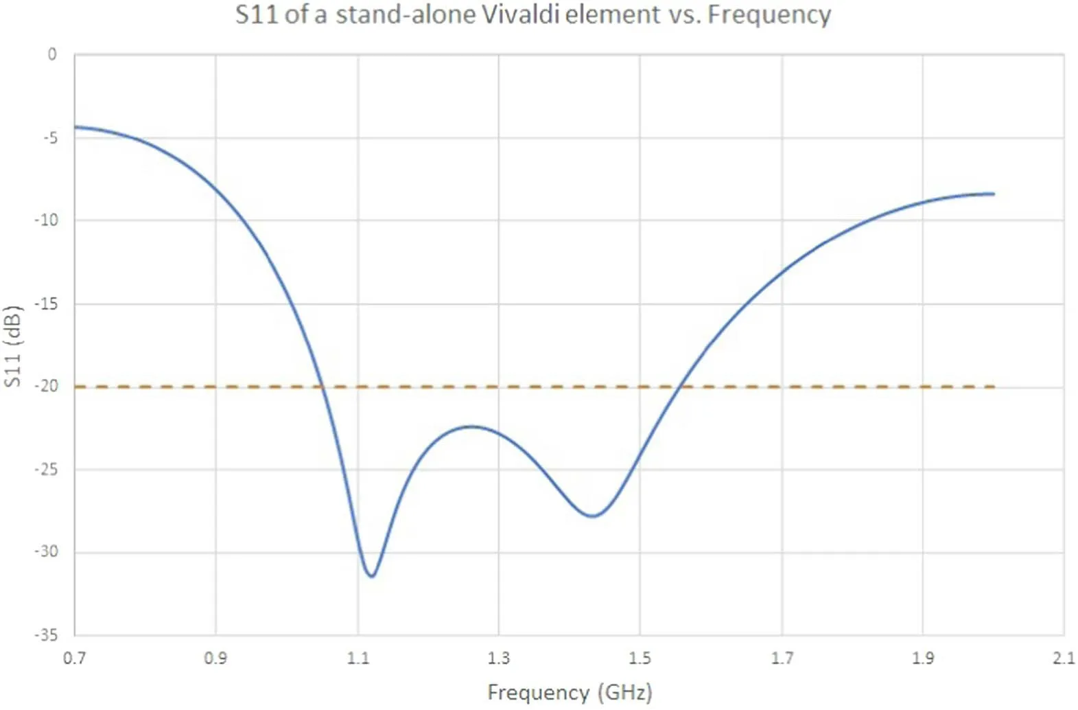
Figure 4.Simulated S11 of a standalone Vivaldi feeding element.The S11 is below −20 dB from 1.05 to 1.55 GHz,and below −15 dB from 1.0 to 1.65 GHz.The orange dashed line indicates a return loss of −20 dB.
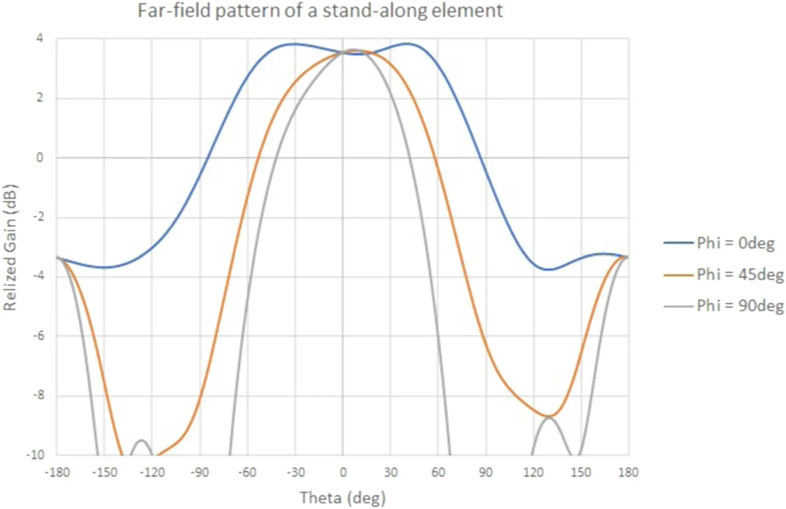
Figure 5.Far-field pattern of an isolated single Vivaldi element.The taper at 56°.4 is roughly from 4 to 5 dB.
Imagine a plane wave coming from direction of the optical axis of the paraboloid,it will be reflected by the paraboloid and form an Airy dot on the focal plane.In order to collect the reflected energy on the focal plane,the Vivaldi elements are interconnected to form an array to cover the Airy dot as much and as efficiently as possible.Since the elements are closely packed together,mutual coupling among them is inevitable.The return loss,far-field pattern of any Vivaldi elements in the array will then be different from that of a standalone element.
A full-wave electromagnetic (EM)simulation of the explicit array as shown in Figure 1 is done using the HFSS software package.Figure 6 shows the coupling level between the central and some of the other elements.At all frequencies,the level of mutual coupling becomes weaker as the distance between the elements increases.The S12,which is the level of the coupling between adjacent elements,decreases as the frequency increases.However,for element pairs with larger distances,the level of mutual coupling becomes larger as the frequency increases.For frequencies higher than 1.5 GHz,the level of mutual coupling does not change much as the distance increases.This may imply that the mutual coupling at higher frequencies is in different modes due to the size of the element relative to wavelength,and this may partly explain the gain reduction of the PAF combined with the main reflector of FAST at higher frequencies,as mentioned in Section 3.1.A PAF with smaller-sized elements would be required if operation at higher frequencies is desired.
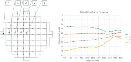
Figure 6.Simulated mutual coupling level between the central element and several other elements,as indicated in the left figure.The coupling normally becomes weaker as the distance between the elements gets larger as expected.
Figure 7 shows the simulated S11 of all the embedded elements in the array,together with the S11 of a standalone element.The return loss is a bit worse than a standalone element from 1.05 to 1.45 GHz,but is still below −10 dB.One remarkable phenomenon is that the S11 for frequencies below 1 GHz becomes better because of mutual coupling.This may enable the PAF receiver to operate over a wider frequency range than a standalone element.The simulated gain of the PAF combined with the main reflector of FAST presented in Section 3.1 also illustrates the wideband feature of the PAF.
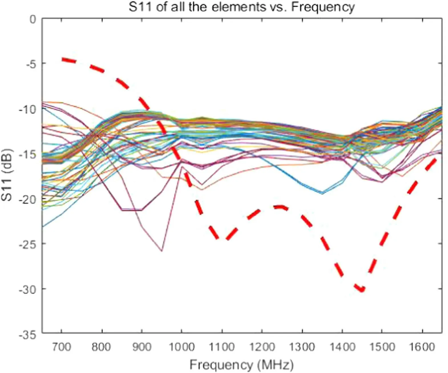
Figure 7.Simulated S11 of all the embedded elements in the PAF array and a standalone element(red dashed line).The S11 of embedded elements are below −10 dB for frequency range of 1.0–1.6 GHz,but lower down to −15 dB at 650 MHz.This is due to mutual coupling effect among the elements and enables the PAF to operate over a wider frequency range than a standalone element.
The far-field patterns of the embedded elements are also different compared with a standalone element due to mutual coupling among them.Depending on the position within the array,the far-field patterns of the elements are not the same.Figure 8 shows the far-field patterns of two elements in the PAF array.The left figure is for the element on the edge.Compared with the far-field pattern of the element at the center of the PAF,the far-field pattern of the element at the edge has a somewhat wider beamwidth and a lower peak gain.The element at the edge will only be affected by the elements on one side of it and thus will be affected less than the central element which is surrounded by elements around it.
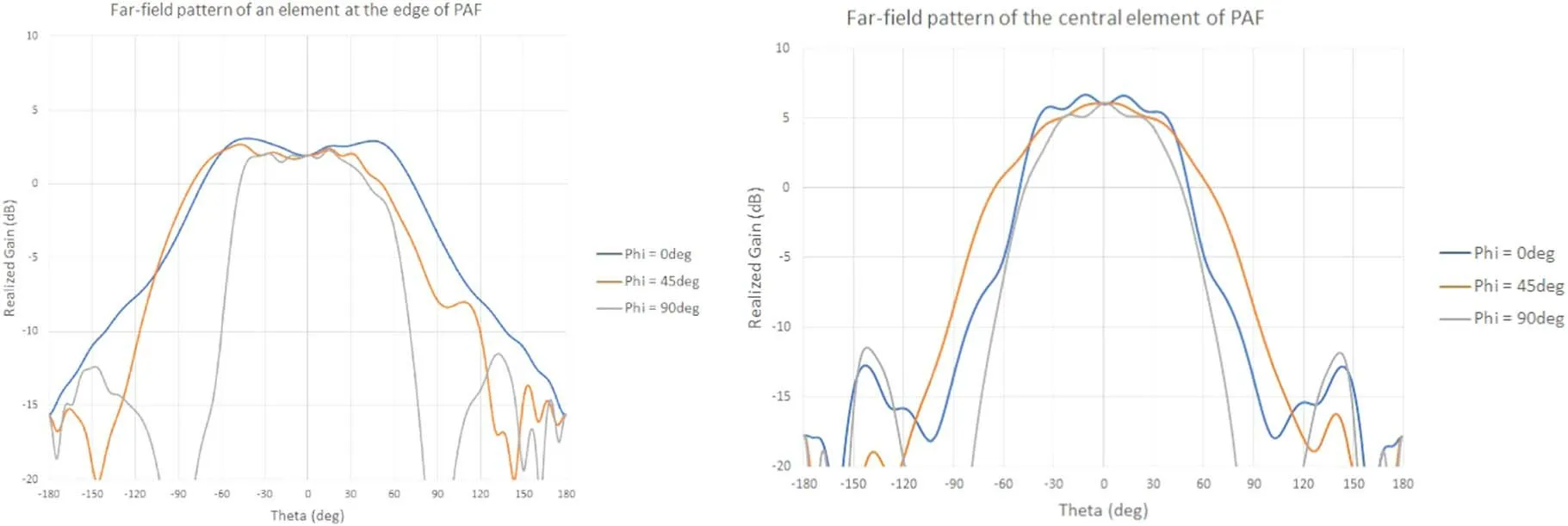
Figure 8.Simulated far-field pattern of two elements in the PAF array.The left figure is for one element at the edge of the array,while the right is for the central element.The far-field pattern of the central element shows a narrower beam and a higher on-axis gain.This is due to a stronger coupling effect for the central element.
This mutual coupling effect will affect the noise matching between the feeding element and the low noise amplifier(LNA),since the noise of the LNA that goes into the feed will partly be coupled into other feeding elements and will go into the beam-forming calculation eventually.Compared with a standalone feed receiver,this additional noise would require co-design of the LNA with the PAF array with a beam-forming algorithm.This effect is usually referred to as active impedance matching.
3.Simulation of the PAF Combined with the Main Reflector of FAST
A simulation of the efficiency (gain) and system noise temperature of the PAF combined with the main reflector of FAST is presented in this section.The main reflector is modeled by discrete points separated by approximately 5 m.The PAF array is put at the focal plane,approximately 162.12 m below the center of the neutral spherical surface.
Considering an incoming plane wave,the response of each element is calculated following the reciprocity principle(Warnick et al.2018).First,the far-field pattern of one element of the PAF combined with the main reflector of FAST is calculated using the GRASP software package.The embedded far-field pattern of the element is taken as the input.The complex voltage of the far-field pattern at a certain direction is then taken as the response of this element,assuming that an incoming plane wave is coming from that particular direction.The effective area of this element combined with the main reflector can be estimated by using Equation (1).
In Equation(1),the Gain corresponds to the far-field pattern at a certain direction of the embedded element combined with the main reflector of FAST.
By repeating the above procedure for all the elements,the complex voltage received by each embedded element can be obtained.Notice that the mutual coupling effect among the feeding element is already taken into account because the embedded far-field pattern of each element is used.
Each feeding element is followed by an LNA,a banddefining filter and an RF circuit.The amplified complex voltages from all the elements are then weighted and summed to form a beam.The weighting factors will affect the gain and system noise temperature of the formed beam.
3.1.Gain or Effective Collecting Area
Assuming that the noise of the LNAs following each element are uncorrelated and the mutual coupling among the feeding elements are ignored,the conjugate field matching (CFM)beam-forming mode would provide the highest signal-to-noise ratio (SNR).Though the mutual coupling among the feeding element mentioned in Section 2 would induce the active impedance matching between the feeding elements and the LNAs,this will normally make the receiver noise a bit higher.Thus,the CFM beam-forming mode may not be exact for the highest SNR.The CFM beam-forming will still provide an idea of how much gain could be achieved.In the practical design of a PAF,the mutual coupling among the feeding elements and the beam-forming algorithm may need to be taken into account when designing the matching between the feeding element and the LNA.In the following simulation,the CFM beam-forming mode will be adopted.
The efficiency relative to a 300 m aperture of the CFM formed beam when pointing to the zenith of one linear polarization at several frequencies is shown in Figure 9.The efficiency of the other orthogonal linear polarization presents similar efficiency.The efficiency is about 0.63 at 1400 MHz and decreases to 0.53 at 950 MHz.However,the gain remains greater than 0.52 down to 650 MHz.At all frequencies,the gain remains almost constant up to an off-axis angle of 0°.06.The efficiency starts to decrease to 0.49 at 1500 MHz and 0.38 at 1650 MHz.
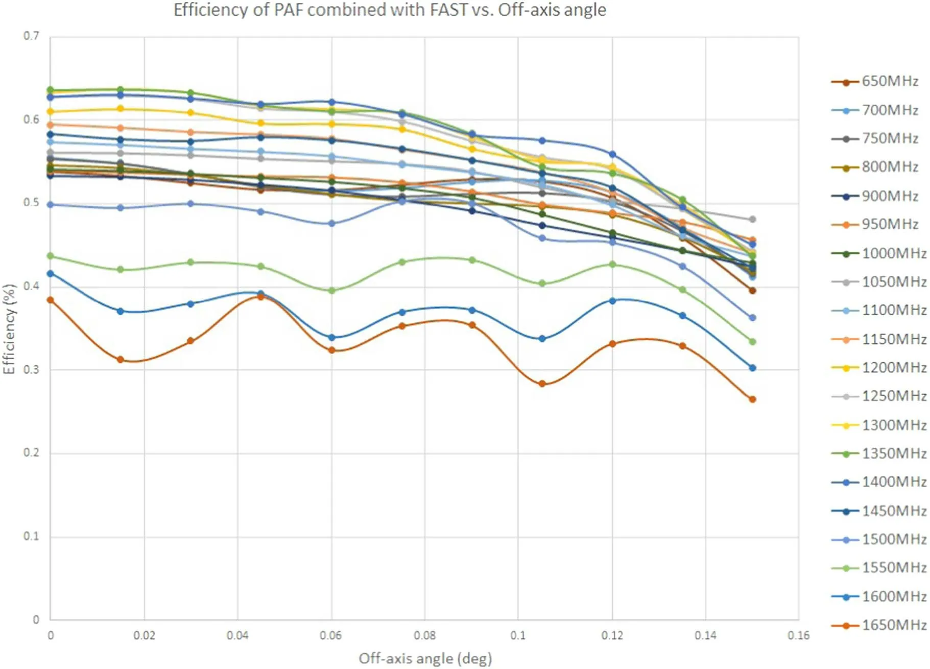
Figure 9.Simulated efficiency relative to a 300 m aperture at several RF frequencies of one polarization when the telescope is pointing to the zenith.The abscissa is the off-axis angle,which corresponds to the off-axis direction of incoming plane wave.The efficiency for all frequencies remains unchanged up to an off-axis angle of 0.06 and starts to decrease.This is mainly due to the limited size of this PAF prototype.
3.2.System Noise Temperature
In the CFM beam-forming mode,the voltages that come from each feeding element are weighted by the conjugate of the complex voltages received by each feeding element if a point source is put at a certain direction within the FoV.Under this weighting scheme,the PAF array itself could be thought of as a feed,and the far-field pattern of this feed could be obtained by the weighted sum of the far-field pattern of each element,taking into account of the different position of each feeding element on the focal plane.
Figure 10 shows two slices of the far-field patterns of the PAF under CFM beam forming at 1400 MHz when pointing at zenith angles of 0°and 40°.The slices are cut through the plane formed by the optical axis of the paraboloid at zenith angles of 0° and 40°.Clearly,the beams have a sharp cutoff at the edge of the paraboloidal part of the main reflector.This is mainly because the PAF has covered most of the Airy dot on the focal plane,while the traditional feed normally only receives the main lobe of the Airy dot.The antenna temperature is then obtained by integrating this pattern over the whole space,weighted by the radiation temperature of the environment.The sky and the reflector is set to be 5 K at L band,and the ground and mountain is set to be 300 K.The T-antenna is roughly 5–7 K when the antenna is pointing at the zenith.Assuming the receiver temperature to be 10 K,the Tsyswould then be 15–17 K.
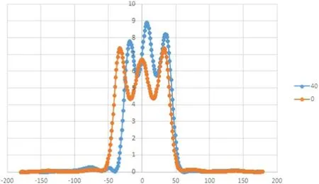
Figure 10.Far-field pattern of the PAF under CFM beam-forming mode.
In Figure 10,the left part of the blue curve(40°zenith angle)shows similar sharp cutoff compared with the orange curve(0°zenith angle),but shrinks inwardly by a certain amount.This is because the paraboloid is truncated by the ring girder of the main reflector.Compared with a traditional horn feed,this reduces the spillover dramatically.The calculated T-antenna at 40° zenith angle is almost the same as that when the zenith angle is 0°.Thus,the system noise temperature changes very little for zenith angles from 0°to 40°.In the case of a traditional horn feed,the Tsysmay go up to more than 40 K at a zenith angle of 40° and the gain may decrease by nearly 30%.If the PAF prototype presented in this paper is used,the gain may decrease by 20% at a zenith angle of 40°,but the Tsysalmost remains the same as that at a zenith angle of 0°.Thus,the adoption of the PAF may help to obtain higher sensitivity at large zenith angles for FAST.
3.3.Far-field Pattern of the Formed Beam
Under a certain weighting scheme,the PAF combined with the reflector will have different response to the incoming plane waves from various directions,which naturally forms a far-field pattern of the combination of the PAF and the main reflector.Under a CFM weighting scheme,the weighting factor to each element happens to be the conjugate of the received complex voltage for an incoming plane wave from a certain direction.The response of all the feeding elements of the PAF is calculated following the method mentioned in the beginning of this section.Applying the weighting factors to the response of all the feeding elements for incoming plane waves from different directions,a far-field pattern of the combination of the PAF and the main reflector of the antenna would then be obtained.
Figure 11 shows the far-field pattern of the PAF combined with the main reflector of FAST.The overlap of the adjacent beams is approximately at 3 dB,thus enabling continuous sky coverage,which could not be achieved by using multihorn feed array.The far-field patterns of small off-axis angles remains to be symmetric for the near-side lobes.This is mainly because the PAF would cover most of the Airy dot for small off-axis angles,thus the PAF will not suffer from the coma effect that the traditional horn feed often encounters.

Figure 11.Far-field pattern of the PAF combined with the main reflector of FAST.The adjacent beams overlap at approximately 3 dB to allow for a continuous sky coverage.
By a finer adjustment of the phase and amplitude of the weighting factor,more closely packed beams could be formed simultaneously,as shown in Figure 12.When observing a compact source with a radio telescope with larger aperture and when the antenna pointing is not perfect,these simultaneous closely packed multiple beams could be adopted to emulate a mechanical scan to calibrate the pointing of the antenna.This electrical pointing mode could make the pointing calibration much faster and could readily be realized by using a PAF receiver.
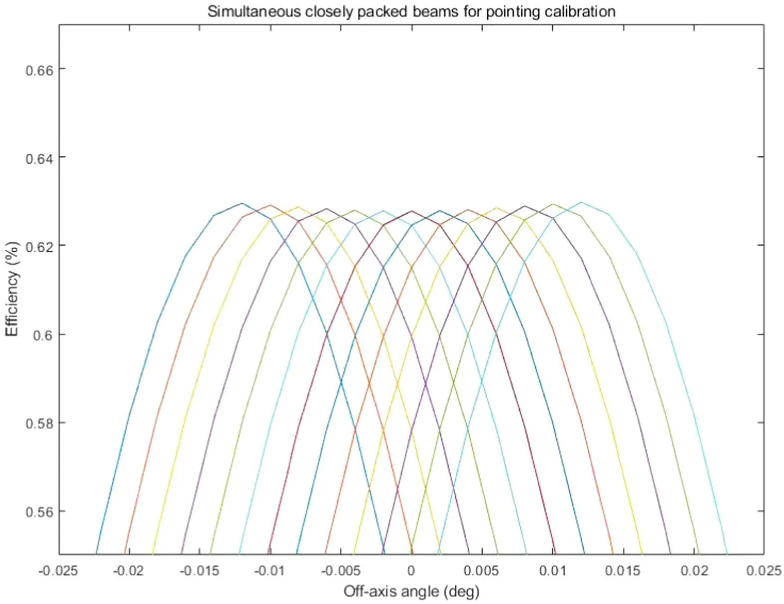
Figure 12.The simultaneously formed closely packed multiple beams.The peak gain of these beams are nearly the same.These beams could be used to realize electrical pointing for a large aperture antenna.
4.Measurement of a Single Element and the Manufacture of the Array
One single element is manufactured according to the simulation model.The feed is made of bare aluminium and no special coating is used.Figure 13 shows a photo of the manufactured single element.The inner conductor of the N-type connector is silver plated with a thickness of three times the skin depth and coated with a thin layer of gold with 0.05 um thickness to avoid oxidation.

Figure 13.The manufactured single element with a ground plane and an N-type connector.The element is fed by the coaxial port from the bottom.
The PAF array is made by interconnecting the individual Vivaldi elements to form a square array.The interconnection is realized by a sliding-in-groove mechanism,as shown in Figure 14.The S-parameter is affected by the addition of the ridges that belongs to other Vivaldi elements in the array,as can be seen from Figure 15.The mutual coupling among the closely packed elements improves the performance of the Vivaldi elements at lower frequencies,thus allowing the PAF array to operate over a wider frequency range compared with a standalone single Vivaldi element.
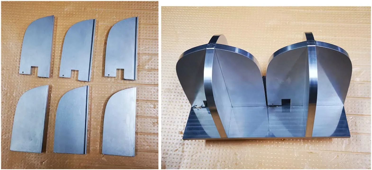
Figure 14.The ridges of the Vivaldi elements (left).The single feeding element with the ridges belongs to adjacent installed elements (right).
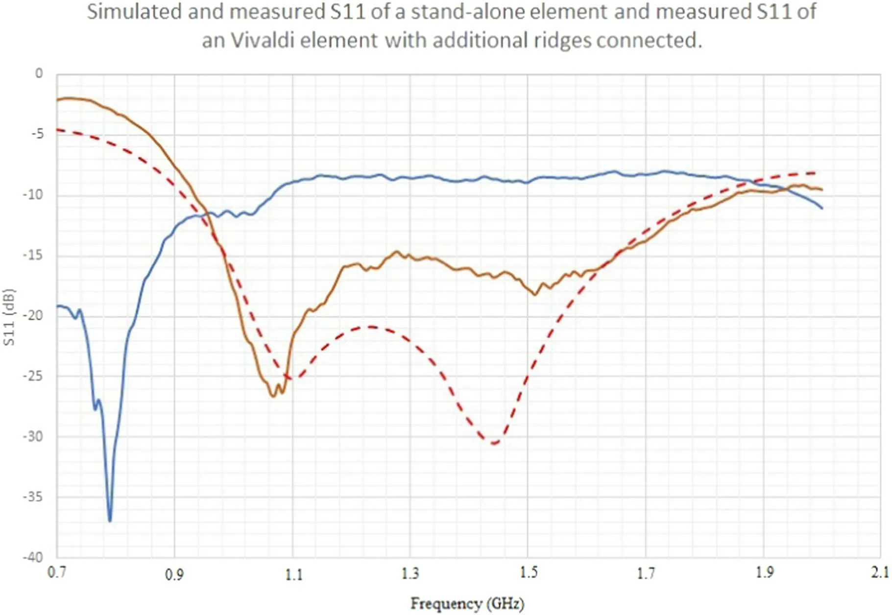
Figure 15.The measured S11 of the single element(brown curve)and with the added ridges that belongs to adjacent elements(blue curve).The red dashed line is for the simulated standalone single element.
5.Conclusion
A 40-element dual-polarization prototype PAF feeding array is introduced in this paper.EM simulation results manifest the mutual coupling among the closely packed feeding elements.The simulated performance of the combination of the PAF receiver and FAST’s main reflector indicates an efficiency of 62% at a zenith angle of 0° and a system noise temperature of 15–17 K.At zenith angles higher than 26°.4,although the actively formed paraboloid is truncated by the edge of the main reflector,the spillover is still small due to the fact that the PAF covers both the main and side lobes of the airy dot on the focal plane.Compared with the current multi-horn 19 beam receiver,the far-field patterns of PAF combined with FAST’s main reflector show better symmetry for off-axis beams and the PAF may enlarge the frequency coverage.The PAF may enable continuous sky coverage within the FoV.A manufactured single Vivaldi element confirms the simulation result and demonstrates the mutual coupling effect by adding several ridges that belong to adjacent elements.
Acknowledgments
This work is supported by the National Key R&D Program of China under grant No.2018YFA0404703,and the Open Project Program of the CAS Key Laboratory of FAST,NAOC,Chinese Academy of Sciences.We acknowledge the CASMPG LEGACY funding “Low Frequency Gravitational Wave Astronomy and Gravitational Physics in Space”.The authors thank Prof.Sander Weinreb for valuable discussions.
 Research in Astronomy and Astrophysics2023年8期
- Research in Astronomy and Astrophysics的其它文章
- Preliminary Exploration of Areal Density of Angular Momentum for Spiral Galaxies
- A Pre-explosion Effervescent Zone for the Circumstellar Material in SN 2023ixf
- Type Ia Supernova Explosions in Binary Systems: A Review
- Velocity Dispersion σaper Aperture Corrections as a Function of Galaxy Properties from Integral-field Stellar Kinematics of 10,000 MaNGA Galaxies
- A Catalog of Collected Debris Disks: Properties,Classifications and Correlations between Disks and Stars/Planets
- Decametric Solar Radio Spectrometer Based on 4-element Beamforming Array and Initial Observational Results
