低温辐射计光功率修正因子测试与分析
2023-08-21 07:34:32史学舜庄新港王国权刘红波张鹏举刘长明周金戈
光子学报 2023年7期
史学舜,庄新港,王国权,刘红波,张鹏举,刘长明,周金戈
(1 中国电子科技集团公司第四十一研究所,青岛 266555)
(2 国防科技工业光电子一级计量站,青岛 266555)
(3 电子测试技术重点实验室,青岛 266555)
0 Introduction
Optical radiation measurement generally refers to the use of basic measurement technology to establish a direct or indirect relationship between the measured optical radiation or radiometric parameters and the fundamental physical constants or physical quantities with low measurement uncertainty, so as to improve the reproduction or measurement level. During the development of basic optical radiation measurement technology,it has experienced radiation source standards represented by blackbody radiation source and synchrotron radiation source, and detector standards represented by absolute radiometer and self-calibration silicon photoelectric diode[1]. In the early 1980s, the development of cryogenic radiation technology greatly promoted the progress of absolute radiation technology and improved the measurement accuracy by an order of magnitude.In the optical comparison organized by the International Bureau of metrology, the consistency of the comparison results of cryogenic radiometers reaches 0.03%, which is the highest benchmark of optical radiation measurement in the world. As an important basis for optical radiation measurement, China has established optical measurement system based on cryogenic radiometer and has carried out measurement comparison of cryogenic radiometer[2]. Other values based on detector or radiation source are traced to cryogenic radiometer,or take cryogenic radiometer as circumstantial evidence to improve the measurement accuracy.
By introducing new technical means such as cryogenic, superconductivity and vacuum, the cryogenic radiometer uses the principle of electrical substitution measurement in the state of cryogenic superconductivity to trace the optical radiation measurement to the electrical parameter measurement that can be measured accurately, so as to realize the absolute measurement of radiant power. However, in the actual substitution process, in order to ensure the measurement accuracy, the factors affecting the equivalent substitution of photoelectric heating, such as window transmittance, stray light, and absorption ratio, need to be corrected.For example, with the help of standard whiteboard and integrating sphere, the Physikalisch-Technische Bundesantalt (PTB) measures the absorptivity of inclined bottom blackbody absorption cavity at 632.8 nm,which is 0.999 885[3]; the National Physical Laboratory (NPL) uses an intermediate through-hole four quadrant detector to test the stray light entering the cryogenic radiometer[4]; Changchun Institute of Optics, Fine Mechanics and Physics, CAS uses Monte Carlo fiber tracking to analyze the stray light characteristics of wide field of view absolute radiometer[5].
The above research only tests and simulates the factors affecting the equivalent substitution of photoelectric heating of cryogenic radiometer from a single aspect, and the technical means used have some defects. The 41st Research Institute of CETC takes the lead in developing the cryogenic radiometer for laboratory measurement[6]. In order to ensure the measurement uncertainty of the cryogenic radiometer, this paper introduces the optical path structure of the cryogenic radiometer test system, analyzes the substitution factors affecting the photoelectric heating and other effects of the cryogenic radiometer, and expounds the test simulation method for the correction factors of each influencing factor. Based on the finite element analysis method, the heat transfer model of absorbing cavity is constructed, and the photoelectric heating nonequivalence of cryogenic radiometer under different heating power is simulated and analyzed.
1 Cryogenic radiometer system device
Using the principle of equivalent substitution of photoelectric heating in cryogenic and vacuum environment, the cryogenic radiometer can realize the absolute measurement of radiant power. Taking the cryogenic radiometer as the primary standard and the laser as the light source, the responsivity of the standard transfer detector can be absolutely calibrated with the cryogenic radiometer, which can realize the transfer from the primary standard to the transfer standard. This calibration transfer method is widely adopted in the world[7-9].The laser source, transfer standard detector and cryogenic radiometer constitute the cryogenic radiometer test system, as shown in Fig. 1. In the laser source part, 632.8 nm laser is used as the initial light source, and then passes through optical elements such as polarizer, Laser Power Controller (LPC), spatial filter, collimating lens, LPC, mirror, shutter, aperture diaphragm. Finally, highly stable Gaussian laser output with vertical polarization is obtained. The emitted laser beam produces vertical polarized P light through the polarizer, and then the power stability is stabilized at 0.006% every 40 min with the laser power control facility. The spatial filter is used to filter out the high-order modes and stray light in the incident laser, and to acquire the basic mode Gauss light with the aperture, and then adjusts the collimated lens to converge the light beam into the absorbing cavity of the cryogenic radiometer.

Fig.1 System structure diagram of cryogenic radiometer device
After completing the laser beam modulation, referring to the indication of the four quadrant detector in the beam collimation system, the beam is incident to the center of the absorbing cavity through the Brewster window by adjusting the reflecting mirrors. The transfer standard detector adopts Si trap detector at the wavelength of 632.8 nm, and the switching between the transfer standard detector and the cryogenic radiometer in the optical path is realized with the help of a motorized translation stage.
Due to the introduction of cryogenic and vacuum technology, the measurement accuracy of the cryogenic radiometer has been greatly improved compared with the traditional radiometer. However, in the actual measurement process, when the incident light enters the blackbody cavity through the Brewster window, the absorption and reflection loss of the window, some stray light in the Gaussian beam , the absorptance of the cavity, the non-equivalence of photoelectric heating and conductor heat leakage will introduce measurement uncertainty; on the other hand, uncertainty will be introduced in the transmission process of the absorbing cavity and the trap detector due to the difference of the incident optical aperture and the different optical path.Therefore, it is necessary to correct the factors affecting the measurement uncertainty of cryogenic radiometer one by one. The correction formula is usually expressed as follows[10]
whereP0is the modulated measured laser power,Tis the transmittance correction factor of Brewster window,Sis stray light correction factor,Ais the blackbody cavity absorption correction factor,Nis the non-equivalent correction factor of photoelectric heating,Peis the electric power,Vhis the voltage at both ends of the blackbody cavity heating resistance, andVi、Riare the voltage and resistance value at both ends of the standard resistance in the electric heating circuit respectively.
2 Correction factor test device and method
2.1 Window transmittance
The undetermined incident laser is incident into the cryogenic radiometer at Brewster angle through Brewster window plate. For one thing, Brewster window can ensure 100% transmission of vertically polarized incident light in an ideal state, for the other it can effectively shield the stray light in the environment from entering the absorption cavity. However, in the actual optical path adjustment, affected by the adjustment accuracy, as well as the absorption, scattering and uniformity of the window itself, there are inevitable differences between the window transmittance and the theoretical value, and the transmittance in different experimental processes is affected by human factors, which is difficult to reproduce completely. Therefore, it is necessary to test the window transmittance online during each experiment.
In the measurement facility as shown in Fig.2, a beam alignment and test chamber is developed for window transmittance test. After completing a cryogenic radiometer optical power measurement, closing the vacuum valve between the cryogenic radiometer and the test chamber, the vacuum blind plate at the front end of the offaxis parabolic mirror is open to restore the Brewster window and the test chamber to a non-vacuum state,followed by testing the optical power values at the front end and rear end of the Brewster window with the Si detector and two-dimensional electric translation table. The power values noted asP1andP2respectively. The ratio ofP2andP1is the window transmittance correction factorT.
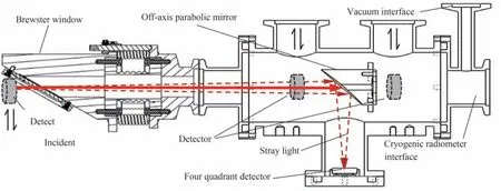
Fig.2 Schematic diagram of window transmittance and stray light measurement
2.2 Stray light
As shown in Fig. 2, the Gaussian incident laser beam enters the absorbing cavity of the cryogenic radiometer after passing through the Brewster window and the middle through-hole off-axis parabolic mirror in turn. The diameter of the off-axis parabolic mirror is 1 inch and the diameter of the middle through hole is 7 mm(the diameter of the blackbody cavity is 10 mm). Although several apertures are set in the incident light path,there are still some scattered light outside a certain range of the main beam that cannot enter the absorption cavity through the off-axis parabolic mirror through hole. This part of the scattered light cannot enter the absorption cavity and is regarded as stray light. Fig.3 shows the energy distribution of Gaussian beam in the cryogenic radiometer test system measured experimentally. The horizontal axis is the spot diameter and the vertical axis is the spot energy proportion. When the spot diameter is greater than 5 mm, the laser energy proportion has exceeded 99.9%. The beam alignment device judges and adjusts the orientation of the incident beam by monitoring the position of the stray light focus on the four quadrant detector, as shown by the dotted line light in Fig. 2.

Fig.3 Energy distribution of Gaussian beam
The transmittance of the incident Gaussian beam passing through the through hole of the parabolic mirror exceeds 99.9%, and the stray light intensity is very weak. The direct test accuracy of the four quadrant detector is poor, and some stray light is not converged to the four quadrant detector through the mirror. In this paper,with the test chamber shown in Fig. 2, the stray light radiation is indirectly calculated by testing the transmittance of the incident light through the off-axis parabolic mirror, which is similar to the transmittance test of the Brewster window. The ratio of the power of the front and the rear of the parabolic mirror is the stray light correction factor. Because through hole diameter of the parabolic mirror is smaller than the blackbody cavity diameter, all the light that does not pass through the through hole is regarded as stray light, and all the light that passes through the through hole will enter the absorption cavity.
2.3 Absorption of blackbody cavity
As the core light radiation receiving device of the cryogenic radiometer, the fundamental purpose of the absorbing cavity is to form a light trap so that the light radiation incident into the cavity is approximately completely absorbed after multiple reflections[11]. On one hand, we need to develop a blackbody cavity with ultra-high absorptance. The absorptance of the cavity is related to its structure, shape, length and the characteristics of the blackened material; on the other hand, it is necessary to accurately measure the absorptivity of the cavity for the later photoelectric heating equivalent correction of the cryogenic radiometer. In our previous research work, Monte Carlo ray tracing method is used to analyze the factors affecting the cavity absorptance. Reference[12]specifically introduced the facility and method of measuring the cavity absorptance by substitution method.
2.4 Light and electric heating non-equivalence corrections
The main source of the non-equivalence of photoelectric heating is the difference between different heating areas and heating positions during photoelectric heating, which makes the photoelectric heating power required by the temperature sensor to obtain the same temperature rise different. Fig.4 shows the schematic diagram of photoelectric heating non-equivalence of blackbody cavity, which indicates the photoelectric heating position,heating area and detector position. Although the absorbing cavity is made of oxygen free copper with low heat capacity and high thermal conductivity, so that the cavity can quickly reach thermal balance, there will still be a small temperature gradient difference in the temperature distribution of the cavity during thermal balance, and the gradient difference is slightly different due to different photoelectric heating paths.

Fig.4 Schematic diagram of photoelectric heating non-equivalence
It is difficult to directly measure the photoelectric heating non-equivalence correction coefficient through experiments. Only the approximate value of non-equivalence can be given, and the temperature distribution and non-equivalence of optical heating and electric heating cannot be measured quantitatively[13]. Finite element analysis method is widely used in the world to simulate the steady-state response and evaluate the transient response of cryogenic radiometer. With its flexibility and effectiveness, finite element analysis method has become the most effective method to deal with complex models[14].
3 Test results and analysis
3.1 Transmittance and stray light
According to Fig. 3, the energy spatial distribution of the incident laser beam in the cryogenic radiometer test optical system after spatial filtering is Gaussian distribution, and more than 99.9% of the energy is concentrated in a circular area with a diameter of 5 mm. In order to maximize the incident light entering the black body cavity of the cryogenic radiometer through the parabolic mirror and reduce the stray light and photoelectric non-equivalence, the diameter of the parabolic mirror is designed to be 25.4 mm, the diameter of the middle through hole is 5 mm and the focal length is 50.8 mm. Fig.5 shows the assembled Brewster window and the beam alignment and test device composed of parabolic mirror, four quadrant detector and beam alignment and test chamber. The incident light enters the blackbody cavity through the Brewster window through the off-axis parabolic mirror, and the direction of the incident light is adjusted with reference to the indication of the four quadrant detector until the indication of the four quadrants of the four quadrant detector is the same, indicating that the incident light enters the center at the bottom of the blackbody cavity. Fig.5 shows the stray light spot shape of the adjusted incident light reflected by the off-axis parabolic mirror, and the incident light power is stable at 500 μW, where Fig. 5(a) shows the stray light spot at 12.7 mm from the parabolic mirror through hole in the light on environment, and Fig.5 (b)~(d) shows the stray light spot at 12.7 mm, 25 mm and 50.8 mm(focus) from the parabolic mirror through hole in the darkroom environment, it can be clearly seen that the stray light that fails to enter the cryogenic radiometer through the parabolic mirror and the convergence of the light spot reflected by the mirror.

Fig.5 Stray light spot shape at various distance and lighting conditions
During the process, Si photodetector, preamplifier, digital voltmeter and two-dimensional electronic control translation table are used to build Brewster window transmittance and stray light detection devices.The optical power values at the front and back ends of Brewster window areP1=624.302 μW andP2=622.315 μW. Incident light power at the rear end of parabolic mirrorP3=621.701 μW. Therefore, the transmittance of Brewster window is 0.996 817 and the stray light is 0.614 μW. Stray light correction factor 0.999 013.
3.2 Absorptivity
The absorptivity of black body cavity is related to many factors, such as cavity structure, cavity aspect ratio, absorptivity characteristics of blackened materials, incident light position and angle, etc. The experiment uses the comparison method to test the absorptivity of the blackbody cavity with the help of the low split ball.The simulation and test of the absorptivity characteristics of the blackbody cavity have been completed in Refs.[11]and [12]. The experimentally measured absorptivity of the blackbody cavity at 632.8 nm is 0.999 95.
3.3 Photoelectric heating non-equivalence
In the experiment, SolidWorks simulation software is used to analyze the thermodynamic characteristics of the blackbody cavity assembly of cryogenic radiometer. Firstly, the three-dimensional mathematical model of blackbody cavity assembly is constructed by SolidWorks, and the thermodynamic characteristic parameters of materials at temperature of 6.5 K are added, and then the established mathematical model is imported into SolidWorks simulation for thermodynamic simulation. As shown in Fig. 6, heating power, between 100 μW to 1 mW, stepped 100 μW, is applied to the light heating area and the electric heating area, respectively. The temperature at the heat sink position is set to 6.5 K. Since the single absorption rate of the black body cavity blackened material at 632.8 nm is about 92%, and the light energy is basically absorbed after two reflections, in the simulation process, only the light heating power is applied in the first two reflection areas, and the heating power at the primary reflection position is set to 92% of the total power, and the heating power at the secondary reflection position is set to 8% of the total power. After the heating power is applied, the grid is divided and the finite element heat transfer system analysis model is established. The model is composed of 59 424 nodes and 34 081 elements.
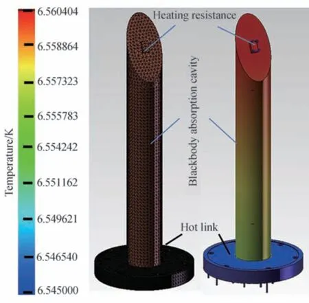
Fig.6 1 mW heating power temperature gradient diagram
After completing the above steps, it will start to solve the finite element analysis model. Fig. 7 shows the temperature gradient distribution of the cavity under 1 mW heating power, and the temperature difference at different cavity positions can be clearly seen. By reading the temperature at the center of the temperature sensor,the cavity temperature rises and non-equivalence factor of optical heating and electric heating under different heating power can be calculated, as shown in Table 1. The photoelectric nonequivalence correction factor under different heating power is between 1.009 213 and 1.009 246, and the difference is slight. It can be found that under the same boundary conditions of optical power and electric power, the temperature rise of optical heating is slightly higher than that of electric heating, mainly because the position of optical heating is closer to the temperature sensor. Through error analysis of the test results in Table 1, it can be obtained that the photoelectric non-equivalence factor of the cryogenic radiometer is 1.009 240 ± 0.000 010.
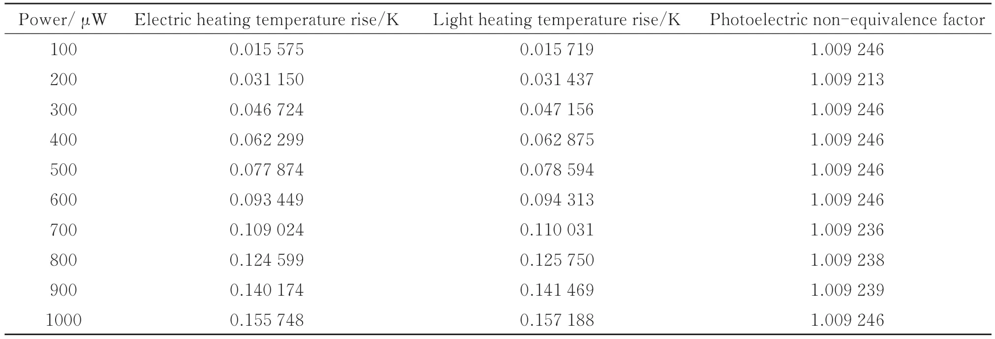
Table 1 Photoelectric heating non-equivalence factor under different heating power
4 Conclusion
The cryogenic radiometer adopts the principle of electric substitution measurement to realize the absolute measurement of optical power, and the measurement uncertainty reaches the order of 10−5. The accurate measurement of optical power is inseparable from the measurement of correction factors such as Brewster window transmittance, stray light, blackbody cavity absorptivity and photoelectric heating non-equivalence of cryogenic radiometer. Aiming at the transmittance and stray light correction factor of Brewster window, the self-designed beam alignment and test chamber are used for on-line measurement. At the same time, the Gaussian beam energy distribution after spatial filtering is analyzed. It is proposed to obtain the stray light distribution and energy by measuring the transmittance of incident light through off-axis parabolic mirror.Finally, the transmittance of Brewster window is 0.996 817, stray light correction factor 0.999 013. In addition,the spectral absorptivity of the black body cavity is analyzed and tested, and the factors affecting the absorptivity of the black body cavity are analyzed. The simulated and measured results are consistent. The absorptivity of the black body cavity at 632.8 nm is 0.999 950. Additionally, the heat transfer model of blackbody cavity is constructed by finite element analysis method, and the photoelectric heating non-equivalence of cryogenic radiometer under different heating power is simulated and analyzed. The simulation results show that the difference of photoelectric heating non-equivalence of cryogenic radiometer under different heating power is slight, and the photoelectric non-equivalence factor of the cryogenic radiometer is 1.009 240±0.000 010. The research results provide certain references for the optimization design and correction factor test of each functional module of cryogenic radiometer.
猜你喜欢
真空与低温(2021年6期)2021-12-02 09:19:50
真空与低温(2021年5期)2021-10-19 04:40:38
上海航天(2021年3期)2021-07-21 14:02:12
现代青年·精英版(2021年5期)2021-06-23 22:45:22
华人时刊(2020年21期)2021-01-14 01:33:30
金桥(2020年10期)2020-11-26 07:23:16
空间科学学报(2020年3期)2020-07-24 09:23:32
真空与低温(2019年5期)2019-10-18 09:08:30
成都信息工程大学学报(2018年1期)2018-05-31 08:40:27
知音海外版(上半月)(2018年5期)2018-05-23 03:11:20