
A stability locomotion-control strategy for quadruped robots with center-of-mass dynamic planning
2023-06-16 06:50:14YangyangHANGuopingLIUZhenyuLUHuaizhiZONGJunhuiZHANGFeifeiZHONGLiyuGAO
Yangyang HAN, Guoping LIU, Zhenyu LU, Huaizhi ZONG, Junhui ZHANG, Feifei ZHONG, Liyu GAO
Research Article
A stability locomotion-control strategy for quadruped robots with center-of-mass dynamic planning

1School of Advanced Manufacturing, Nanchang University, Nanchang 330031, China2State Key Laboratory of Fluid Power and Mechatronic Systems, Zhejiang University, Hangzhou 310058, China
Locomotion stability is essential for controlling quadruped robots and adapting them to unstructured terrain. We propose a control strategy with center-of-mass (CoM) dynamic planning for the stable locomotion of these robots. The motion trajectories of the swing legs are synchronized with the CoM of the robot. To implement the synchronous control scheme, we adjusted the swing legs to form a support triangle. The strategy is applicable to both static walk gait and dynamic trot gait. In the motion control processes of the robot legs, the distribution of the ground reaction forces is optimized to minimize joint torque and locomotion energy consumption. We also used an improved joint-torque controller with varied controller coefficients in the stance and swing phases. The simulation and experimental results demonstrate that the robot can complete omnidirectional locomotion in both walk and trot gaits. At a given locomotion speed, the stability margins for the robot during walking and trotting were 27.25% and 37.25% higher, respectively, than in the scheme without CoM planning. The control strategy with energy consumption optimization (ECO) reduced the energy consumption of the robot in walk and trot gaits by 11.25% and 13.83%, respectively, from those of the control scheme without ECO.
Center-of-mass (CoM) planning; Quadruped robot; Cooperative scheme; Ground reaction forces; Stability margin
1 Introduction
Quadruped robots have been extensively resear ched owing to their extreme mobility and adaptability to different terrains; for example, the well-known ANYmal (Hutter et al., 2016, 2017), HyQ (Focchi et al., 2017; Gonzalez et al., 2020), and MIT Cheetah series (Hyun et al., 2014; Park et al., 2017). Stability is the basis for quadruped robots to locomote over complex terrain environments. Inspired by the rhythmic movement of organisms, some researchers have introduced locomotion control with a central pattern generator (CPG) to increase the stability of quadruped robots. Shao et al. (2022) proposed a new control framework based on CPG phase guidance, which can generate various gaits and realize transition between different gaits. Zhang Y et al. (2021) proposed a dynamics-based CPG network control system and simulated the trot gait of a quadruped robot. Fukui et al. (2019) demonstrated that a CPG network with vestibular feedback was an effective and practical gait generator that enabled autonomous gait transitions. Liu and Zhang (2020) established a van der Pol CPG network for a quadruped robot with four primary gaits. They analyzed the existing conditions of model bifurcation and the coupling strength range between the oscillators. However, modulating various CPG models for robot position control is a complex and cumbersome task because the model parameters usually have no apparent physical meaning.
Other researchers have focused on gait planning to improve the stability of robots. In a comparison study of several stable static gaits, Hao et al. (2020) identified the static gait that maximized the stability margin. Wang et al. (2020) attempted to improve the walking velocity of quadruped robots with static gaits. They proposed two methods for walking on an assumed set of irregular footholds. Yeom and Bae (2021) proposed a gait-stabilization algorithm that adjusts the contact time between the robot legs and the ground. They demonstrated the stability of their algorithm by using a Lyapunov function. Chignoli and Wensing (2020) presented a control strategy for quadruped balancing that enabled postural stability in underactuated contact configurations. Zhang et al. (2019) proposed a continuous static gait planning method for robots walking blindly over unknown rough terrain. McClain and Meek (2018) selected an appropriate gait for a quadruped robot assisting human walking by estimating the optimal parameters of stable static gaits. However, locomotion stability of robots has been much more extensively researched for static than for dynamic gaits. In our proposed stability-control strategy, control of static gaits is extended to control of dynamic gaits, thereby expanding the application scope of the stability-margin method.
Some researchers have applied optimization algorithms for torque control of quadruped robots. Using a Hermite interpolation method, Tian et al. (2019) generated a smooth gait under boundary constraints, and established a control framework for quadruped robots based on virtual model control. Zhang ML et al. (2021) proposed a double-layer back-propagation neural network that learns the parameter rules of a proportional-integral-derivative controller. This method avoids the inconvenient adjustment of artificial parameters otherwise necessary for the hydraulic drive unit of a legged robot. di Carlo et al. (2018) converted dynamics locomotion control into a convex optimization problem based on a simplified model. They determined the ground reaction forces (GRFs) for a quadruped robot using model predictive control (MPC). Dudzik et al. (2020) combined regular predictive control and whole-body impulse control into an integrated system for small robots. Several groups have tried various algorithms to optimize function. Pepe et al. (2021) determined the optimal trajectory of a quadruped robot using a genetic algorithm that seeks the optimal gait sequence at different velocities. Srinivas et al. (2021) optimized the joint positions of a robot with eight degrees of freedom (DoFs) using the particle-swarm optimization algorithm. Lee and An (2021) proposed a self-balancing control algorithm for quadruped robots, based on reinforcement learning and an artificial neural network, which replaces the analysis-based control algorithm. Arena et al. (2021) proposed a data-driven neural network based on nonlinear MPC, and compared the simulation results for nonlinear MPC with those for linear MPC. Ding et al. (2021) proposed a representation-free MPC framework that controls various locomotion patterns of robots in 3D space. However, the complex algorithm burdened the computing power of the robot, thereby increasing the difficulty of implementation and the investment cost. Our proposed control strategy, which involves GRF optimization based on MPC (di Carlo et al., 2018), designs the objective function to minimize GRFs and energy consumption and simplifies the optimization algorithm to reduce the amount of computation. Moreover, it has flexible weight coefficients, which allow for different stances and swing phases of the legs. We aim to show how this design reduces the complexity of the control system.
The main contributions of this study are summarized below.
(1) The center-of-mass (CoM) and swing legs of the robot are synchronized to optimize coordination during locomotion. The scheme allows real-time trajectory planning for the CoM, and the stability margin can be flexibly and conveniently adjusted to an appropriate value. The plan can be dynamically expanded to trot gait based on walk gait.
(2) Locomotion stability and energy consumption are simultaneously considered with a constant desired velocity. The stability goal is accomplished by real-time dynamic planning for the CoM. Energy consumption is minimized through the objective function of the quadratic planning of the GRFs. As the forces on the robot legs differ between the stance and swing phases, they are handled under different control strategies. The joint torques of the standing legs are primarily generated by mapping the optimal GRFs, whereas a joint proportional-derivative (PD) controller commands the swinging legs.
(3) The implementation of the designed control strategy of the robot was verified in various ways. Controller performance was demonstrated through simulations and experiments. The tracking errors of the base orientation were analyzed at different velocities. Taking the stability measurement criterion (Gonzalez de Santos et al., 1998) as the judgment measure, we compared the real-time stability margins of the control schemes with and without CoM planning in walk and trot gaits. We also compared the instantaneous power and mean GRFs (in thedirection) of the robot legs with the control strategies, both with and without energy consumption optimization (ECO), in the two gaits; we took the energy model used by Zhou et al. (2021) as the judgment measure.
The remainder of the paper is organized as follows. Section 2 introduces the robot model and the overall design framework of the controller. Section 3 describes each part of the controller and elaborates on the dynamic planning algorithm of the CoM and the principle of the state machine. Section 4 covers the simulation and experimental platforms and the parameter settings of the controller, as well as the simulation and experimental results. Section 5 concludes the study and discusses future work directions.
2 Robot model and control architecture
The employed robot models are shown in Fig. 1, and the physical parameters of the robot are shown in Table 1.
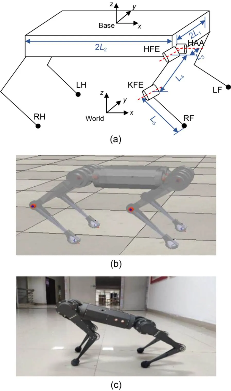
Fig. 1 Robot models: (a) simplified model and coordinate systems; (b) simulation model; (c) experimental prototype. LF, RF, RH, and LH represent four legs (L: left; R: right; F: front; H: hind). HAA: hip-abduction/adduction joint; HFE: hip-flexion/extension joint; KFE: knee-flexion/extension joint
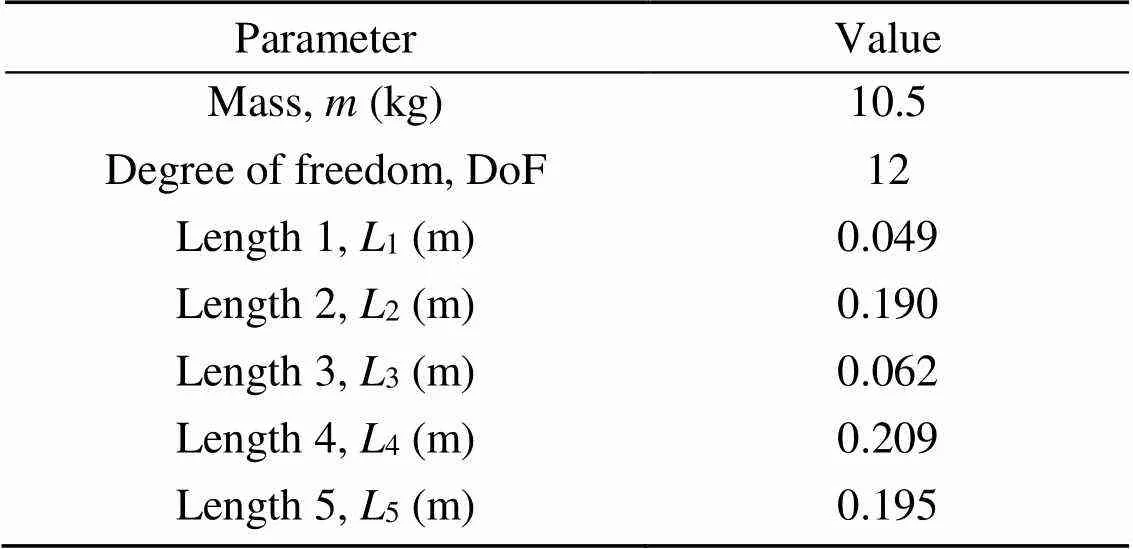
Table 1 Physical robot parameters

3 Locomotion-control strategy
First, we planned the gait and swing-leg trajectories. We then compared two coordination schemes when used for the CoM and legs, and designed an algorithm to implement the dynamic CoM planning. We will also present the state transition process.
3.1 Gait planning
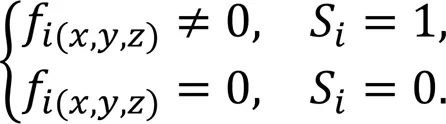
Each typical gait was assigned a corresponding gait pattern (Hyun et al., 2014). The gait sequence and phase relation of walking are shown in Figs. 3a and 3b, respectively. The swing sequence was LF-RH-RF-LH, and the phase () difference between adjacent swing legs was 0.25. The current stateSof theth leg was defined asS=0 during the swing phase andS=1 during the stance phase. The robot legs were periodically switched between the stance and swing phases depending on the gait type. The phase-control signal (time cycle=1 s) generated by the gait scheduler for walk gait is shown in Fig. 3c.
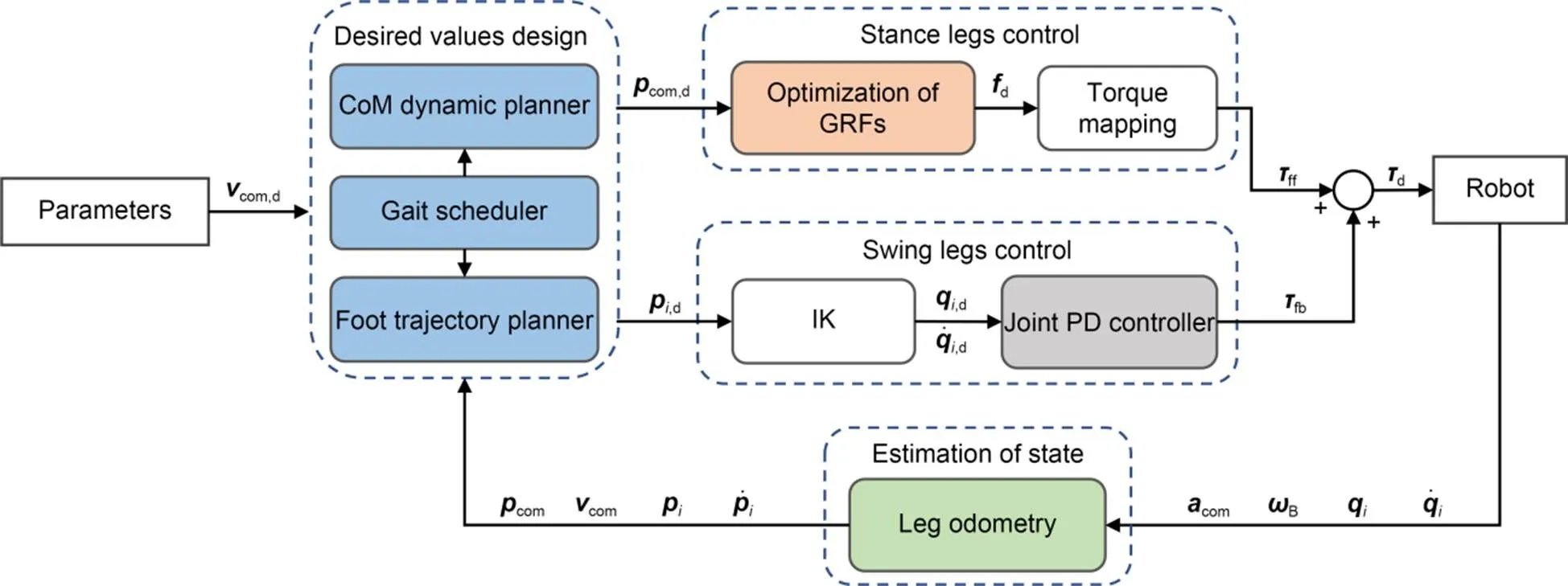
Fig. 2 Block diagram of the control system. vcom is the velocity of the CoM; pcom is the position of the CoM; pi is the footstep location
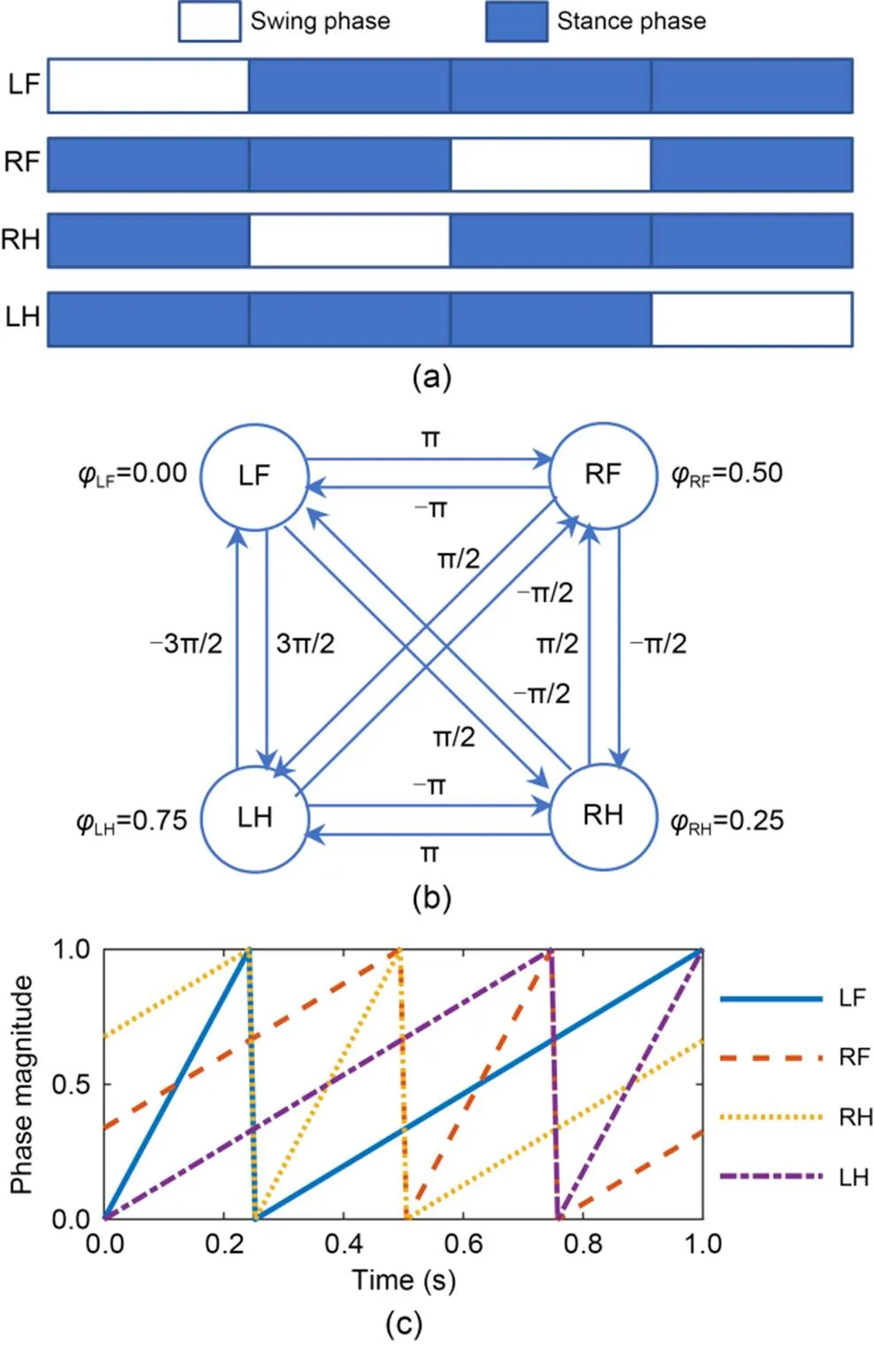
Fig. 3 Gait pattern for walk gait: (a) gait sequence; (b) phase relation; (c) phase-control signal
3.2 Swing-trajectory planning
The desired velocity of the robot is expressed as


The desired footstep locations of theth swing leg are given by


3.3 Dynamic planning for the CoM
The CoM was dynamically planned in order to enhance its locomotion stability. To coordinate the motions of the CoM with the swing, we first determined the cooperative scheme and then designed the motion trajectory of the CoM.
3.3.1Synchronous cooperation design
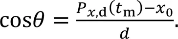
The support triangle, which was determined by the cooperative scheme between the motions of the CoM and swing legs, influenced the planning of the CoM and control strategy. The two cooperative schemes for walk gait are shown in Fig. 4. Figs. 4a and 4b show the asynchronous and synchronous cooperative schemes, respectively, and Figs. 4c and 4d show their corresponding CoM velocities (,d=0.2 cm/s).
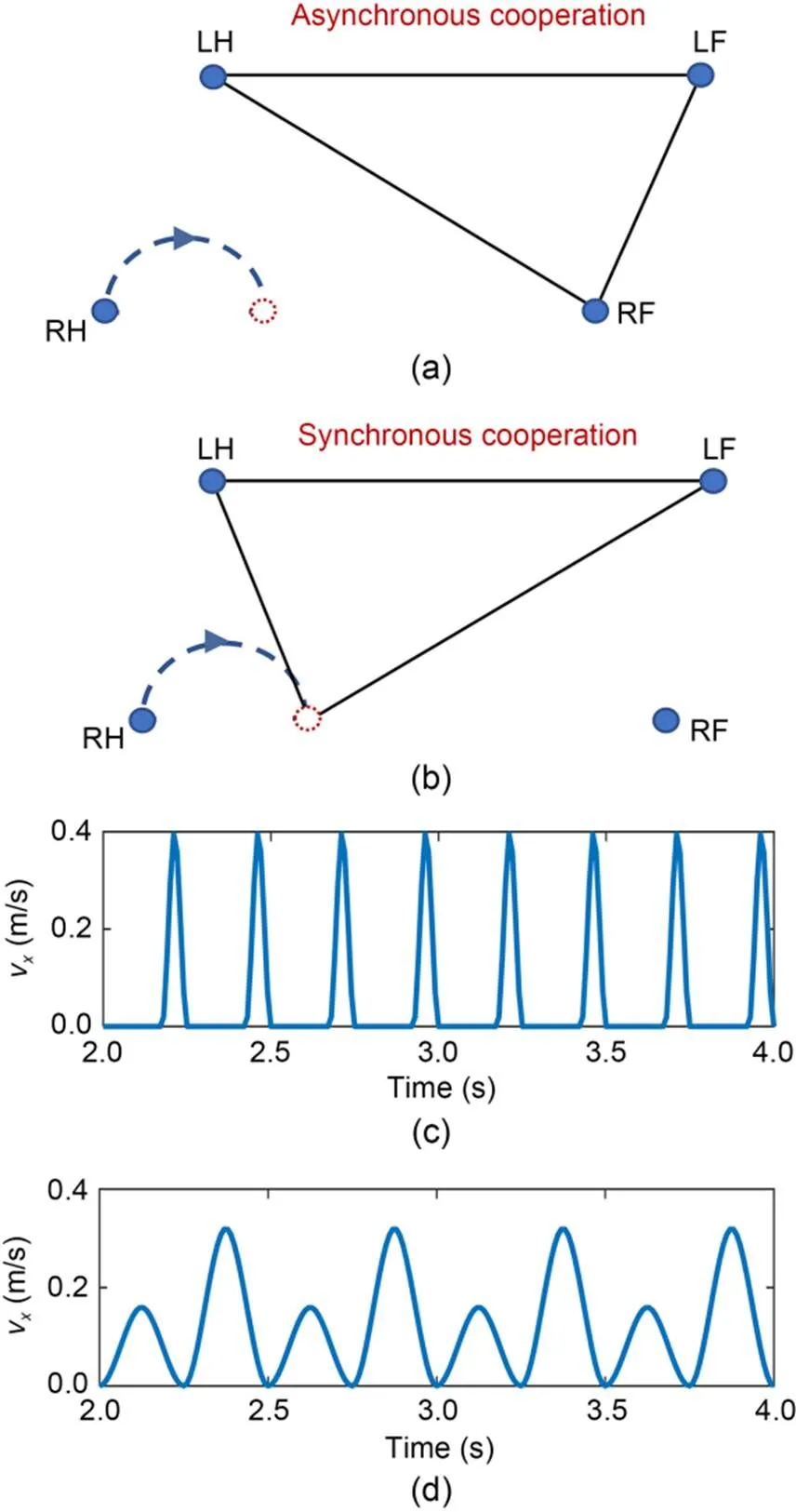
Fig. 4 Two cooperative schemes (walk gait): (a) asynchronous scheme; (b) synchronous scheme; (c) CoM velocity in the asynchronous scheme; (d) CoM velocity in the synchronous scheme. The solid circle represents the current stance position of each leg, the dotted circle represents the planned location of the swing leg, and the areas surrounded by solid black lines represent support triangles in Figs. 4a and 4b
The two schemes generated different support triangles for the same swing leg (RH). In the asynchronous scheme (Fig. 4a), the CoM and swing leg of the robot moved sequentially. Thethswing leg moved first, followed by the CoM. The next leg then swung in sequence. In this scheme, the three stance legs formed the support triangle, and the support vertices were the foot positions of the stance legs.
In contrast, the designed synchronous scheme led to simultaneous motions of the CoM and swing leg (Fig.4b). The next leg and the CoM then moved at the same time. In our scheme, the legs other than the next swing leg formed the support triangle. The swing leg became a support leg, and its vertex was the planned footstep location.
The CoM velocities were discontinuous and varied more widely in asynchronous than in synchronous cooperation (Fig. 4c). During the movement of the swing leg, the CoM was stationary, and its velocity was zero. When the CoM moved, its velocity quickly increased from zero to peak. In contrast, as our scheme synchronized the motions of the CoM and swing leg (Fig. 4d), the velocity was more continuous, smoother, and varied over a smaller range than the velocities obtained in the asynchronous scheme.
3.3.2Motion trajectory of the CoM design
The initial and target positions of the CoM projection are defined as,d(0) and,d(m), respectively, where0andmare the start and end times of the CoM planning, respectively. The positions of the three vertices1(1,1),2(2,2), and3(3,3) on the projection plane of the support triangle are depicted in Fig. 5a.
The stability margin, defining the distance from,d(m) to0(0,0) (Gonzalez de Santos et al., 1998), is calculated using Eq. (4).,d(m) can be adjusted by varying the parameterin the support-triangle plane. The inequation (5), which constrains the generated target position within the plane of the support triangle, must be satisfied.
Fig. 5 CoM planning and synchronous cooperative scheme in the projection plane: (a) CoM planning in the projection plane; (b) synchronous cooperation for walk gait; (c) synchronous cooperation for trot gait

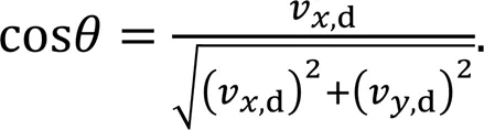
To reduce the movement range of the base on the-axis, we set the direction to be consistent with the locomotion direction of the robot:
A minimum-jerk quintic spline with a fourth-order continuous derivative was planned between the initial and target positions. The CoM velocities and accelerations were set to zero at the start and end times to ensure smooth movement of the CoM along the planned trajectory.
The designed scheme was appropriate for the walking gait, in which one leg swings at a time. Fig. 5b shows the cooperation between the CoM and swing legs of the robot in walking, along with the dynamic trajectory plan of the CoM. Also shown are the implementation details of the synchronous cooperative scheme based on the step sequence generated by the gait schedu ler. Note that the vertices of the support triangle are the stance positions in the next phase.
To extend the synchronous cooperative scheme to the trot gait, we took the positions of the stance legs as the two support vertices of the supportive triangle, and the third support vertex employed the planned footstep location of the forward swing leg. Fig.5c shows the support triangle formed by these vertices and the implementation details of the synchronous cooperative scheme during trotting.
3.3.3State machine for motion control
The designed robot locomotion was a phased, continuous, and repeated process. Fig. 6 shows the motion states and their transition operations.
When theth leg is the swing leg, the contact state Sis set to 0. The desired footstep location,d(m) is computed by Eq. (2). The cubic spline foot trajectory from the initial position to the target location is determined, and the desired joint position,d() is then generated by the IK equations. At this point, the planned footstep location of theth leg is a vertex of the support triangle. The projection target position,d(m) is computed by Eq. (4) depending on the determined support triangle. When theth leg is the stance leg, the contact state Sis set to 1. Theth leg is a support vertex of the support triangle (if it is not the next swing leg) and participates in the dynamic planning of the CoM. The CoM moves along the planned quintic spline trajectory from its initial position to the target position. The desired joint positiond() of the stance legs is then generated by the IK equations.
3.4 Motion-state estimation
We used a leg-odometry algorithm (Lin et al., 2005) to estimate the robot's state from the sensor measurements. The state contains the positions and velocities of the feet and the CoM.
In the world coordinate system, the foot position is computed as

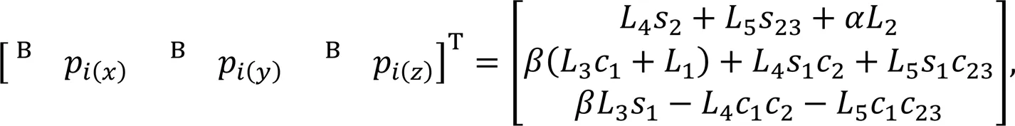
wherec=cos(q,j),s=sin(q,j),c=cos(q,j+q,k), s=sin(q,j+q,k),q,jrepresents theth joint of theth leg, and,∈{1, 2, 3} represent the three joints, HAA, HFE, and KFE, respectively, as defined in Fig. 1a.,∈{-1, 1} are symbolic variables taking the following values:
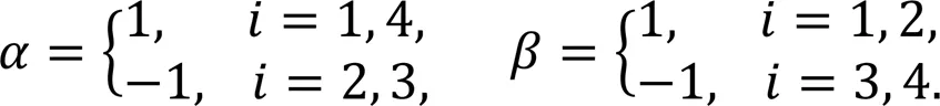

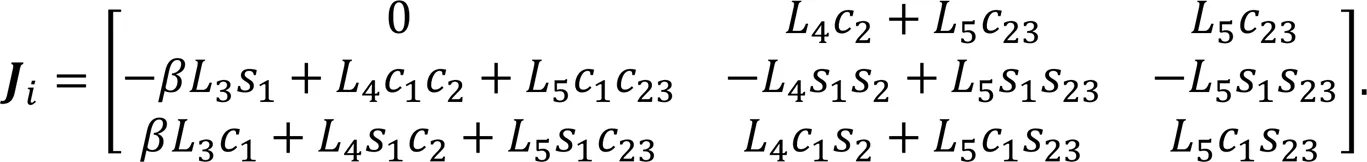
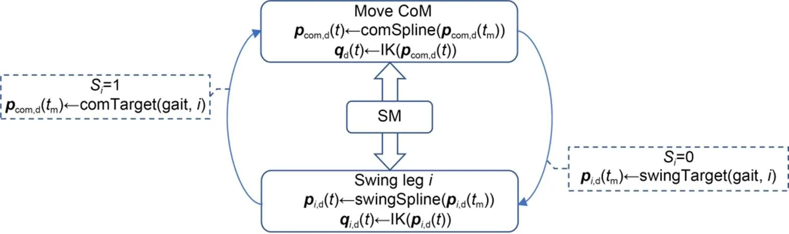
Fig. 6 Logic diagram of the state machine (SM). Rectangles represent the motion state, arrows indicate the direction of state transition, and dotted boxes represent related state-transition operations

The position of the CoM at timein world coordinates is then determined by

In the process of robot-state estimation, the measurements acquired from the sensors include high-frequency noise, which is removed by a first-order low-pass filter.
3.5 Optimization of the GRFs
To optimize the GRFs, we first computed the linear acceleration of the CoM and the angular acceleration of the base, and then solved for the GRFs using the simplified dynamics model.
3.5.1Dynamics of the simplified rigid body
The desired linear acceleration of CoM and angular acceleration of the robot were designed under the PD control law (Focchi et al., 2017) as
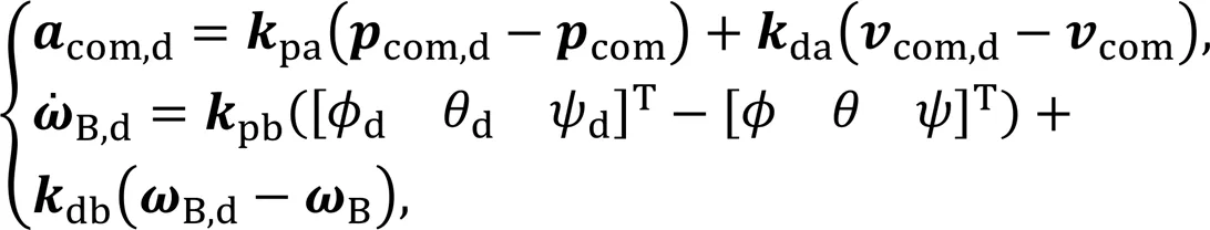
As more than 70% of the robot mass is concentrated in the base, the robot can be simplified as a single rigid body, in which the CoM coincides with the geometric center of the body (di Carlo et al., 2018). We further assume that the feet cannot generate moments when contacting the ground and that the GRFs are the only external forces acting on the robot.
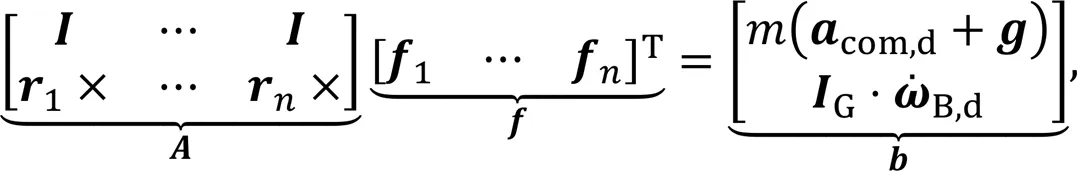
3.5.2GRF distribution
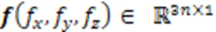
Eq. (16) constitutes six equations with 6–12 (depending on gait) unknown values of. Therefore, Eq. (16) can have an infinite number of solutions. Under certain constraints, the problem of solving this simultaneous set of equations can be transformed into an optimization problem of quadratic programming.
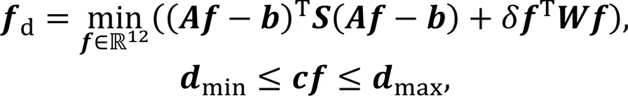
We set the following objective function:
From an energy-consumption perspective, motion efficiency is usually measured as the transport cost (CoT) (Zhou et al., 2021):
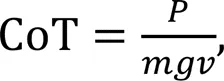
whereis the electrical power, andis the locomotion velocity of the robot.
CoT is proportional to the electric powerwhen the locomotion velocity is constant. Moreover, under normal working conditions,is proportional to the joint torque, and a corresponding relationship exists between the joint torques and GRFs (see later Eq. (25)). Therefore, penalizing the GRFs means implicitly minimizing the CoT.
Standard quadratic programming is given by
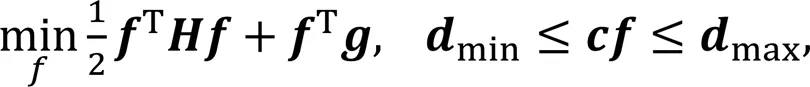
where
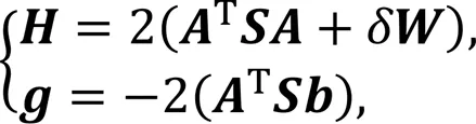
under the following constraints.
(1) Constraints on the upper and lower bounds of the GRFs:
(2) Constraints by the friction cone (approximated as linear friction to simplify the solution):
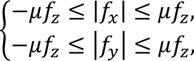
whereis the friction coefficient.
(3) Zero GRFs during the swing phase:
3.5.3Desired joint torques
The desired joint torques are obtained by summing the feedforward and feedback terms (Boaventura et al., 2012):
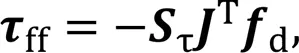
The feedback torques are computed as

When theth leg is in the stance phase (S=1), the gainspanddin Eq. (26) are set low, so the torquesdare mainly generated by the feedforward termsff. When theth leg is in the swing phase (S=0),ff=0 and the gains in Eq. (26) are set high, so the torquesdare entirely generated by the feedback termsfb.
4 Simulation and experiment
The stability of the locomotion-control strategy, based on dynamic planning of the CoM, was evaluated through simulations and experiments. We performed co-simulations in Matlab (R2018b) and V-REP (version 3.6.2). All experiments were implemented on the prototype shown in Fig. 1c, whose structure imitates the MIT Cheetah 3 robot. The controller parameters are listed in Table 2.
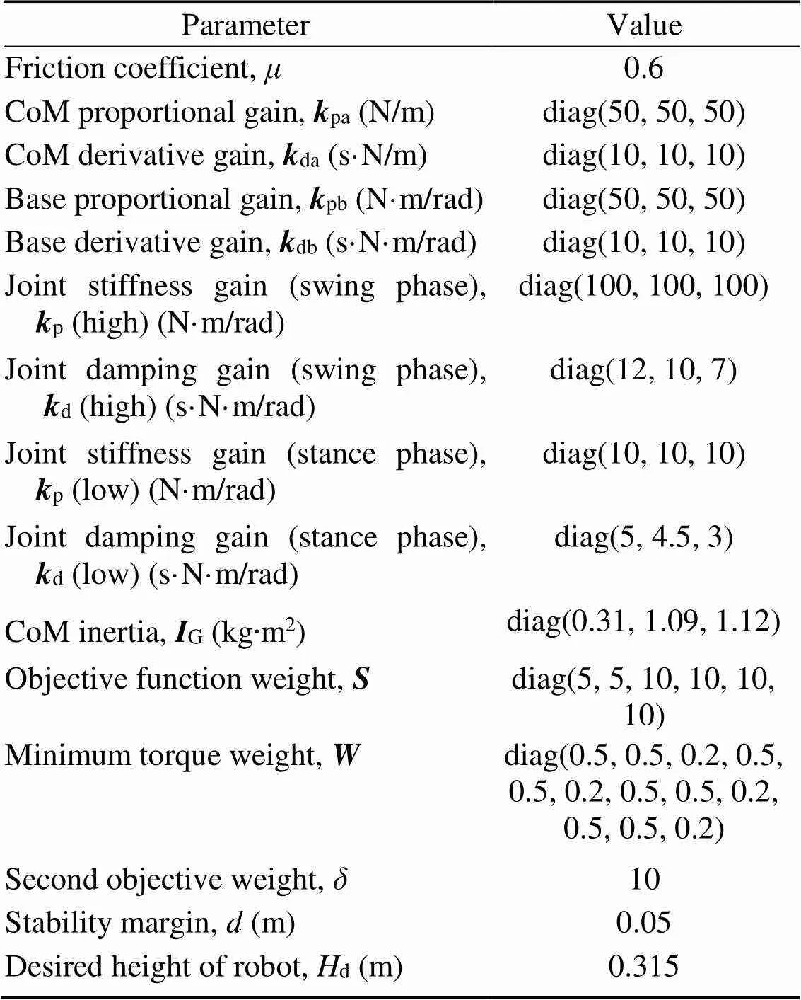
Table 2 Controller parameters
4.1 Omnidirectional locomotion simulation
Withv,d,v,d, andω,dset in Eq. (1), the robot moved along the- and-axis directions and rotated around the-axis, thereby achieving omnidirectional locomotion.
The desired velocities were specified as
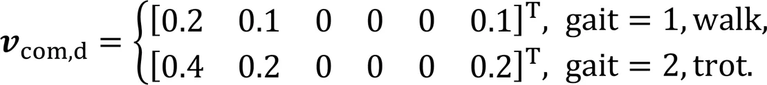
The simulation snapshots of the robot captured during omnidirectional locomotion are shown in Fig. 7. Whether walking (Fig. 7a) or trotting (Fig. 7b), the robot moved stably with the desired CoM velocity.
Fig. 8 shows the GRFs and joint torques of the RF leg during omnidirectional walking (Fig. 8a) and trotting (Fig. 8b). In the stance phase, the GRFs of the RF leg were mainly concentrated in thedirection and were very small in theanddirections. In contrast, during the swing phase of the RF leg, the GRFs were zero because the foot was above the ground. Additionally, when the RF leg was in the stance phase, the desired torques were mainly dominated by the feedforward terms, and the feedback terms were very small. When the RF leg was in the swing phase, the desired torques were wholly generated by the feedback terms because the feedforward terms were zero. These simulation results were consistent with the design scheme described in Section 3.5.
Fig. 9 shows the joint positions and velocities for the HAA, HFE, and KFE of the RF leg during walking (Figs. 9a and 9b) and trotting (Figs. 9c and 9d). The tracking errors between the desired and simulated values of each joint position and velocity were very small in both gaits, indicating that the simulated results matched the expected results.
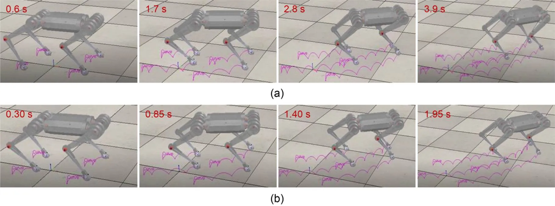
Fig. 7 Simulation snapshots of omnidirectional locomotion: (a) omnidirectional walking; (b) omnidirectional trotting
4.2 Omnidirectional locomotion experiment
Fig. 10 shows snapshots of the walking (Fig. 10a) and trotting (Fig. 10b) experiments, with the desired velocities set with Eq. (27). The robot completed the omnidirectional locomotion experiments in both gaits.
Fig. 11 presents the tracking of the CoM position and base orientation during omnidirectional walking and trotting. Figs. 11a and 11c indicate the positions of CoM in the,, anddirections in the two gaits, respectively. Figs. 11b and 11d indicate the roll, pitch, and yaw angles of the base in the two gaits, respectively. The simulated CoM and experimental CoM moved to the desired positions, and the errors in base orientation were very small. The positional and orientational tracking errors were slightly larger in the experiments than in the simulations in both gaits. Overall, the results matched expectations, verifying the correctness and effectiveness of the control strategy with CoM dynamic planning.
4.3 Tracking-error analysis
The robot moved at the desired CoM velocity (0.1 or 0.2 m/s along the-axis in the walk gait; 0.2 or 0.4 m/s along the-axis in the trot gait). The base orientations were observed during the experiments, and the tracking errors at the different velocities are depicted in Fig. 12. Presented are the major ranges and limits of the variations in the base orientations during walking (Fig. 12a) and trotting (Fig. 12b). Tracking fluctuations for Euler angles and root mean square errors (RMSEs) of the base orientations (Fig. 12c) increased slightly at higher velocities. The control capacity of the robot remained stable at different speeds, and the experimental results continued to align with the expected results.
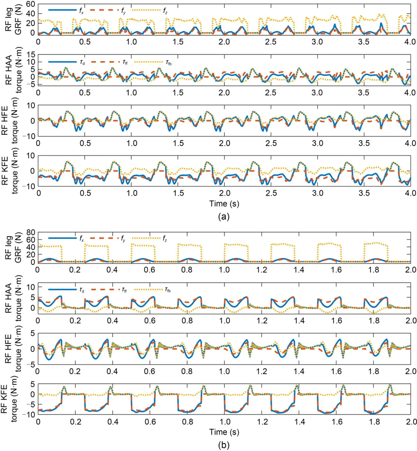
Fig. 8 GRFs and joint torques of RF leg in omnidirectional locomotion: (a) during walking; (b) during trotting
4.4 Comparison of stability and energy consumption
This subsection compares the stability of the robot under the control strategies with and without CoM planning. Here, the robot was governed to walk or trot atv,d=0.2 m/s. Fig. 13 shows the real-time stability margins for the robot during walking (Fig. 13a) and trotting (Fig. 13b).
The body was steady when the stability margin was positive, meaning that the CoM remained in the support triangle. Conversely, the body was unsteady when the stability margin was negative (i.e., the CoM was outside the support triangle). When the support triangle changed during a phase switch in the designed control strategy, the stability margin became negative for a very brief period before recovering (indicating a quick return of the CoM to the support triangle interior). Furthermore, after including CoM planning in the control strategy, the average stability margin and proportion of positive to negative stability margins (Fig. 13c) were improved by 0.0153 m and 27.25%, respectively, during walking, and by 0.0378 m and 37.25%, respectively, during trotting.
Finally, we compared the energy consumption of the robot when the objective function included or excluded ECO during walking and trotting atv,d=0.2 m/s. The real-time instantaneous powers and the mean GRFs (in thedirection) are shown in Fig. 14.
As shown in Fig. 14a, the control strategy with ECO in the objective function yielded a lower meanf(GRF in thedirection) than the control strategy without ECO. The comparisons were more evident in trotting than in walking; specifically, the GRFs decreased by 13.42% and 24.45% during walking and trotting, respectively. As shown in Figs. 14b and 14c, the instantaneous power-variation trends of the robot for the strategies with and without ECO were the same. The ECO reduced the GRFs of the legs in the stance phase, thereby decreasing the corresponding joint torques and the instantaneous power for the robot. Consequently, the control strategy with ECO reduced the average power by 11.25% and 13.83% during walking and trotting, respectively.
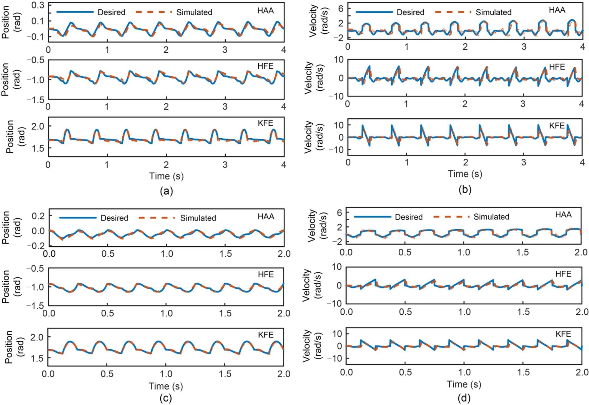
Fig. 9 Leg-joint positions and velocities of RF leg in omnidirectional motion: (a) leg-joint positions during walking; (b) leg-joint velocities during walking; (c) leg-joint positions during trotting; (d) leg-joint velocities during trotting
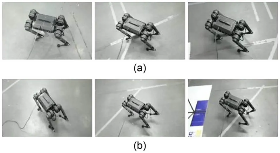
Fig. 10 Experimental snapshots of omnidirectional locomotion: (a) omnidirectional walking; (b) omnidirectional trotting
5 Conclusions
This paper proposes a novel control strategy with dynamic CoM planning for a quadruped robot. Comparing the control-scheme results with and without CoM planning, we demonstrated that the designed dynamic planning based on synchronous cooperation between the CoM and the swing legs could effectively improve the locomotion stability of the robot. When combined with ECO, the proposed control strategy reduces the locomotion energy consumption of the robot to a certain extent. The control strategy also extends the adaptation range of stability from the walk gait to the trot gait. The effectiveness of the designed control system was verified in simulation and experimental results for omnidirectional locomotion. Tracking-error analysis demonstrated that the controller operates well and enables steady locomotion at different velocities.
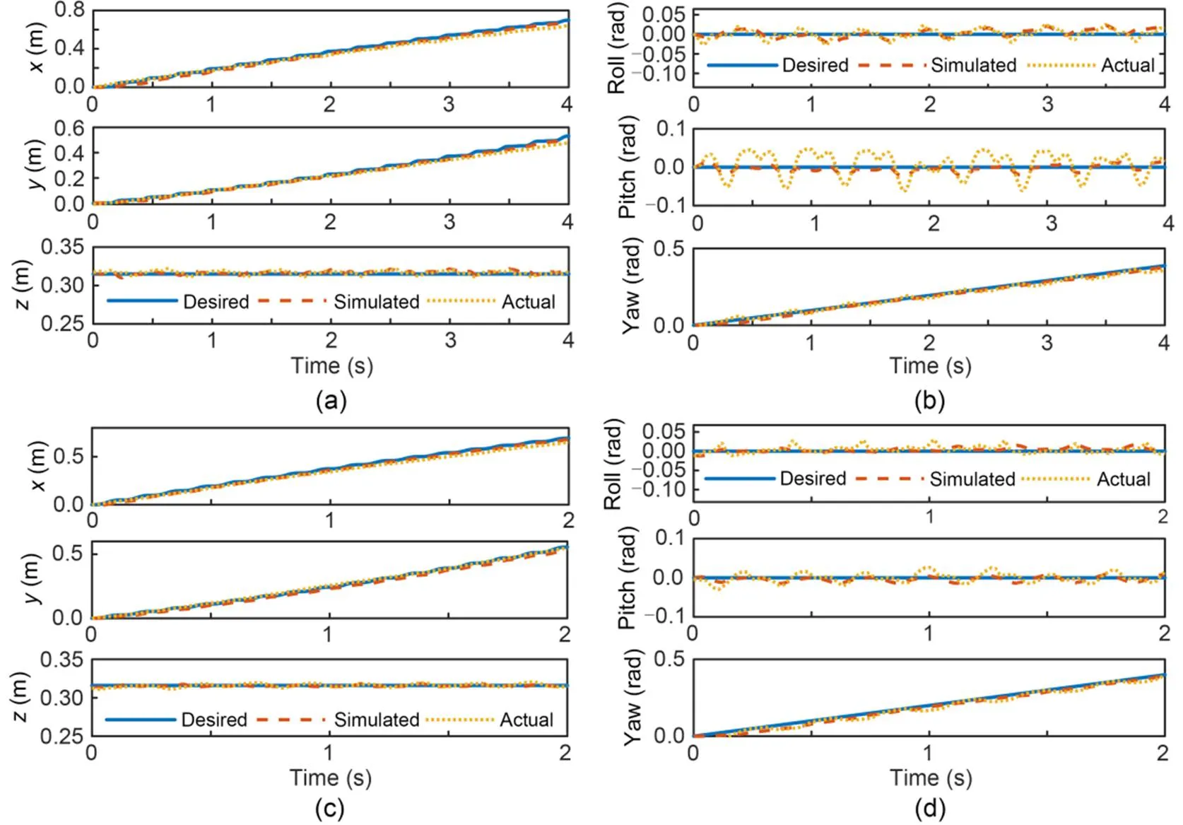
Fig. 11 Tracking of CoM positions and base orientations in omnidirectional locomotion: (a) CoM positions during walking; (b) base orientations during walking; (c) CoM positions during trotting; (d) base orientations during trotting. Solid, dashed, and dotted lines indicate the desired, simulated, and experimental results, respectively
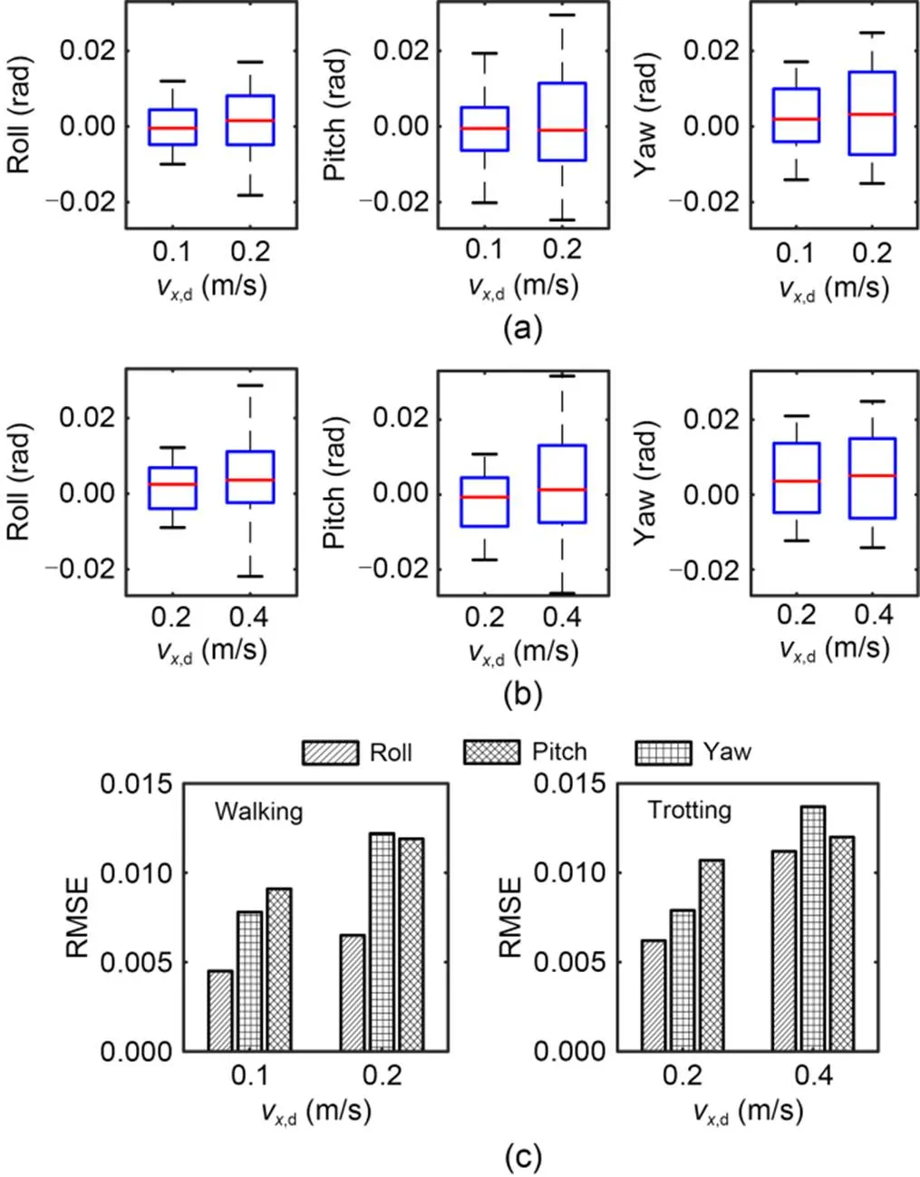
Fig. 12 Tracking errors of the base orientation: (a) boxplots of base orientation during walking; (b) boxplots of base orientation during trotting; (c) bar plots of the tracking errors (RMSE) for both walk and trot gaits
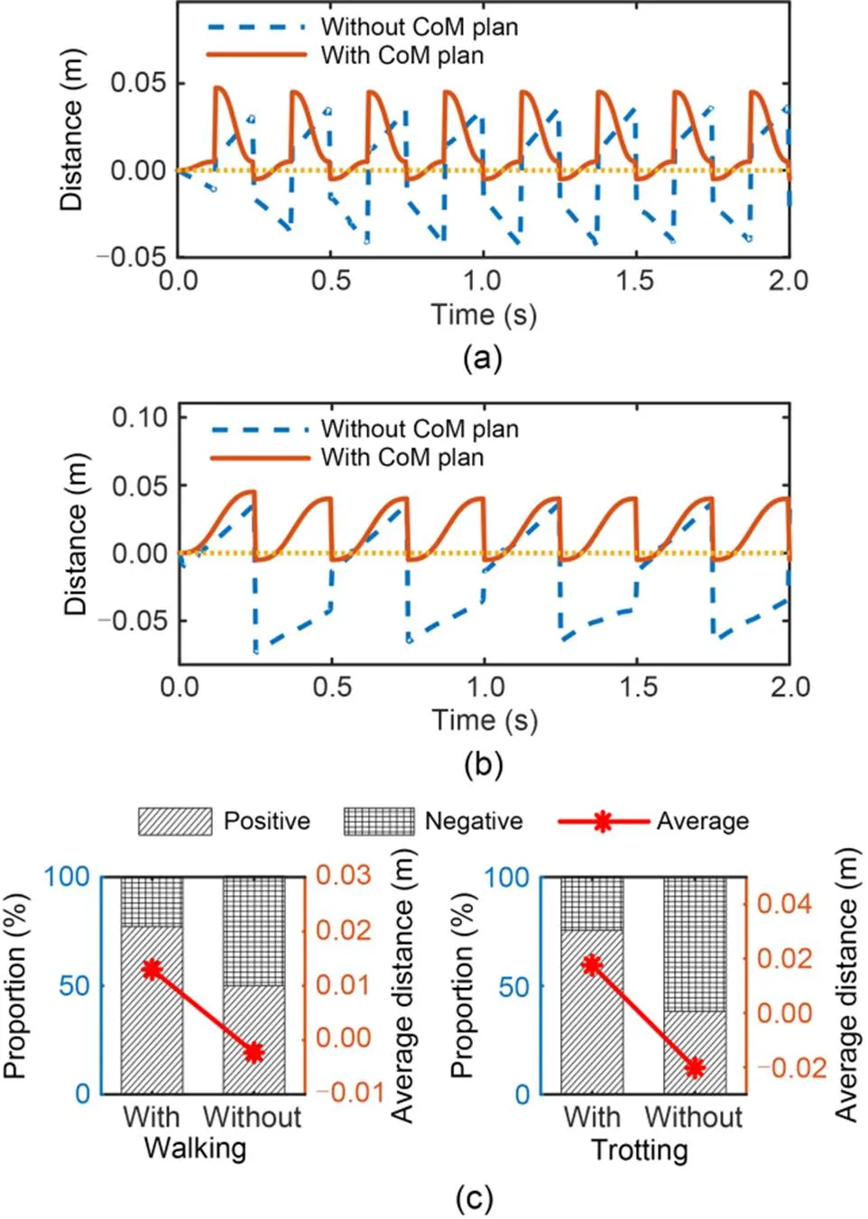
Fig. 13 Stability margins with two control strategies: (a) during walking; (b) during trotting; (c) proportions and averages of stability margins
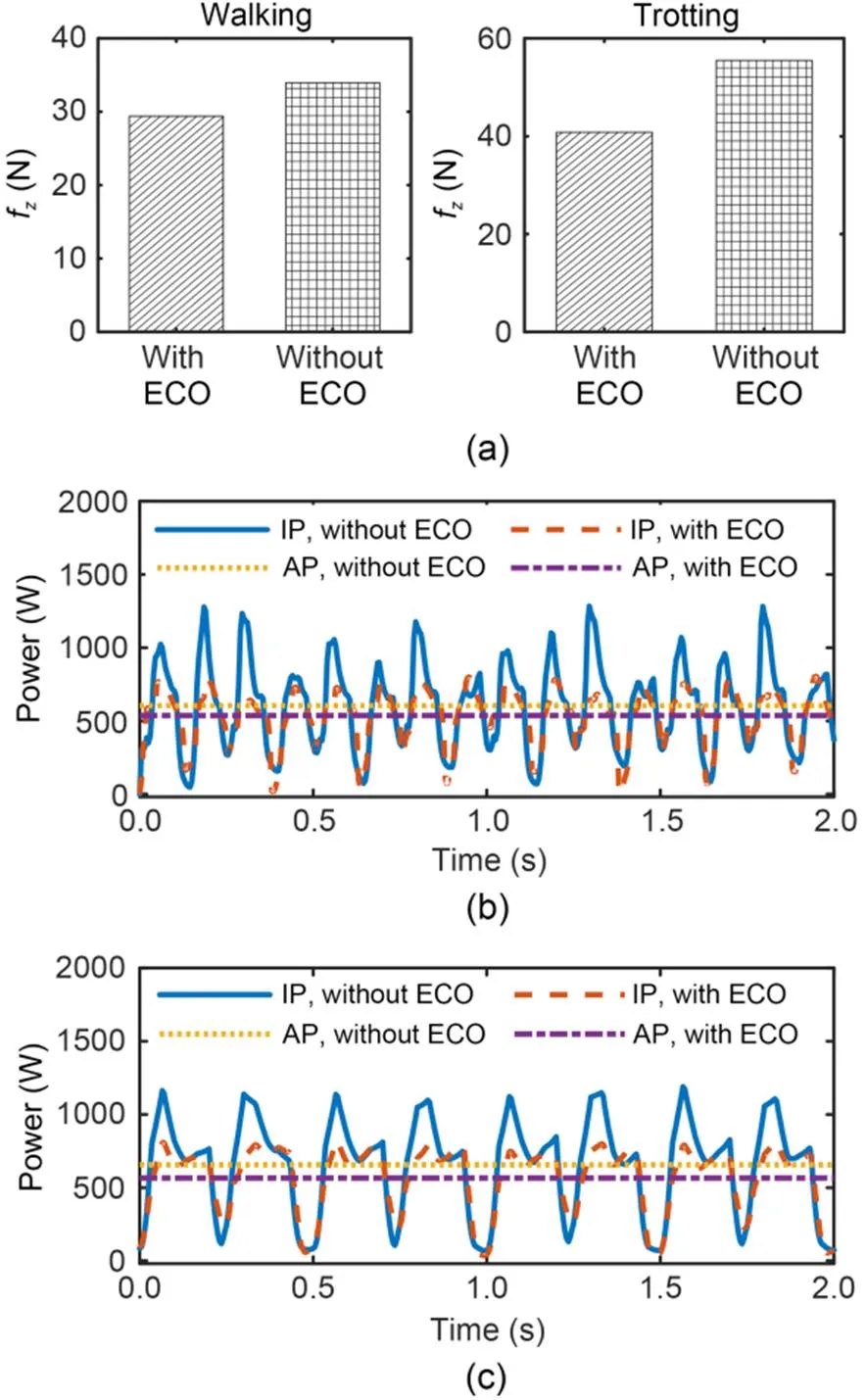
Fig. 14 Comparison between control strategies with and without ECO: (a) bar plots of mean fz; (b) power during walking; (c) power during trotting. IP: instantaneous power; AP: average power
The control strategy was applied for the typical walk and trot gaits. Because the velocities of the CoM and gait type are pre-programmed, the robot cannot select its gait or velocity in an actual situation. Moreover, the robot was tested in a pre-set experimental scene rather than a natural terrain environment.
In the near future, we plan to incorporate the feedback network of an animal motor nervous system, as well as biological reflexes, into the control system to improve the bionic ability and intelligence of our prototype. We hope that a control system based on multi-level reflex modes will enhance the adaptive control ability of quadruped robots in unstructured terrain.
This work is supported by the National Natural Science Foundation of China (Nos. 52175050 and 52205059), the Outstanding Youth Science Foundation (No. 51922093), the Scientific Research Fund of Zhejiang Provincial Education Department (No. Y202148352), and the Graduate Innovation Special Fund Project of Jiangxi Province (No. YC2021-B031), China.
Yangyang HAN designed the research. Liyu GAO and Huaizhi ZONG processed the corresponding data. Yangyang HAN and Zhenyu LU wrote the first draft of the manuscript. Feifei ZHONG helped to organize the manuscript. Guoping LIU and Junhui ZHANG revised and edited the final version.
Yangyang HAN, Guoping LIU, Zhenyu LU, Huaizhi ZONG, Junhui ZHANG, Feifei ZHONG, and Liyu GAO declare that they have no conflict of interest.
Arena P, Patanè L, Sueri P, et al., 2021. A data-driven neural network model predictive steering controller for a bio-inspired quadruped robot., 54(17):93-98. https://doi.org/10.1016/j.ifacol.2021.11.031
Boaventura T, Semini C, Buchli J, et al., 2012. Dynamic torque control of a hydraulic quadruped robot. Proceedings of the IEEE International Conference on Robotics and Automation, p.1889-1894. https://doi.org/10.1109/ICRA.2012.6224628
Chignoli M, Wensing PM, 2020. Variational-based optimal control of underactuated balancing for dynamic quadrupeds., 8:49785-49797. https://doi.org/10.1109/ACCESS.2020.2980446
di Carlo J, Wensing PM, Katz B, et al., 2018. Dynamic locomotion in the MIT Cheetah 3 through convex model-predictive control. Proceedings of the IEEE/RSJ International Conference on Intelligent Robots and Systems, p.1-9. https://doi.org/10.1109/IROS.2018.8594448
Ding YR, Pandala A, Li CZ, et al., 2021. Representation-free model predictive control for dynamic motions in quadrupeds., 37(4):1154-1171. https://doi.org/10.1109/TRO.2020.3046415
Dudzik T, Chignoli M, Bledt G, et al., 2020. Robust autonomous navigation of a small-scale quadruped robot in real-world environments. Proceedings of the IEEE/RSJ International Conference on Intelligent Robots and Systems, p.3664-3671. https://doi.org/10.1109/IROS45743.2020.9340701
Focchi M, del Prete A, Havoutis I, et al., 2017. High-slope terrain locomotion for torque-controlled quadruped robots., 41(1):259-272. https://doi.org/10.1007/s10514-016-9573-1
Fukui T, Fujisawa H, Otaka K, et al., 2019. Autonomous gait transition and galloping over unperceived obstacles of a quadruped robot with CPG modulated by vestibular feedback., 111:1-19. https://doi.org/10.1016/j.robot.2018.10.002
Gonzalez de Santos P, Jimenez MA, Armada MA, 1998. Dynamic effects in statically stable walking machines., 23(1):71-85. https://doi.org/10.1023/A:1007993923530
Gonzalez C, Barasuol V, Frigerio M, et al., 2020. Line walking and balancing for legged robots with point feet. Proceedings of the IEEE/RSJ International Conference on Intelligent Robots and Systems, p.3649-3656. https://doi.org/10.1109/IROS45743.2020.9341743
Hao Q, Wang ZB, Wang JZ, et al., 2020. Stability-guaranteed and high terrain adaptability static gait for quadruped robots., 20(17):4911. https://doi.org/10.3390/s20174911
Hutter M, Gehring C, Jud D, et al., 2016. ANYmal–a highly mobile and dynamic quadrupedal robot. Proceedings of the IEEE/RSJ International Conference on Intelligent Robots and Systems, p.38-44. https://doi.org/10.1109/IROS.2016.7758092
Hutter M, Gehring C, Lauber A, et al., 2017. ANYmal–toward legged robots for harsh environments., 31(17):918-931. https://doi.org/10.1080/01691864.2017.1378591
Hyun DJ, Seok S, Lee J, et al., 2014. High speed trot-running: implementation of a hierarchical controller using proprioceptive impedance control on the MIT Cheetah., 33(11):1417-1445. https://doi.org/10.1177/0278364914532150
Lee C, An D, 2021. Reinforcement learning and neural network-based artificial intelligence control algorithm for self-balancing quadruped robot., 35(1):307-322. https://doi.org/10.1007/s12206-020-1230-0
Lin PC, Komsuoglu H, Koditschek DE, 2005. A leg configuration measurement system for full-body pose estimates in a hexapod robot., 21(3):411-422. https://doi.org/10.1109/TRO.2004.840898
Liu LQ, Zhang CR, 2020. Dynamic properties of VDP-CPG model in rhythmic movement with delay., 17(4):3190-3202. https://doi.org/10.3934/mbe.2020181
McClain EW, Meek S, 2018. Determining optimal gait parameters for a statically stable walking human assistive quadruped robot. Proceedings of the IEEE/RSJ International Conference on Intelligent Robots and Systems, p.1751-1756. https://doi.org/10.1109/IROS.2018.8593979
Park HW, Wensing PM, Kim S, 2017. High-speed bounding with the MIT Cheetah 2: control design and experiments., 36(2):167-192. https://doi.org/10.1177/0278364917694244
Pepe G, Laurenza M, Belfiore NP, et al., 2021. Quadrupedal robots’ gaits identification via contact forces optimization., 11(5):2102. https://doi.org/10.3390/app11052102
Raibert MH, 1986. Legged Robots That Balance. MIT Press, Cambridge, USA, p.44-56.
Shao YC, Jin YB, Liu XW, et al., 2022. Learning free gait transition for quadruped robots via phase-guided controller., 7(2):1230-1237. https://doi.org/10.1109/LRA.2021.3136645
Srinivas T, Madhusudhan AKK, Manohar L, et al., 2021. Valkyrie-design and development of gaits for quadruped robot using particle swarm optimization., 11(16):7458. https://doi.org/10.3390/app11167458
Tian J, Ma C, Wei C, et al., 2019. A smooth gait planning framework for quadruped robot based on virtual model control. Proceedings of the 12th International Conference on Intelligent Robotics and Applications, p.398-410. https://doi.org/10.1007/978-3-030-27538-9_34
Wang YQ, Ye LQ, Wang XQ, et al., 2020. A static gait generation for quadruped robots with optimized walking speed. Proceedings of the IEEE International Conference on Systems, Man, and Cybernetics, p.1899-1906. https://doi.org/10.1109/SMC42975.2020.9282997
Yeom H, Bae J, 2021. A dynamic gait stabilization algorithm for quadrupedal locomotion through contact time modulation., 104(3):2275-2289. https://doi.org/10.1007/s11071-021-06376-5
Zhang ML, Zhang YJ, He XL, et al., 2021. Adaptive pid control and its application based on a double-layer BP neural network., 9(8):1475. https://doi.org/10.3390/pr9081475
Zhang SS, Liu M, Yin YF, et al., 2019. Static gait planning method for quadruped robot walking on unknown rough terrain., 7:177651-177660. https://doi.org/10.1109/ACCESS.2019.2958320
Zhang Y, Wang H, Ding Y, et al., 2021. Adaptive walking control for a quadruped robot on irregular terrain using the complex-valued CPG network., 13(11):2090. https://doi.org/10.3390/sym13112090
Zhou LL, Li TF, Liu ZY, et al., 2021. An efficient gait-generating method for electrical quadruped robot based on humanoid power planning approach., 18(6):1463-1474. https://doi.org/10.1007/s42235-021-00089-6
Zhenyu LU, https://orcid.org/0000-0001-7784-5149
June 14, 2022;
Revision accepted Nov. 28, 2022;
Crosschecked Apr. 24, 2023
© Zhejiang University Press 2023
 Journal of Zhejiang University-Science A(Applied Physics & Engineering)2023年6期
- Journal of Zhejiang University-Science A(Applied Physics & Engineering)的其它文章
- Investigation of flow characteristics in a rotor-stator cavity under crossflow using wall-modelled large-eddy simulation
- Effect of additional cylinders on power-extraction performance of a Savonius vertical-axis wind turbine
- Compressive properties of a novel slurry-infiltrated fiber concrete reinforced with arc-shaped steel fibers
- Two-stage identification of interlayer contact loss for CRTS III prefabricated slab track based on multi-index fusion