Stacked arrangement of substrate integrated waveguide cavity-backed semicircle patches for wideband circular polarization with filtering effect*
Yitong YAO,Gang DONG,Zhangming ZHU,Yintang YANG
School of Microelectronics, Xidian University, Xi’an 710071, China
We present a novel broadband circularly polarized(CP)antenna with filtering effect for X-and Kuband satellite wireless communication.The structure comprises a driven layer (also a filtering layer)and a stacked layer (also a CP layer).The bandpass filtering response consists of two radiation nulls,which is the combined effect of a substrate integrated waveguide (SIW) cavity-backed aperture and embedded driven patch.The chamfered patch is introduced as the stacked component with the ability to achieve CP and widen the operating bandwidth.A prototype with a compact layout of 0.8λ0×0.71λ0×0.16λ0is fabricated using a multilayer printed circuit board(PCB)process for demonstration.Experimental results are in good agreement with the simulation results,and show that the measured-10-dB impedance bandwidth and 3-dB axial ratio (AR) bandwidth are 10.83% and 15.54%,respectively.In addition,a peak gain of 8.9 dBic for left-hand circular polarization (LHCP),an average in-band gainLHCP>7 dBic,and good frequency selectivity are obtained.
1 Introduction
The boon in satellite wireless communications over the past few years has resulted in a certain degree of congestion in conventional frequency bands.As a result,there will be a preference for higher frequency bands,such as X-and Ku-band,to meet the growing demand for capacity (Panagopoulos et al.,2004).
SIW exhibits superior performance in terms of highQvalue and low radiation loss (Li Y et al.,2012;Fan et al.,2017;Hu et al.,2018;Lorente et al.,2020).The most important feature of the SIW is that it is applicable to work with planar antennas,and the patch or slot supported by the SIW cavity is usually regarded as the last-order resonant element of the whole antenna structure (Awida and Fathy,2012;Han et al.,2019;Qi et al.,2021;Cao YY et al.,2022).A variety of SIW cavity-backed CP antennas suitable for X-and Ku-band have been presented(Guan et al.,2016;Huang et al.,2017).Guan et al.(2016)proposed a CP 4×4 array antenna based on SIW cavities,in which each element contains sequentially rotating slots.Huang et al.(2017)proposed a new radiating element architecture consisting of an SIW cavity and four etched slots.In spite of the improved gain,the array format inevitably leads to great area consumption.It also suffers from narrow bandwidth and there are few studies on the filtering effect of the patch antennas with the support of an SIW cavity.
Band pass filters (BPFs) and antennas are two critical components of the radio frequency(RF)front ends,and in general,they are designed independently and cascaded to enhance interference immunity (Cao YF et al.,2020).Integration of filters and CP antennas enables implementation of multiple functions while avoiding the transition loss associated with interconnections.The compactness makes it more suitable for assembly in miniaturized or portable devices,such as vehicle-mounted mobile devices,satellite communications,and handheld communication devices.In summary,CP filtennas are widely demanded for further improving radiation performance and system efficiency (Jiang and Werner,2015;Li TJ and Gong,2018;Wu et al.,2018;Tang et al.,2020;Wang et al.,2020;Ji et al.,2021).The bandpass filtering network and patch are located at different layers,as two distinct parts,to implement the co-design of wideband CP antennas(Jiang and Werner,2015;Wu et al.,2018;Tang et al.,2020;Wang et al.,2020).Simultaneously,the presence of the filtering network will come at the cost of extra area and additional power loss.Clockwise rotating CP patch antennas and cavity filters are combined in a 2×2 array (Li TJ and Gong,2018),and a folded antenna is created using a dual-mode(TE102/TE201)SIW cavity(Ji et al.,2021).Stacked arrangement of SIW cavity-backed patch antennas is a promising solution to overcome the increased design complexity associated with array-arrangement and higher-order resonant modes.
A bandwidth-enhanced SIW cavity-based stacked patch antenna is presented in this paper.The proposed novel design takes advantage of the bandwidth scaling properties of the stacked arrangement,while each layer is assigned a distinct function.Specifically,the driven patch is the core component for achieving the bandpass filtering effect,whereas the parasitic patch is used in concert with the slot to produce circular polarization.The compact stacked arrangement without introducing additional circuits resonates in fundamental modes and eliminates the necessity for array format.We exhibit the detailed antenna layout,explain the working principle,and discuss the relevant parameters.We also experimentally validate the feasibility in comparison with available achievements,and draw conclusions.
2 Antenna configuration and design
2.1 Configuration of the proposed antenna
The three-dimensional view of the proposed stacked architecture and a plan view of each layer are illustrated in Fig.1.The structure is made of four-layer dielectric substrates of Rogers 5880,consisting of three cavity layers and an isolation layer for mutual interference reduction.A 50 Ω grounded coplanar waveguide (GCPW) is adopted as a feeding element because of low return loss.The driven patch is embedded in the aperture supported by the SIW cavity,and two radiation nulls are introduced using its own resonant mode and hybrid coupling to produce a bandpass filtering effect.The chamfered semicircle patch on the top layer serves as the stacked patch,while collaborating with the slot to deliver CP radiation.Detailed dimensions of the intended antenna are listed in Table 1.

Fig.1 Configuration of the proposed antenna: (a)overall exploded view;(b) top view of substrate 1 and layer 1;(c) top view of substrate 2 and layer 2;(d) top view of layer 3;(e) top view of substrate 4 and layer 4 (SIW: substrate integrated waveguide;GCPW: grounded coplanar waveguide)
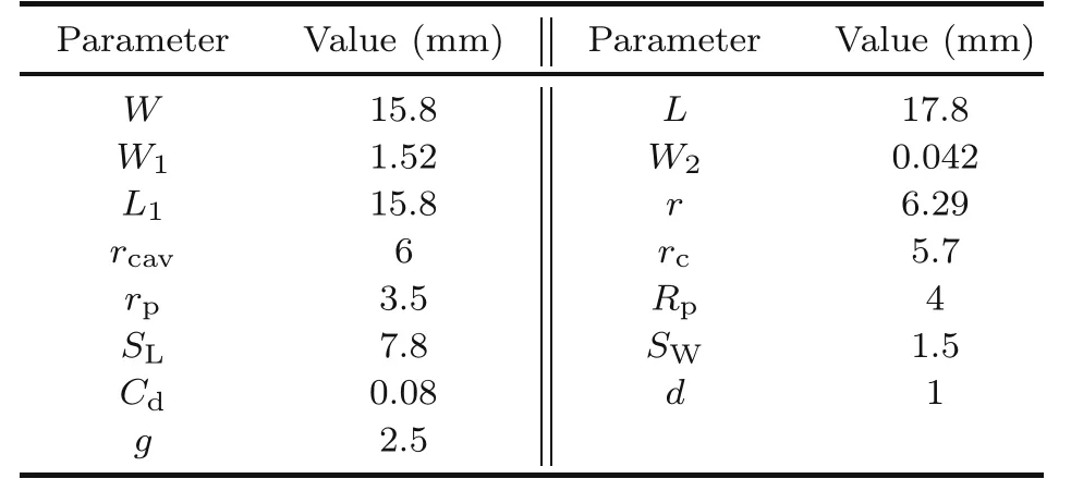
Table 1 Parameter list
2.2 Operating mechanisms
In an attempt to discuss the filtering and stacking characteristics more explicitly,the reference antenna without the stacked patch is introduced as demonstrated in Fig.2a.It is found that the electric field distributions of the TM110mode of the semicircle microstrip antenna in Fig.2b and the TM010mode of the circular SIW cavity in Fig.2c are comparable,and both are shifted to one side by the presence of the radiating slot.The suitability of these two modes for nested configuration to broaden the bandwidth can be inferred.

Fig.2 Reference antenna without the stacked patch(a),TM010 in the circular SIW cavity(b),and TM110 in the semicircle patch antenna (c) (SIW: substrate integrated waveguide)
BPFs typically consist of several coupled resonators,with a portion of the input energy maintaining resonance and the rest passing into the next resonator.The filtering function implemented in this design uses an SIW cavity resonator located in substrate 2 and a patch resonator embedded in the upper surface.The input signal is transmitted into the SIW cavity and then coupled to the driven patch through a modified aperture,while the patch antenna works as both a radiator and the last resonator of a BPF.Fig.3b illustrates the current distribution of the filtering layer at 6.5 GHz (null 1 at lower frequency),which is attributed to the centrosymmetric TM110mode of the driven patch.The currents along the edges of the embedded patch and the edges of the aperture are evidently in reverse directions.As a consequence,a radiation null is created toward the boresight due to the mutual attenuation of the far-field energy.Moreover,simultaneous electrical and magnetic coupling between the SIW cavity-backed aperture and the embedded patch will produce a second radiation null at a higher frequency of 14.99 GHz,according to the hybrid coupling theory.Fig.3 shows reflection coefficients and simulation realized gains of two antennas with and without the stacked patch.It is observed that the antenna with the stacked patch exhibits larger impedance bandwidth,more stability in gain,and more acute roll-offrates.
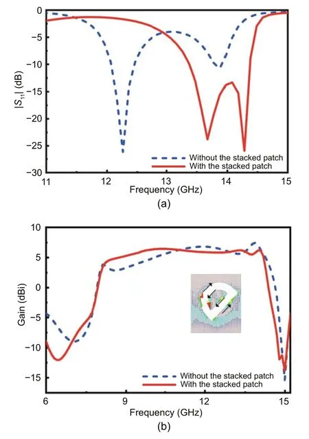
Fig.3 Simulation results of two antennas with and without the stacked patch: (a) |S11|;(b) gain
It is well known that the realization of CP requires two orthogonal components that satisfy specific preconditions.A phase difference of 90°and the equal magnitude correspond,respectively,to the conditions where the distance limit between the slot and the patch should beλ/5 and the rotation angle limit that the stacked patch should maintain is 45°.For each structural factor,the corresponding impact on the performance is discussed in Fig.4.A rotated semicircle patch is first used as a stacked component to cooperate with both the slot and the driven patch.Then,two corners are symmetrically chamfered as shown in Fig.1e to extend the operating bandwidth and sharpen the passband edges.This is partly due to the fact that corner-truncated patches will have more sides of different lengths to enable multi-frequency excitation of CP radiation.Since the electric field along the edge of the stacked patch has the same distribution as that of the driven patch,their far-fields will be superimposed in the direction of maximum radiation to strengthen the overall performance.Finally,an SIW cavity with two metal layers removed to avoid undesired coupling is introduced on the back side of the stacked patch to suppress surface waves and improve radiation efficiency.
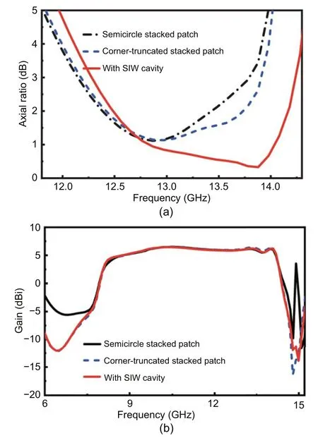
Fig.4 Simulation results of reference antennas and the proposed antenna: (a) axial ratio;(b) gain (SIW:substrate integrated waveguide)
2.3 Parametric study and current distributions
The parameters illustrated in Fig.1d are analyzed to investigate the influence of the SIW cavity and driven patch on the filtering property.As indicated in Fig.5,the patch radiusrpaffects null 1 by determining the microstrip resonant mode and further impacts null 2 by changing the mixed coupling relationship between the driven patch and the aperture.The distancegbetween the embedded patch and the top surface of the SIW cavity affects mainly the frequency of null 2,while null 1 is slightly affected because the driven patch is not changed.Taking into account the above factors and balancing the effects on the two nulls,the final values ofrpandgare chosen to be 3.5 mm and 2.5 mm,respectively.From lengthy discussion of the chamfered side (Cdas illustrated in Fig.1e),it can be inferred that the stacked patch with two symmetrically truncated corners could be available for tuning AR and beneficial to the filtering effect,which is confirmed in Fig.6.

Fig.5 Simulation gain curves versus patch radius rp(a) and distance g (b) between the embedded patch and top plane of the SIW cavity (SIW: substrate integrated waveguide)
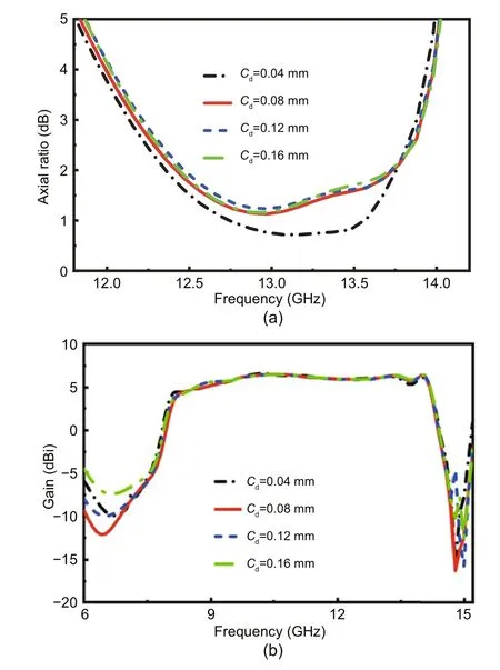
Fig.6 Simulation results of the proposed antenna with different Cd values: (a) axial ratio;(b) gain
Fig.7 depicts the phase-dependent current distribution of the top surface at the center frequency of its effective bandwidth,13.4 GHz.It shows that the maximum current is concentrated mainly at the edges of the stacked patch and the current direction across the entire patch is represented by black arrows for easy observation.As the phase increases,the arrows exhibit a clockwise rotation to produce the desired LHCP radiation.

Fig.7 Current distributions on a rotated cornertruncated patch at 13.4 GHz with different phases
3 Experimental results
A prototype is fabricated and measured for functional verification (Fig.8).Four nylon screws are used to achieve a tight connection between four substrates.Its return loss,radiation patterns,and gain are measured using the Agilent Technologies E8364B vector network analyzer and the Agilent Technologies E8363B vector network analyzer.
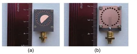
Fig.8 Fabrication of the proposed antenna: (a) top view;(b) bottom view
Fig.9 reveals that the experimental results are consistent with the simulation results.The measured-10-dB impedance bandwidth is 10.83% and the 3-dB AR bandwidth is 15.54%.As seen in Fig.9c,the measurement peak gainLHCP reaches 8.9 dBic and the average in-band gainLHCP is>7 dBic.The range of the 3-dB gainLHCP bandwidth of 8.37 to 14.08 GHz is slightly narrower than the simulated value.Limitations on manufacturing and testing errors may be responsible for these differences.Two radiation nulls are also introduced and sharp roll-offrates are obtained.The overall efficiency is>80% within the entire operating frequency band.However,the undesirable situation of inconsistent distribution of various parameters appears in the design of multilayer structures.The disagreement between|S11| and the antenna efficiency may be attributed to the fact that the GCPW is not directly connected to the driven patch and the parasitic patch,or even in the same resonant cavity.In this case,the indirect coupling of their positions weakens the interaction between them.In addition,the gain and AR in this design correspond to different aspects of CP radiation,resulting in discordance between their coverage bands.
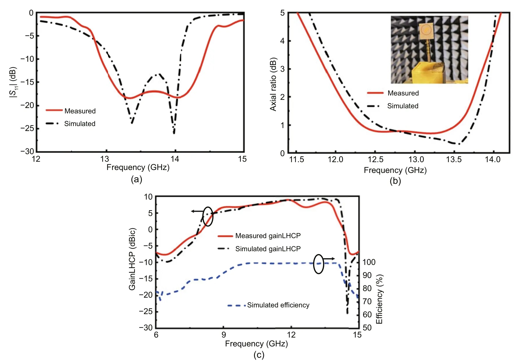
Fig.9 Simulation and measurement results: (a) |S11|;(b) axial ratio and measurement environment;(c)gainLHCP and efficiency (LHCP: left-hand circular polarization)
Simulation and measurement radiation patterns at resonant frequencies of 13.37 and 13.98 GHz are shown in Fig.10.It can be observed that the expected stable broadside radiation characteristics are achieved in both thexoz-plane andyoz-plane.Detailed performance of the proposed CP filtenna and the other reported CP filtennas are listed in Table 2.By comparison,this design achieves the most stable and the widest 3-dB gain bandwidth and good bandpass filtering response without any extra circuit.In addition,a wider AR bandwidth has been implemented to improve practicality for more convenient applications.

Fig.10 Simulation and measurement radiation patterns at 13.37 GHz (a)and 13.98 GHz (b) (LHCP: left-hand circular polarization;RHCP: right-hand circular polarization)

Table 2 Comparison with other reported CP filtennas
4 Conclusions
In this letter,a novel stacked CP antenna with filtering effect based on SIW technology is presented and fabricated for demonstration.Experimental results suggest that the structure produces a wide axial ratio bandwidth and stable gain with two radiation nulls by means of multiple coupling between SIW cavities,embedded driven patch,corner-truncated stacked patch,and radiating slot.Without additional filter circuits and utilization of dominant resonant modes,a wide range of applications in X-and Ku-band satellite wireless communication will be facilitated.
Contributors
Yitong YAO designed the research,processed the data,and drafted the paper.Gang DONG advised on the design process and helped organize the paper.Zhangming ZHU and Yintang YANG revised and finalized the paper.
Compliance with ethics guidelines
Yitong YAO,Gang DONG,Zhangming ZHU,and Yintang YANG declare that they have no conflict of interest.
Data availability
The data that support the findings of this study are available from the corresponding author upon reasonable request.
 Frontiers of Information Technology & Electronic Engineering2023年5期
- Frontiers of Information Technology & Electronic Engineering的其它文章
- Supplementary materials for
- Design and application of new storage systems
- Modulation recognition network of multi-scale analysis with deep threshold noise elimination*#
- COPPER:a combinatorial optimization problem solver with processing-in-memory architecture*
- DDUC:an erasure-coded system with decoupled data updating and coding*
- NEHASH: high-concurrency extendible hashing for non-volatile memory*
