Mesoscopic modelling of UHPCC material under dynamic tensile loadings
Xiang-zhen Kong ,Shang-in Yang ,Tao Zhang ,Qin Fang ,Heng-o Xiang ,** ,Rui-wen Li
a Engineering Research Centre for Safety and Protection of Explosion&Impact of Ministry of Education,Southeast University,Jiangsu Nanjing,211189,China
b State Key Laboratory of Disaster Prevention & Mitigation of Explosion & Impact, Army Engineering University of PLA, Jiangsu Nanjing, 210007, China
c Research Institute for National Defense Engineering of Academy of Military Science, PLA, Luoyang, 471023, China
d School of Civil Engineering and Architecture, Xi'an University of Technology, Xi'an, 710048, China
Keywords: UHPCC Dynamic tensile behavior Mesoscopic model Strain-rate effect Impact and blast loadings
ABSTRACT This paper presents a new 3D mesoscopic model of ultra-high performance cement-based composite(UHPCC)to investigate its dynamic tensile behavior.In this model,the UHPCC is regarded as a two-phase material composed of cementitious matrix and randomly distributed fibers.The model is established using the commercial software LS-DYNA and involves generating the randomly distributed fiber elements with considerations of diameter,length,orientation and volume fraction,and then fully constraining them with the matrix.In particular,to capture the slipping effect between fibers and matrix that has a strong influence on the dynamic tensile behavior,the fibers are modelled by a fictitious material represented by the load-slip relation.The strain-rate effect of slipping force neglected in most of previous studies is considered by calibrating constitutive parameters of the fictitious material under different strain-rates based on the single fiber pullout tests.Finally,the 3D mesoscopic model is validated against three sets of tension-dominated experiments covered a wide range of loading intensity.Numerical predictions demonstrate that strain-rate effect of slipping force must be considered,and the neglect of it may lead to a great underestimation of the dynamic tensile strength of UHPCC material and would unavoidably underestimate the blast resistance of UHPCC components.
1.Introduction
Ultra-high performance cement-based composite (UHPCC) is a new material with excellent mechanical properties,e.g.,the high compressive strength and modulus.In particular,the incorporation of fibers can effectively impede the crack propagation in the structure and significantly improve its ductility and energy absorption capacity [1-5].These prominent mechanical properties make it a potential material for protective structures to withstand extreme dynamic loadings such as impact and blast.
The dynamic behavior of UHPCC has been experimentally investigated extensively [6-10],in which the influences of specimen size,fiber type and volume fraction on the mechanical properties were discussed.In particular,its dynamic tensile behavior is of interest due to the natural complexity induced by the bridging effect of fibers between disconnected crack surfaces.Due to the bridging stress between disconnected crack surfaces induced by fibers,the strain-softening of UHPCC is more complex than traditional concrete and usually exhibits multiple stages.Macroscopical phenomenological models for describing the dynamic tensile behavior of UHPCC are usually incorporated in a material model which fully describes the dynamic behavior under complex loading conditions.The tensile-softening relation in the K&C material model [11]originally developed for traditional concrete was modified by Mao et al.[12]to capture the strain-softening of UHPCC under dynamic tensile loadings.This modification resulted a reasonable agreement with test data,but the fiber type and volume fraction that known have a strong influence on its tensile behavior cannot be considered.The tensile-softening relation and strain-rate effect parameters in tension of the K&C material model were further modified by Xu et al.[13]to numerically predict the impact tests on UHPCC specimens where tensile behavior is dominated.Although the numerical prediction results were reasonably consistent with the test data,the fiber type and volume fraction effects still cannot be considered.A set of parameters for tensile behavior in the concrete damage plasticity (CDP) material model was presented by Othman et al.[14],which was validated by dropweight impact tests on UHPCC slabs.Recently,Yang et al.[15]presented a four-stage tensile fracture model for UHPCC considering the bridging effect.The parameters in this model were calibrated by tensile stress-strain data of five volume fractions of micro-straight steel fibers.The dynamic responses of a UHPCC slab under blast loadings were reasonably reproduced.The macroscopical phenomenological models incorporated in a material model are simple and straightforward,which are very useful and convenient for protective structure design.However,the parameters needed in these models must be calibrated by corresponding tensile tests.These parameters must be adjusted accordingly when the fiber type and fraction volume change,which is time consuming and sometimes infeasible as dynamic tensile tests with specific fiber may be unavailable.Furthermore,the phenomenological models suffer from mesh-size dependency due to consideration of strain-softening [16].The numerical prediction of tension-dominated behavior pathologically depends on the mesh-size and orientation which limits the predictive capability of these models[17,18].As pointed out in Ref.[14],the description of dynamic tensile behavior of UHPCC in a material model is still a challenging topic and such phenomenological model has not been fully established.
The mesoscopic model provides another approach to study the dynamic tensile behavior of UHPCC.In the mesoscopic model,the matrix and fiber are separately modelled,and their interaction is considered by the built-in algorithm available in hydrocodes[19-24].In the mesoscopic model,modelling the slipping and pullout of fibers are the crucial since they are the main cause of the strain-softening and tensile failure of UHPCC material as pointed out in Ref.[15].A two-dimensional(2D)mesoscopic model of spiral fiber reinforced concrete(FRC)was established by Xu et al.[20],in which the mortar,aggregate and spiral fibers were separately modelled.This model was validated against the split Hopkinson pressure bar test on FRC specimens.However,the slipping between fiber and matrix is not considered as they are fully constrained with each other by sharing common nodes.The three-dimensional(3D)mesoscopic model for steel fiber reinforced concrete (SFRC)recently proposed by Zhang et al.[21]explicitly modelled the steel fibers in the concrete matrix composed of aggregate,mortar matrix and the interface transition zones (ITZs).The interaction between fiber and mortar matrix was also treated as perfect bond for simplicity,and consequently the slipping and pullout of fibers cannot be considered.Similarly,the 3D mesoscopic model for UHPFRC (ultra-high performance fiber reinforced concrete) proposed by Pontiroli and Erzar[22]used the perfect bond algorithm to describe the interaction of fibers and mortar matrix.To capture the slipping effect between fibers and matrix,a progressive 3D mesoscopic model for SFRC was proposed by Fang and Zhang[23],in which the randomly distributed fibers and matrix were modelled by beam element and tetrahedral solid element,respectively.The slipping effect was considered by the contact algorithm (Contact_1D in the LS-DYNA),in which the bond and slipping between the fiber and matrix was assumed to be elastic-perfectly-plastic depending on the shear modulus and relative shear strain between them.The model was validated against the dynamic responses of SFRC slabs subjected to impact and explosion.However,in this approach,the fibers and matrix must share common nodes when establishing the FE model,leading to a small mesh size when a high volume fraction of fiber is needed,which finally limits the computational efficiency.Furthermore,the parameters in the contact algorithm that are crucial for the description of slipping effect must be calibrated by trial-and-error based on the pullout test of single fiber,which is time consuming.The 3D mesoscopic model for SFRC recently proposed by Yang et al.[24]used the twonoded beam element and hexahedron solid element to model the fibers and matrix,respectively,in which the slipping between fiber and matrix was considered by an indirect method.In this method,it was assumed that the steel fiber would not be broken,so that the load-slip relationship can be transformed to the constitutive relation of steel fiber calibrated from the single fiber pullout test.This model was validated against the splitting tension test and flexural test.However,the strain-rate effect during the slipping were not considered.The strain-rate sensitivity of slipping force was experimentally observed in the single fiber pullout tests[25].The neglect of it may lead to the inaccurate prediction of dynamic tensiledominated failure in UHPCC.
It can be observed that only a few of existing mesoscopic models for UHPCC can consider the slipping effect.Furthermore,the experimentally observed strain-rate sensitivity of slipping force is rarely considered and discussed.To resolve these issues and give insights to the strain-rate effect of slipping force,a new 3D mesoscopic model for UHPCC is established in the present study.This involves generating the randomly distributed fibers with considerations of diameter,length,orientation and volume fraction in section 2 and then fully constraining them with the matrix.To capture the slipping effect between fibers and matrix,a fictitious material is used for fibers.Calibration of the constitutive parameters for fictitious fiber material under different strain-rates is presented in section 3,which is then validated by three sets of tensiondominated experiments in section 4.
2.Mesoscopic model for UHPCC
The UHPCC is regarded as a two-phase material composed of cementitious matrix and randomly distributed fibers.The generation algorithm of fiber elements is firstly conducted in this section,which are then fully constrained with the matrix.To capture the slipping and pullout of fibers,the fibers are modelled by a fictitious material represented by the load-slip relation.
2.1. Generation of randomly distributed fiber elements
Generally,the position and direction of fibers in the cementitious matrix are randomly distributed.The randomly distributed fibers should be modelled by beam element as the ratio of length to diameter is large enough.In the LS-DYNA,one beam element consists of three nodes,i.e.,the starting point(N1),the ending point(N2)and the orientation point(N3),as shown in Fig.1.The starting pointN1and ending point N2specify the length of beam element.The orientation point N3should be accurately determined for that with an I-shaped section,while it can be arbitrary for circularshaped section provided thatN1,N2andN3are not on a same line.
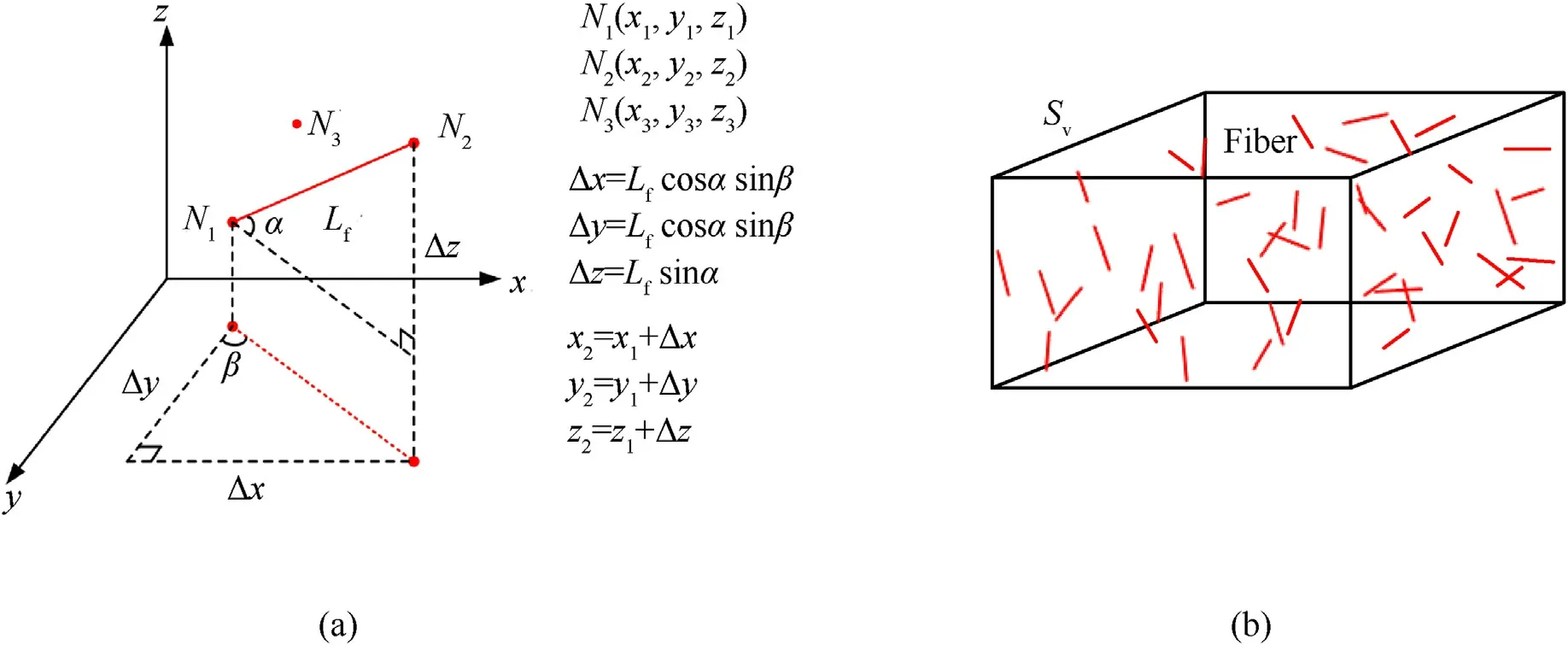
Fig.1.Generation of randomly distributed fiber elements: (a) Definition of one beam (fiber) element;(b) Fibers in a specific domain.
Assuming that each fiber is modelled by one beam element,the randomly distributed fiber elements can be generated as the following steps:
(1) Determine the number of fibers(Nf)needed to be distributed in a specific domain with a volume ofSv(Fig.1(b))based onNf=(4 ×Sv×Vf)/(π ×Lf×Df2),whereLf,DfandVfare the length,diameter and volume fraction of fibers,andSvis the volume of domain.
(2) Randomly generate theNf-number starting points of fiber elements with coordinates denoted as (x1,y1,z1).
(3) GenerateNf-number ending points of fiber elements with coordinates denoted as (x2,y2,z2) based on Eq.(1)
where α and β are a set of random angles shown in Fig.1(a).
(4) GenerateNf-number orientation pointsN3randomly provided thatN1,N2andN3are not collinear.
(5) Check if there are fibers interact with each other.If so,delete this beam element and then generated a new one as the steps above.
(6) Output theNf-number beam elements information to the format of LS-DYNA(known as“k”file),and then the FE model of fiber elements with random distribution is completed.An example is shown in Fig.2.
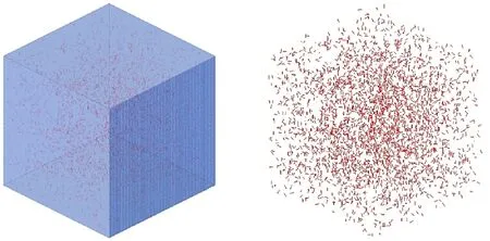
Fig.2.FE model of fiber elements with random distribution in the matrix.
It should be pointed out that the generation of fibers using the algorithm above is conducted in a specific domain.This domain is usually represented by the shape of a given specimen(including an irregular shape),and its geometric boundary can be easily determined.
2.2. Fictitious material to consider slipping effect
2.2.1.Constraint algorithm
Previous studies demonstrated that the slipping effect between fibers and cementitious matrix is the main mechanism to induce tensile-dominated failures in UHPCC [15].Therefore,it should be well considered in the mesoscopic model.In the LS-DYNA,there are three algorithms frequently used to consider the interaction of beam element(fiber)and solid element(matrix).The first one is the perfect bond algorithm in which the beam element and solid element are completely bonded with each other by sharing the common nodes so that the sliding effect cannot be considered[20,21],as shown in Fig.3(a).
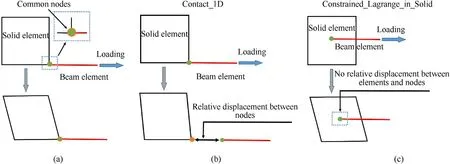
Fig.3.Three algorithms to consider the interaction of beam element(fiber)and solid element(matrix):(a)Perfect bond algorithm;(b)Contact algorithm;(c)constraint algorithm.
The second one is a contact algorithm(known as Contact_1D)in which the position of nodes for beam elements must be initially coincided with those for solid elements.Then the elastic-perfectlyplastic slipping force (also known as shear force) is calculated by relative displacement between nodes of beam elements and corresponding solid elements,as shown in Fig.3(b).This algorithm was previously used by Fang and Zhang [23]and was validated against the dynamic responses of SFRC slabs under impact and explosion.The disadvantage of this algorithm is obvious from two aspects.Firstly,the beam element and solid element share the common nodes initially,which leads to a small mesh size when a high volume fraction of fiber is needed,and consequently,the computational efficiency is limited.Secondly,the build-in slipping force model is an elastic-perfectly-plastic one,which may be too simple to consider the complex slipping and pullout of fibers under dynamic tensile loading,e.g.,the strain-rate effect.
The third one is a constraint algorithm that was originally developed for the fluid-structure (Euler-Lagrange) coupling analysis (known as Constrained_Lagrange_in_Solid),which is further extended to couple beam elements and solid elements.In this algorithm,the beam elements can be arbitrary distributed in the solid elements,as shown in Fig.3(c).This is very convenient for establishing the mesoscopic model of UHPCC than the other two algorithms where the beam element and solid element should share the common nodes.However,the beam elements and solid elements are completely bonded in this algorithm so that the slipping effect cannot be considered.
Previous tensile test on UHPCC material[26]demonstrated that the fibers are mainly pulled out from the matrix without broken at the crack positions,as shown in Fig.4.This results from the fact that the yield stress of fibers is significantly higher than the slipping stress between fibers and matrix.Based on this observation,an equivalent method is proposed here to consider the slipping effect,in which steel fibers are modelled by a fictitious material whose behavior is represented by the load-slip relationship.In other words,the load-slip relationship is transformed to the constitutive relation of steel fiber.This fictitious material method can model the complex slipping and pullout of fibers under dynamic tensile loading including the strain-rate effect by simply adjusting the constitutive parameters of the fictitious material which can be easily calibrated from existing single fiber pullout test [25].
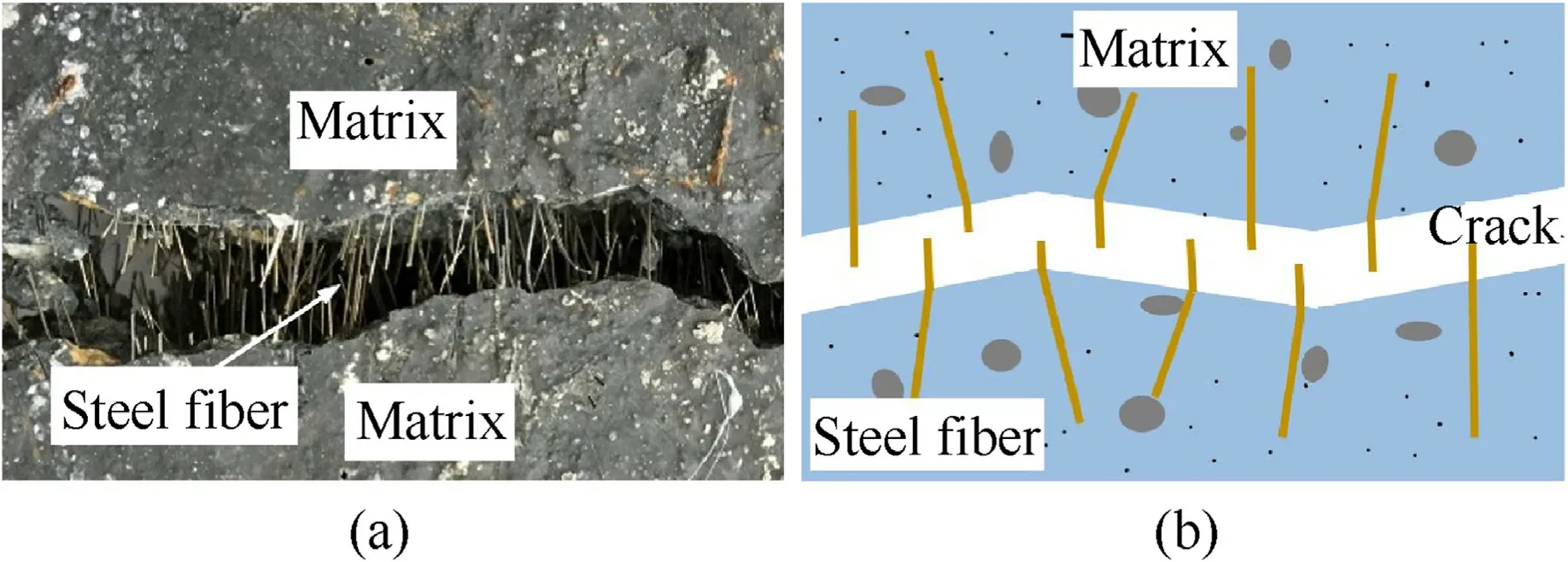
Fig.4.UHPCC fracture surface: (a) Experimental phenomena;(b) Schematic diagram.
2.2.2.Constitutive model forfictitiousfiber material
To model the complex slipping and pullout of fibers under dynamic tensile loading,the fictitious fiber material should be modelled by a constitutive model flexible for calibrating parameters.The piecewise linear plasticity constitutive model(*MAT_024 in the LS-DYNA) is used here,in which the plastic stress-strain curve is determined by a set of straight lines,similar to the hydro-elastoplastic model.The yield function φ is defined as
whereSijis the deviatoric stress tensor,and σyis the yield strength that can be defined as a curve vs.effective plastic strainby eight sets ofpoints.This makes the model flexible for fitting the complex load-slip relationship.The calibration of eight sets offor various type of fibers under different strain-rate will be given in detail in section 3 by corresponding single fiber pullout tests.
2.3. Material model for cementitious matrix
The cementitious matrix is modelled by the so-called Kong-Fang(KF) material model [27].It is an elastoplastic-damage based material model,which was originally developed for description of dynamic behavior of traditional concrete under impact and blast loadings and was extended to rock material recently[28].
In the KF model,the strength model and equation of state(EOS)defined the deviatoric behavior and spherical behavior,respectively.Two strength surfaces (the maximum one σmand the residual one σr)are adopted in the strength model and are defined as
wherea1anda2are material constants,fcis the compressive strength andTis the tensile strength.Prepresents the hydrostatic pressure,andDis the damage index.ψ is the ratio of tensile meridian to compressive meridian and is defined as
whereJ2is the second deviatoric stress invariant,andr′is the current meridian-to-compressive meridian ratio.The strain-rate effect is considered by radial enlargement of current fracture surface [29],in which the corrected strain-ratewas used instead of the frequently used instantaneous strain-rate,which is expressed as [18].
where η is the time scale governing the variation of strain-rate.
The compressive and tensile damage are separately defined by a modified effective plastic strain λ
The compressible damageDcand tensile damageDtare defined as
where α,c1andc2are material constants,and εfracis the fracture strain.ΔDtnamed as volumetric damage is additionally proposed to consider the damage accumulation when the current stress path approaches to the tri-axial tensile one.The total damage indexDis defined as
For completely describing the material behavior in the LS-DYNA,an EOS is needed.The EOS #8 in the LS-DYNA is used and not repeated here.Based on a large amount of numerical simulations and comparison with corresponding test data,the suggested parameters are given in Ref.[27]and listed in Table 1.

Table 1 Parameters of the KF model.
3.Parameter calibration for fictitious fiber material
As discussed above,the slipping effect (load-slip relationship)between the fibers and matrix is represented by the fictitious fiber material,which is modelled by the piecewise linear plasticity constitutive model where eight pairs of effective plastic strain and corresponding yield strength,i.e.,should be carefully defined.Previous studies demonstrated that the fiber type and load rate have a strong influence on the slipping effect,while the influence of cementitious material is negligible.Therefore,eight pairs ofare separately calibrated for various type of fibers under different strain-rate based on the single fiber pullout tests [25].
3.1. Single steel fiber pullout tests
Systematic single steel fiber pullout tests for UHPCC were conducted by Tai and El-Tawil [25].In these tests,the straight shaped(S-shaped),the hooked shaped(H-shaped)and twisted shaped(Tshaped)steel fibers were embed in the high-strength cementitious matrix(uniaxial compressive strength of 184 MPa)with inclination ranged from 0°to 45°.Experimental data showed that the inclination angles of the fibers had a small effect on the pullout force of the S-type fiber,and had almost no effect on the other two types of fibers.Therefore,the influence of fiber inclination angle is not considered in the mesoscopic model.Detailed information on the three types of fibers are shown in Fig.5 and Table 2.Note that the Sshaped steel fiber was made by the end-hook on the cut side of the H-shaped steel fiber.

Table 2 Detailed information of fibers.
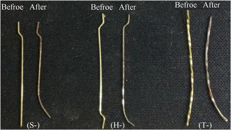
Fig.5.Three types of fibers [25].
As shown in Fig.6,the steel fibers were held by a well designed fixture on the testing machine,and were pulled out with loading rate ranged from 0.018 to 1800 mm/s corresponding to quasi-static loading rate to impact loading rate.To well represent the pullout of fibers,the effect of elongation of fibers should be reduced,and consequently,the free length of the fibers was minimized.The grip used to constrain the half dog-bone specimens were made of aluminum alloy.A laser sensor was used to measure the slip displacement between steel fiber end and matrix,so that the pullout force and slip displacement relation can be experimentally obtained.
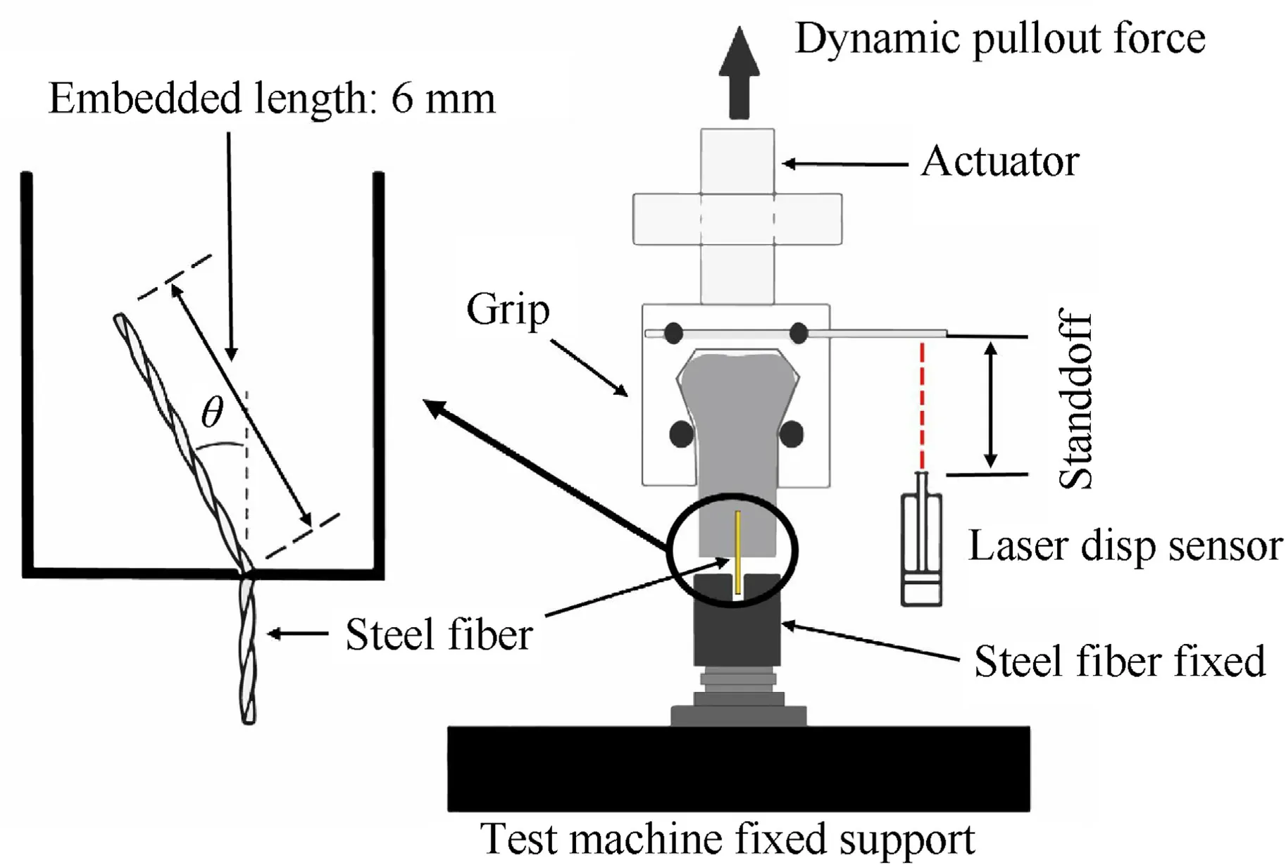
Fig.6.Setup for single steel fiber pullout test [25].
3.2. Numerical simulation and parameter calibration
The finite element (FE) model of the single steel fiber pullout test is shown in Fig.7.The high-strength cementitious matrix is modelled by a cubic specimen with side length of 30 mm,and is meshed by hexahedral element with a size of 1× 1 ×1 mm3.The single steel fiber is modelled by the beam element,and the interaction of beam element and solid element is considered by the constraint algorithm presented in subsection 2.2.1.The steel fiber is embedded in the cementitious matrix with a length of 6 mm,as consistent with the test.A velocity load same to the experiment is applied on the free end of fiber,and the steel fiber is considered as fully pulled out when the deformation of the fiber element reaches 6 mm.
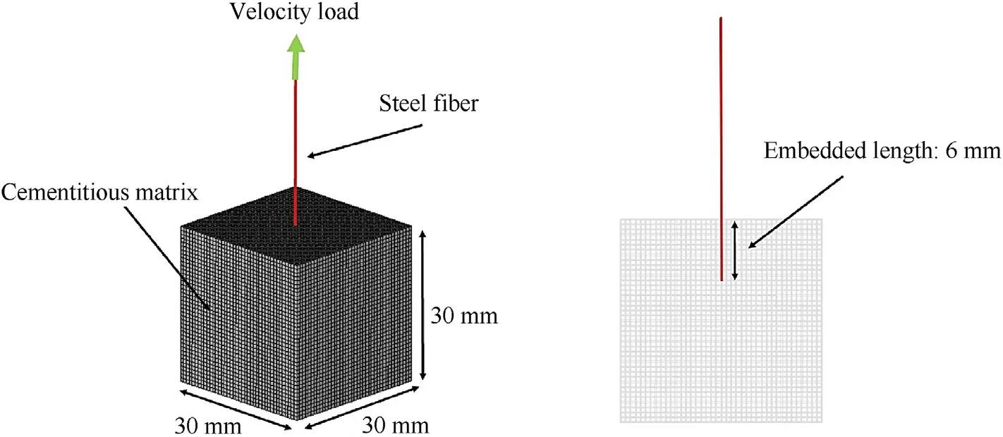
Fig.7.FE model of the single steel fiber pullout test.
The cementitious matrix is modelled by the KF material model and the parameters have been given in Table 1.The fiber is modelled by the fictitious fiber material represented by the linear plasticity constitutive model in which eight pairs ofshould be determined.Fig.8 presents the experimentally obtained pullout force-pullout displacement curves for S-shaped fibers under three loading rates,i.e.,quasi-static loading rate(strain-rate of 10-4s-1),seismic load rate (strain-rate ranged from 1 to 30 s-1) and impact loading rate (strain-rate of ranged from 100 to 150 s-1).It is obviously noted that the pullout force is strain-rate sensitive,and it increases with the increase of loading rate.These curves can be easily transformed to the fictitiousrelation by the following equations:
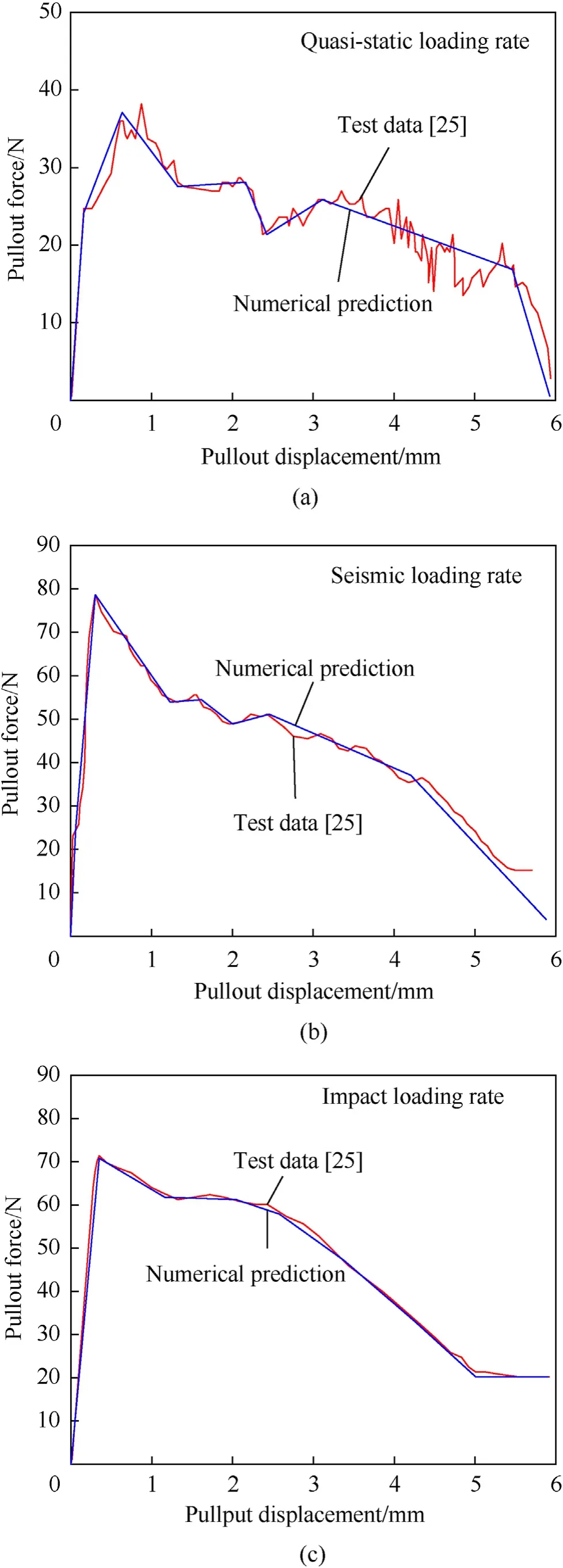
Fig.8.Comparison of numerically predicted pullout force-pullout displacement and corresponding test data under three strain-rates for S-shaped fibers: (a) Quasi-static loading rate;(b) Seismic loading rate;(c) Impact loading rate.
whereFis the pullout force,Sfiberis the sectional area of fiber.Lpdenotes the pullout length of fiber.
In general,the strain-rate effect of the pullout force observed in Fig.8 should be modelled by a rate-dependent material model.By introducing the well-known Cowper and Symonds model into the linear plasticity constitutive model,the strain-rate effect can be considered.However,this approach is not adopted here mainly because the lack of strain-rate data (only three strain-rates are available).Furthermore,the strain-rate not only affects the peak pullout force but the tendency of force-displacement curve,making it difficult for curve-fitting the strain-rate related parameters.With consideration of these aspects,the strain-rate effect is not explicitly modelled in the constitutive model.An alternative approach is used here in which the fictitiousrelation is separately defined for the quasi-static loading rate,seismic loading rate and impact loading rate.The obtained eight pairs offor the S-shaped fibers under the three strain-rates are given in Table 3.Although this is a primary approach,it can be used to simulate the dynamic tensile failure of UHPCC provided that the range of strain-rate in specific problems is clear.Nevertheless,the strain-rate effect can be explicitly considered in the fictitious fiber material by cooperating a strain-rate effect model,such as the Cowper and Symonds model,when the underling mechanism of rate sensitivity of pullout force is clear.
Table 3 Eight pairs of (,σy) for S-shaped steel fiber under different strain-rates.
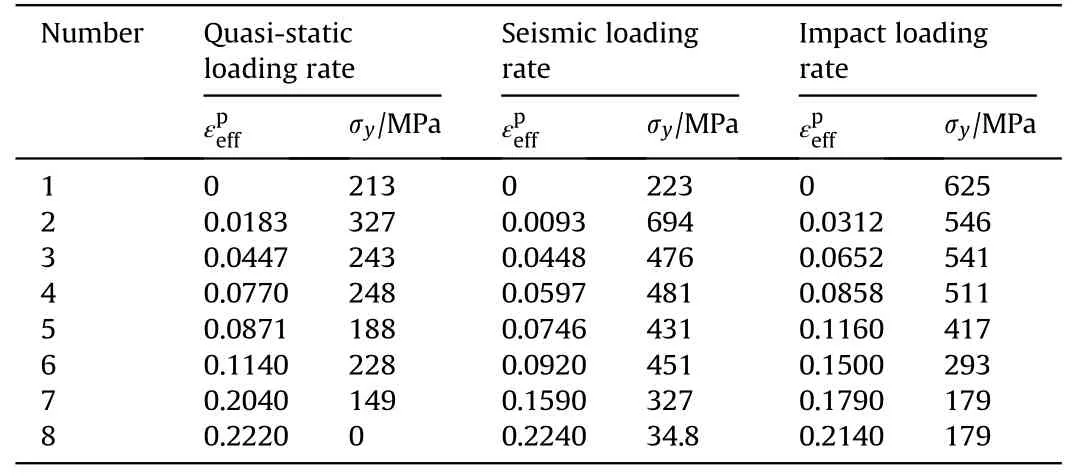
Table 3 Eight pairs of (,σy) for S-shaped steel fiber under different strain-rates.
Fig.8 shows the comparison of numerically predicted pullout force-pullout displacement and the corresponding test data under three strain-rates.The numerical predictions are consistent well with the test data,demonstrating the fictitious fiber material and corresponding parameters to describe the slipping effect.
Based on the same approach,the eight pairs offor the H-shaped fibers under the three strain-rates can be determined and given in Table 4.The corresponding comparisons of numerically predicted pullout force-pullout displacement and test data are shown in Fig.9.It is observed that the pullout force is much larger than that for S-shaped fibers with an identical pullout displacement,which means that the coupling effect between H-shaped steel fiber and cementitious matrix is stronger than the S-shaped ones,as expected.And the peak pullout force gradually increases from 200 to 260 N with the increase of the strain-rate.
Table 4 Eight pairs of (,σy) for H type steel fiber under different strain-rates.
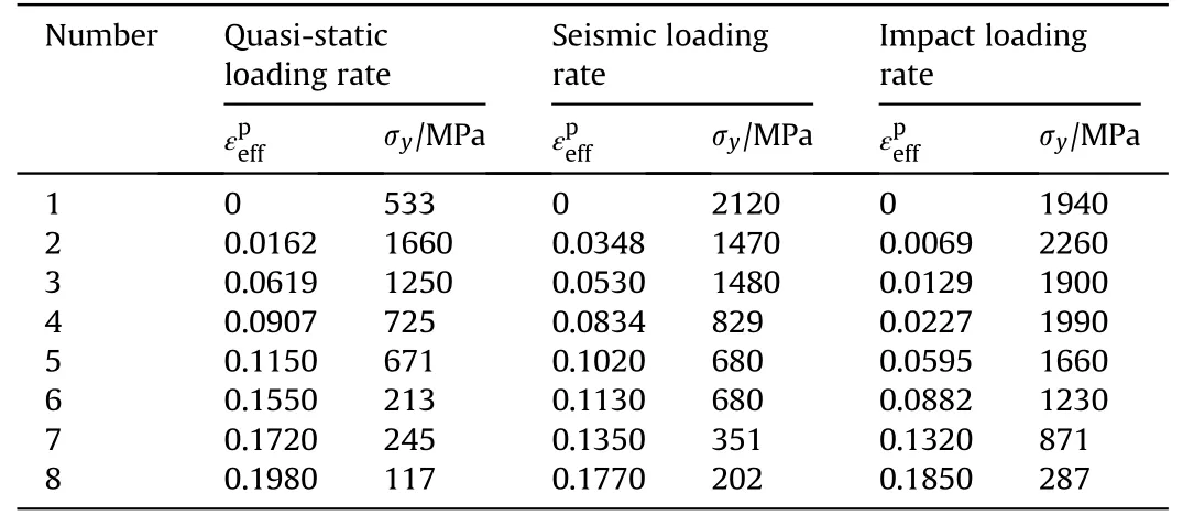
Table 4 Eight pairs of (,σy) for H type steel fiber under different strain-rates.
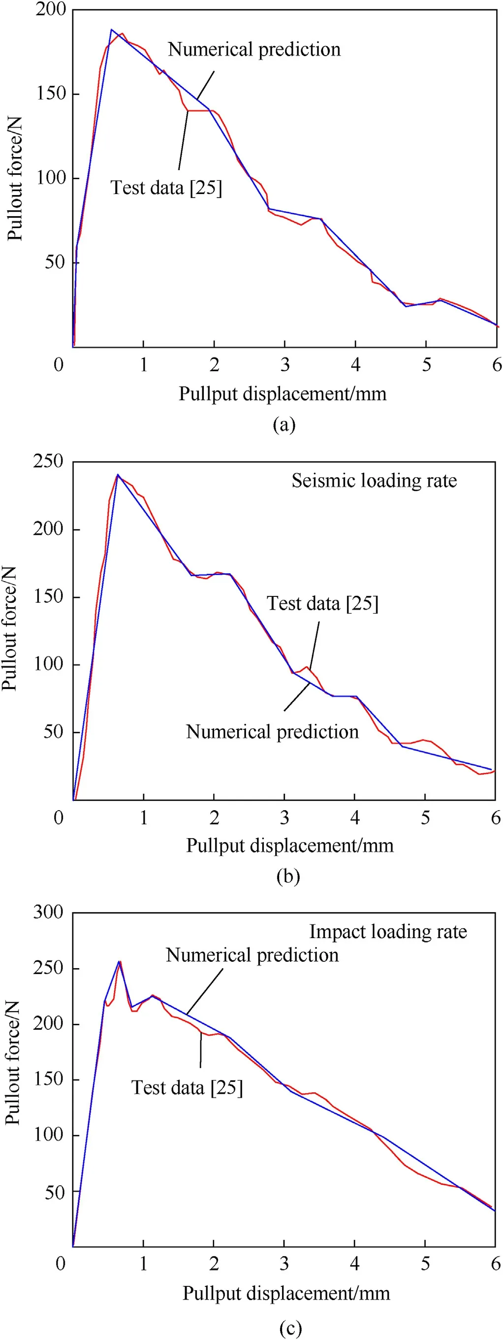
Fig.9.Comparison of numerically predicted pullout force-pullout displacement and corresponding test data under three strain-rates for H-shaped fibers: (a) Quasi-static loading rate;(b) Seismic loading rate;(c) Impact loading rate.
Similarly,the eight pairs offor the T-shaped fibers are determined and given in Table 5.Fig.10 presents comparisons of numerical predictions and test data.The coupling effect between Tshaped steel fiber and cementitious matrix is in the middle of Sshaped one and H-shaped one.The strain-rate sensitivity of pullout force can also be clearly observed.
Table 5 Eight pairs of (,σy) for T type steel fiber under different strain-rates.
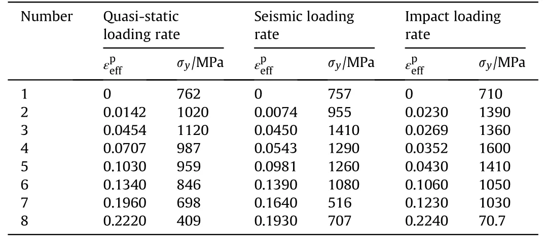
Table 5 Eight pairs of (,σy) for T type steel fiber under different strain-rates.
It can be observed that the fictitious fiber material approach can model the complex slipping effect between fibers and matrix flexibly by changing the parameters of the linear plasticity constitutive model.Compared with the contact algorithm,it is more convenient to establish the mesoscopic model as no further requirement is needed for the solid element and beam element,more flexible to describe the complex relation of pullout force and pullout displacement.Furthermore,the experimentally observed strain-rate effect of pullout force,which has been ignored in previous studies [19-24],can be appropriately considered in this approach.
4.Experimental validations
To further validate the constraint algorithm and fictitious material approach for the mesoscopic modeling of UHPCC,the tensile failures in UHPCC components are numerically simulated in this section.Special attention is drawn to the strain-rate effect of pullout force between fibers and matrix.The concerned loading rate ranges widely from quasi-static loading to very high blast loading rate.It should be pointed out that mesh-size sensitivity analysis is performed before every cases and the numerical simulations are insensitive to the mesh-size beyond a threshold value that is finally used for numerical simulation.
4.1. Four-point bending test on FRCC beam
Although the present mesoscopic model is proposed for UHPCC material,it can also be used for other fiber reinforced cementitious composites (FRCC).The four-point bending test on a short FRCC beam was conducted by Dong et al.[30].In this test,the beam has a cross section of 100 × 100 mm2and length of 350 mm.The cementitious matrix has a compressive strength of 56 MPa,elastic modulus of 40 GPa and Poisson’s ratio of 0.23.T-shaped steel fibers(0.3 mm in diameter,30 mm in length) are incorporated into the cementitious matrix with a volume fraction of 1.2%.The tensile strength and elastic modulus of the steel fibers are 2206 MPa and 200 GPa,respectively.As shown in Fig.11,the two ends of the beam are simply supported,and the deformation at the mid-span is recorded by the LVDT.
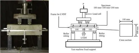
Fig.11.Test specimen and setup of the four-point bending test on FRCC beam [30].
The corresponding FE model is shown in Fig.12.The loading system,cementitious matrix and support system are modelled by solid elements with an element size of 2 × 2 × 2 mm3,while the steel fibers are modelled by beam elements.A time-dependent displacement load is applied at the top of the load cell.The interactions of the loading system,beam and support system are considered by the frictionless contact algorithm in the LS-DYNA.
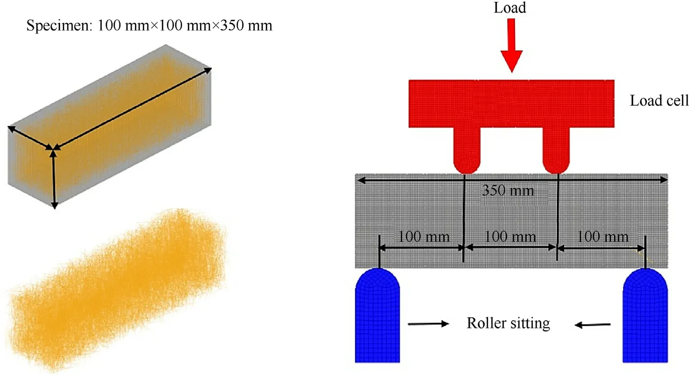
Fig.12.FE model of the four-point bending test on FRCC beam.
Using the fiber generation algorithm presented in section 2.1,the randomly distributed fiber elements can be established,which are then fully constrained with the solid cementitious matrix.The steel fibers are modelled by the fictitious material represented by the linear plasticity constitutive model with parameters given in Table 5,in which the eight pairs of effective plastic strain and yield strength for quasi-static loading rate are used.The loading and support systems are assumed as rigid body,since few deformations are observed in the test.The cementitious matrix is modelled by the KF material model with parameters given in Table 1.
It is known that the mesh size has a certain influence on the numerical predictions.Thus,the mesh-size sensitivity is conducted based on this four-point bending test,which is done by varying the mesh size as 1,2,4,8 mm and hold other conditions constant.The computational cost increases rapidly when the mesh size is smallerthan 2 mm,as shown in Fig.13(a).The influence of mesh size on the bearing capacity of the FRCC beam is shown in Fig.13(b).It is observed that numerically predicted bearing capacity decreases with the decrease of mesh size,and the numerical accuracy is not significantly improved when the mesh size is reduced to 2 mm.Therefore,the mesh-size of 2 mm is adopted by balancing the accuracy and computational cost.
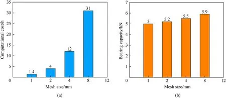
Fig.13.Influence of mesh size on (a) computational cost and (b) bearing capacity of the beam.
Fig.14 shows the comparison of numerically predicted reaction force-mid span deflection curve and corresponding test data.It is observed that the numerical prediction is basically agreed with the test data.The predicted peak reaction force is slightly higher than the test data,which may be caused by the fact that the constitutive parameters of the linear plasticity model are calibrated by the data for a high-strength matrix with a compressive strength of 184 MPa,while the cementitious matrix used in this test has a strength of 56 MPa.This leads to an overestimation of the pullout force,and consequently leads to a high peak reaction force.
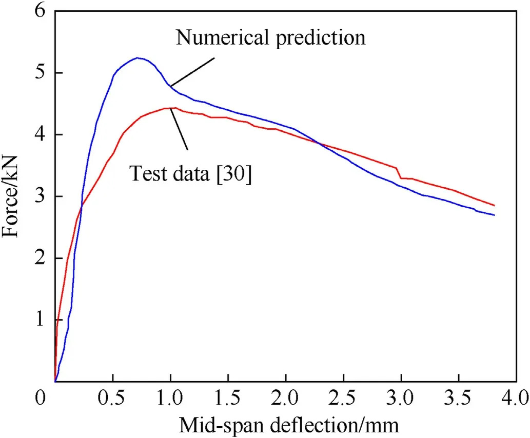
Fig.14.Comparison of reaction force-mid span deflection curves between numerical prediction and test data.
Fig.15 shows the numerically predicted damage in the cementitious matrix and equivalent plastic strain distribution in fibers during the loading process.It can be found that multiple cracks are uniformly distributed at the mid span of the cementitious matrix due to the tensile loading.The equivalent plastic strain of fibers reaches the maximum value in the piecewise linear plasticity material model(0.222 in Table 5)at the cracked position,which means that the fibers are gradually pulled out during the loading process and is consistent with experimental observation [30].
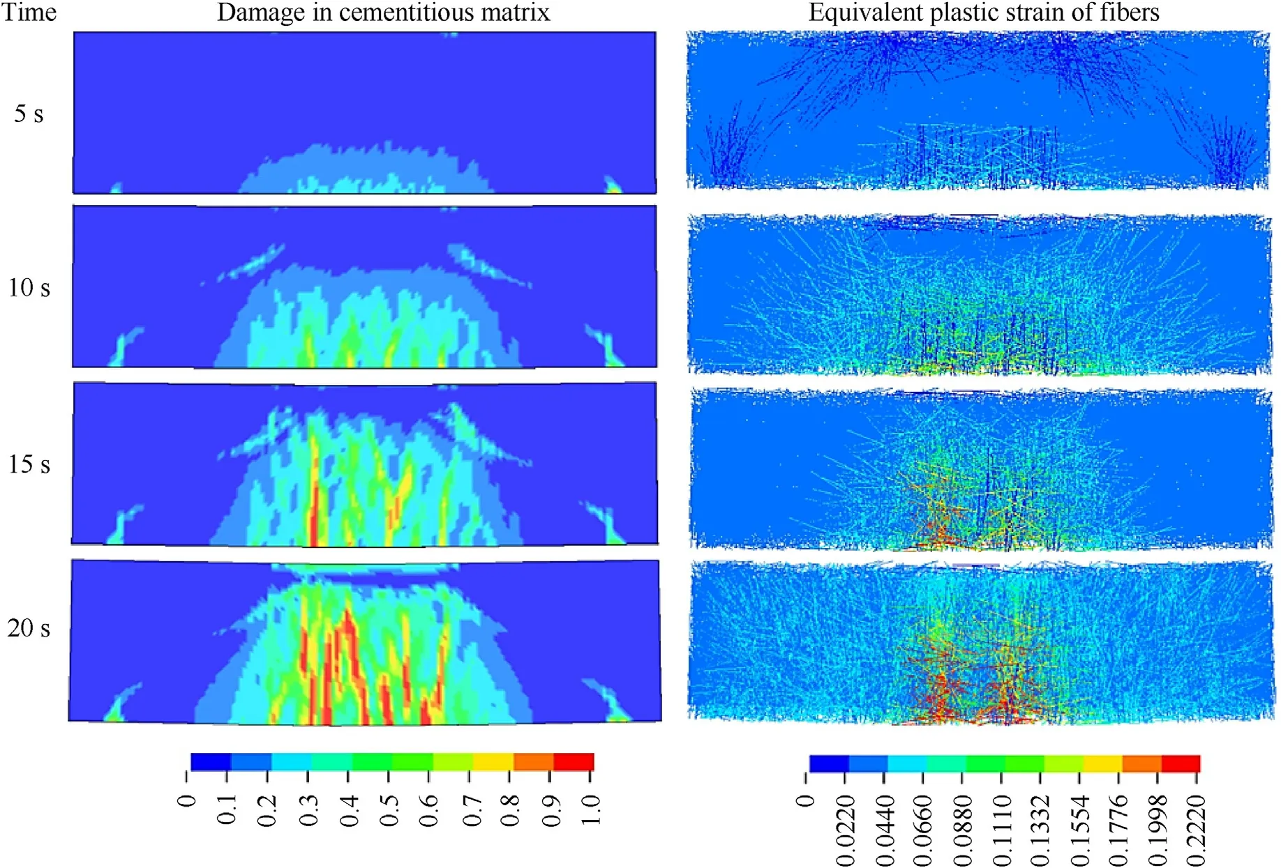
Fig.15.Numerically predicted damage in the cementitious matrix (left) and equivalent plastic strain distribution in fibers (right).
4.2. Dynamic tensile test on UHPCC specimen
The dynamic tensile test on UHPCC specimen at strain-rates of 32 s-1and 140 s-1was conducted by Park et al.[31].In this test,dynamic tensile loading is applied to the dog-bone-shaped UHPCC specimens with a cross section of 50 × 25 mm2and the gauge length of 50 mm,as shown in Fig.16.The compressive strength and elastic modulus of the cementitious matrix is 180 MPa and 50 GPa,respectively.The S-shaped steel fibers(0.2 mm in diameter,19 mm in length) are incorporated into the cementitious matrix,and the volume fraction is 2.0%.The tensile strength and elastic modulus of the steel fiber is 2206 MPa and 200 GPa,respectively.
As shown in Fig.16,one end of the UHPCC specimen is fixed by the grip while a dynamic tensile loading generated by a strain energy machine is applied to the other end constrained by a connector.The tensile force sensor located at the loading end is used to record the dynamic tensile force history,which can be easily transformed to the dynamic tensile stress history.The strain is measured by two strain gauges and digital image correlation using the images recorded by the high-speed camera.Therefore,the dynamic tensile stress-strain curve can be determined.
The corresponding FE model is shown in Fig.17.The connector,grip and cementitious matrix are modelled by hexahedral elements with the element size of 2 × 2 × 2 mm3,and the steel fibers are modelled by beam elements.Velocity loads are applied to the connector to ensure the strain-rates of UHPCC specimen as 32 s-1and 140 s-1.The connector and UHPCC specimen are considered as totally boned as there is no relative displacement between them after the test.The interaction of the grip and specimen is considered by the frictionless contact algorithm in the LS-DYNA.The randomly distributed fiber elements are established based on the proposed fiber generation algorithm,which are constrained with the solid matrix.The steel fibers are modelled by the linear plasticity constitutive model and parameters are given in Table 3,and the matrix is modelled by the KF material model.Both the connector and grip are assumed as rigid body.
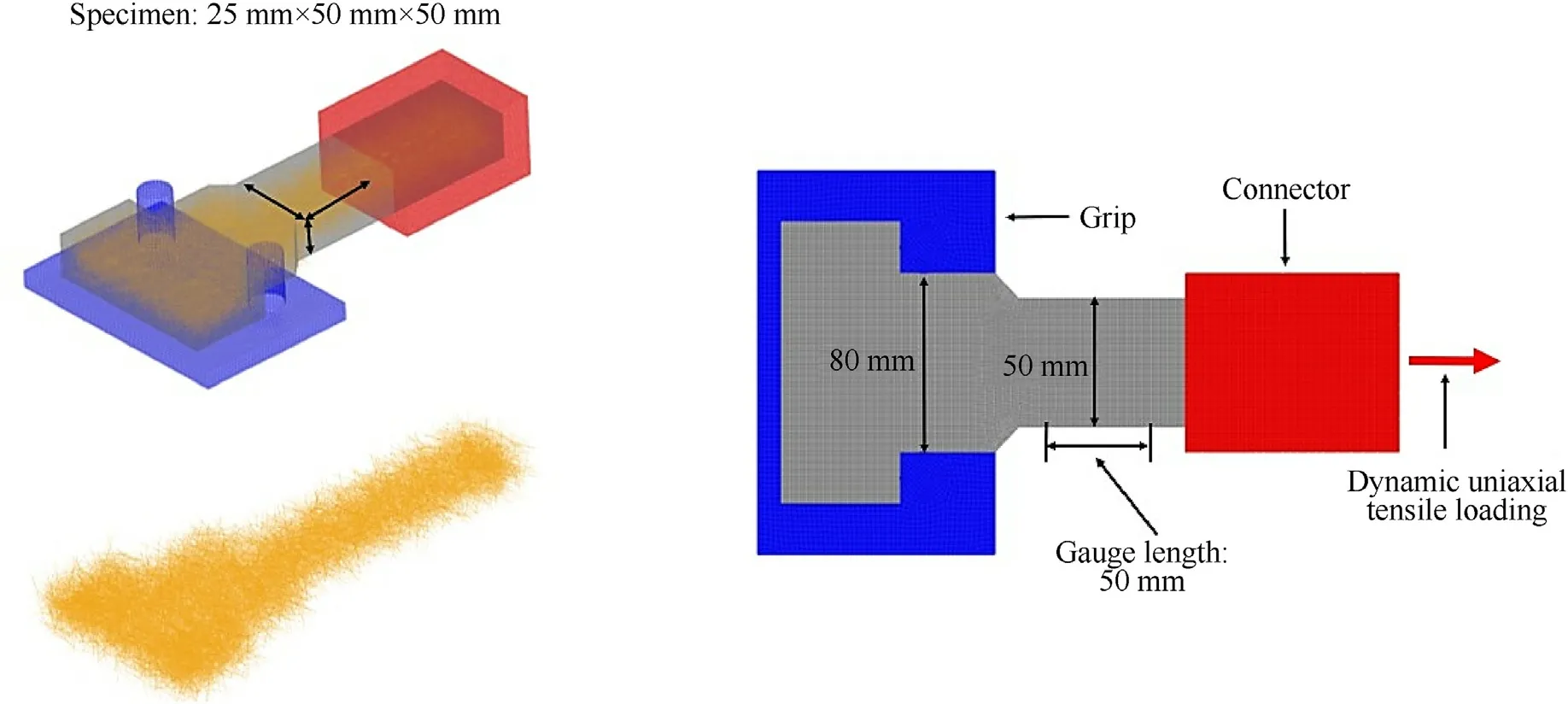
Fig.17.FE model of the dynamic tensile test on UHPCC specimen.
Fig.18 shows the experimental stress-strain curves under strain-rates of 32 s-1and 140 s-1along with the numerical predictions using three sets of (,σy) for quasi-static loading rate,seismic loading rate and impact loading rate.It can be observed that,for the test under the strain-rate of 32 s-1(Fig.18(a)),numerical prediction agrees with the data reasonably when using the(,σy)pairs for seismic loading rate(column two in Table 3).This can be easily understood since the(,σy)pairs for seismic loading rate are calibrated by the single steel fiber pullout tests under a strain-rate ranged from 1 to 30 s-1.While the numerical predictions greatly underestimate and overestimate the test data when the (,σy) pairs for quasi-static and impact loading rates are used,respectively.Similar phenomenon can be observed for the test under the strain-rate of 140 s-1(Fig.18(b)),in which the numerical prediction excellently agrees with the test data when using the(,σy)pairs for impact loading rate(column three in Table 3).However,the test data is greatly underestimated when using other(,σy) pairs.This demonstrates that the strain-rate effect of slipping force must be considered,as the neglect of it may lead to a great underestimation of the dynamic tensile strength of UHPCC material.
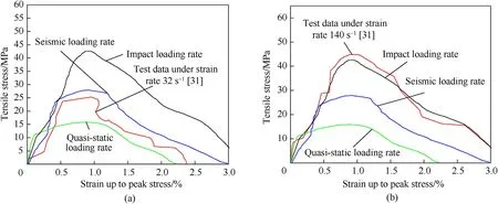
Fig.18.Comparison of experimental stress-strain curves under strain-rates of (a) 32 s-1 and (b) 140 s-1 and numerical predictions using different (,σy) pairs.
Fig.19 shows the numerically predicted crack pattern in the cementitious matrix and equivalent plastic strain distribution in fibers.It is observed that,for the strain-rate of 32 s-1,multiple cracks are almost uniformly distributed in the specimen between the grip and connector,and the tensile failure finally occurs at the position close to the connector where velocity load is applied.At this potion,the equivalent plastic strain for fibers reaches a maximum value of 0.224 (see Table 3),indicating the pullout of fibers.While for the strain-rate of 140 s-1,there is only one major crack in the specimen where the corresponding equivalent plastic strain for fibers reaches a maximum value of 0.214,which demonstrates that the dynamic tensile failure occurs here.These findings are consistent with experimental observation [31].
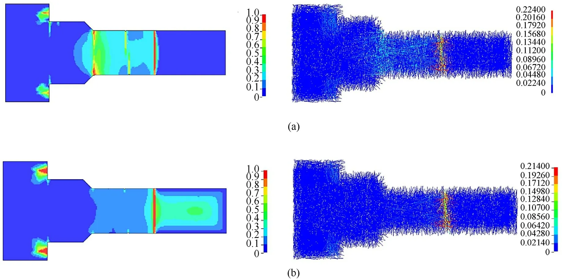
Fig.19.Numerically predicted crack pattern in the cementitious matrix (left)and equivalent plastic strain distribution in fibers(right) under strain-rates of(a) 32 s-1 and(b)140 s-1.
4.3. Explosion test on reinforced UHPCC slab
To further validate the constraint algorithm and fictitious material approach for the mesoscopic modeling of UHPCC,the explosion test on a reinforced UHPCC slab carried out by Li et al.[32]is simulated.In this test,the length,width and height of slab are 2000,1000 and 100 mm,as shown in Fig.20.The cementitious matrix has a compressive strength of 100 MPa and elastic modulus of 45 GPa.T-shaped steel fibers (0.3 mm in diameter,30 mm in length) are used and the volume fraction of fibers is 2.0%.The tensile strength and elastic modulus of the steel fiber are 2206 MPa and 200 GPa.The incorporation of fibers in the matrix results in the compressive strength of the UHPCC as 128.9 MPa.The UHPCC slab is reinforced by rebar with the elastic modulus 206 GPa and tensile strength 600 MPa,respectively.The arrangement of rebar is shown in Fig.21.The short edges of the slab are simply supported on a frame and the long edges are free.The blast loading was generated by a 14 kg-TNT explosive.A pressure sensor and a LVDT transducer were used to record the pressure on the slab and the deflection at the mid-span,respectively.
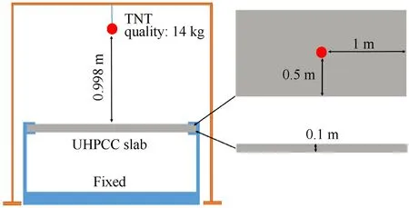
Fig.20.Test setup of reinforced UHPCC slab subjected to blast loading.
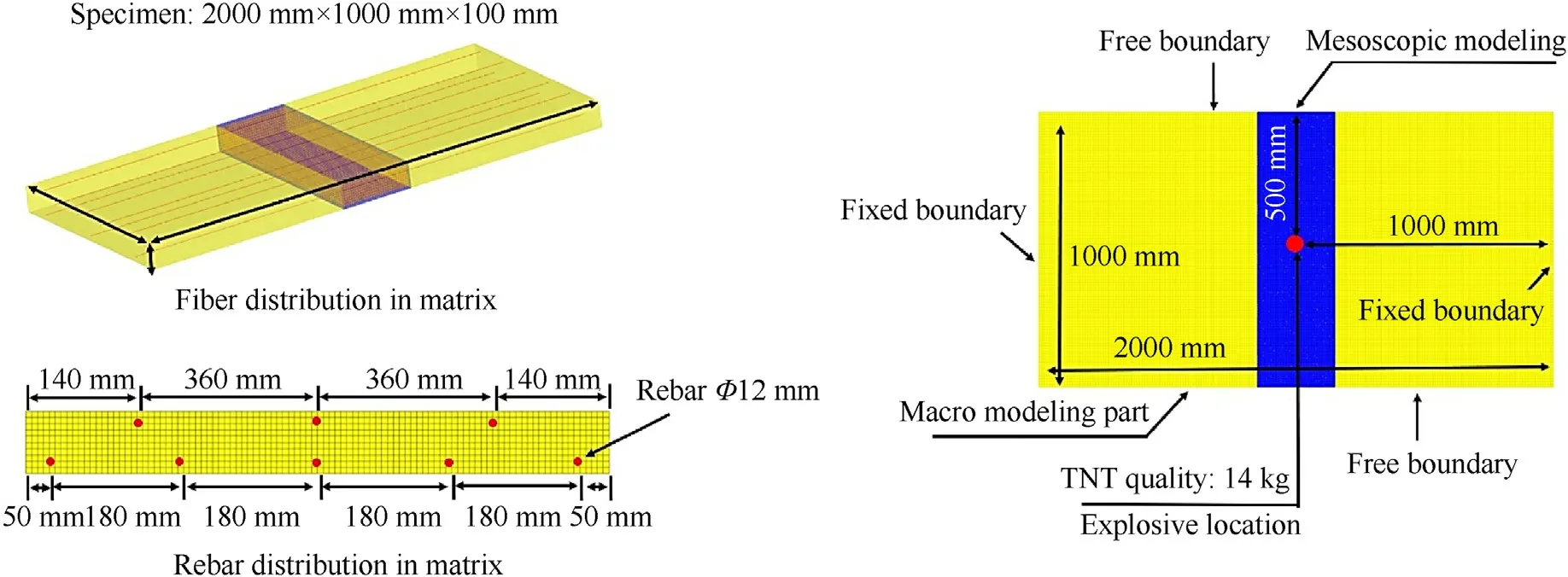
Fig.21.FE model of reinforced UHPCC slab subjected to blast loading.
Fig.21 shows the FE model.To save the computational cost,only the center part of the slab with a width of 300 mm is meshed by the mesoscopic model,while the UHPCC is considered as a homogeneous material for the other part.The two parts are fully bonded by sharing common nodes.Both the UHPCC part and cementitious matrix are modelled by hexahedron elements with the edge length of 10 mm and 5 mm,respectively.Both the reinforcement rebar and steel fibers are modelled by beam elements.The blast load is described by the *Load_Blast function in the LS-DYNA.The predicted overpressure on the slab by this function was verified by comparing the test data [32].
For the constitutive models,The UHPCC part adopts the modified KF model with parameters given in our previous study[15]and not repeated here.The randomly distributed fiber elements in the center part of the slab are generated with the proposed algorithm presented in section 2.1,and the fictitious material parameters for the T-shaped steel fibers are given in Table 5.The parameters of theKF model for the cementitious matrix are given in Table 1.The reinforcement rebar is modelled as an ideal elastic plastic material with elastic modulus of 206 GPa and yield strength of 600 MPa.
Fig.22 shows the comparison of numerically predicted midspan deflection-time curves using the three sets of (,σy) for quasi-static,seismic and impact loading rates in Table 3 along with the experimental permanent deflection.It can be observed that,numerical prediction agrees well with the data when using the(εpeff,σy)pairs for impact strain-rate(column three in Table 5).While the numerically predictions greatly overestimate the maximum deflection when the using other (,σy) pairs in Table 5.This further demonstrates that the strain-rate effect of slipping force must be considered,and the ignorance of it would unavoidably underestimate the blast resistance of UHPCC slabs.

Fig.22.Comparison of numerically predicted deflection-time curves and LVDT permanent deflection.
Fig.23 shows the numerically predicted cracks in the cementitious matrix and equivalent plastic strain distribution in fibers and the failure patterns observed from experiments.It can be found that cracks surrounding the mid-span are almost uniformly distributed,which mainly due to the bridging effect between fibers and matrix.The bridging effect changes the tensile failure of the slab from a major single crack to multiple uniformly distributed cracks.It is noted that the equivalent plastic strain in fibers does not reach its maximum value(0.224 in Table 5),indicating the fibers are not pulled out,which is consistent with the post-test observation shown in Fig.23 (c).

Fig.23.(a) Numerically predicted cracks in the cementitious matrix;(b) The equivalent plastic strain distribution in fibers;(c) the failure pattern observed from experiments.
5.Conclusion
In this study,a new 3D mesoscopic model of UHPCC is proposed to investigate its dynamic tensile behavior.This involves generating the randomly distributed fiber elements and then fully constraining them with the matrix.To consider the slipping effect between fibers and matrix,the fibers are modelled by a fictitious material represented by the load-slip relation,and the constitutive parameters of the fictitious material for various type of fibers under different strain-rate are systemically calibrated based on the single fiber pullout tests.The 3D mesoscopic model is validated by three sets of tension-dominated experiments with a wide loading rate.The main contributions and findings are as follows:
(1) The proposed 3D mesoscopic model of UHPCC can fully consider the diameter,length,orientation and volume fraction of the fibers.
(2) The slipping effect can be flexibly considered in the mesoscopic model using the concept of fictitious fiber material.
(3) Constitutive parameters of fictitious fiber material for three fiber types under three loading rates are systematically calibrated,which can be directly used in other mesoscopic models of UHPCC.
(4) Numerical predictions demonstrate that strain-rate effect of slipping force must be considered,as the neglect of it may lead to a great underestimation of the dynamic tensile strength of UHPCC material and would unavoidably underestimate the blast resistance of UHPCC components.
Due to the lack of strain-rate data for pullout force,its strain-rate effect is modelled by an indirect approach where constitutive parameters of fibers are separately defined for three typical strainrates.Further study is needed to consider the strain-rate effect in a specific law so that it can be directly modelled in the constitutive model.
Declaration of competing interest
The authors declare that they have no known competing financial interests or personal relationships that could have appeared to influence the work reported in this paper.
Acknowledgment
This study was supported by the National Natural Science Foundations of China (No.52178515,No.51808550 and No.51738011).
- Defence Technology的其它文章
- Numerical and experimental evaluation for density-related thermal insulation capability of entangled porous metallic wire material
- A new Ignition-Growth reaction rate model for shock initiation
- Effect of interface behaviour on damage and instability of PBX under combined tension-shear loading
- Sensitivity analysis and probability modelling of the structural response of a single-layer reticulated dome subjected to an external blast loading
- Deep hybrid: Multi-graph neural network collaboration for hyperspectral image classification
- Experimental study of polyurea-coated fiber-reinforced cement boards under gas explosions

