
Experimental study on the improvement of spray characteristics of aero-engines using gliding arc plasma
2023-03-15 00:54LeiZHANG张磊DengchengZHANG张登成JinluYU于锦禄BingbingZHAO赵兵兵XinyuQU屈新宇YiCHEN陈一andWeidaCHENG程伟达
Plasma Science and Technology 2023年3期
关键词:张磊
Lei ZHANG (张磊), Dengcheng ZHANG (张登成), Jinlu YU (于锦禄),2,3,*,Bingbing ZHAO (赵兵兵), Xinyu QU (屈新宇), Yi CHEN (陈一) and Weida CHENG (程伟达)
1 Aeronautics Engineering College,Air Force Engineering University,Xi’an 710038,People’s Republic of China
2 School of Power and Energy,Northwestern Polytechnical University,Xi’an 710003,People’s Republic of China
3 AECC Sichuan Gas Turbine Establishment, Chengdu 610599, People’s Republic of China
Abstract A gliding arc plasma fuel atomization actuator suitable for aeroengines was designed, and a gliding arc plasma fuel spray experimental platform was built to address the fuel atomization problem in aeroengine combustion chambers.The spray characteristics for different airflows,fuel flows,and discharge voltages were analyzed using laser particle size analysis.The research shows that the fuel atomization effect is improved from the increased airflow.The decreased fuel flow not only reduces the injection pressure of the fuel but also changes the discharge mode of the gliding arc, which affects reductions in the discharge power and inhibits fuel atomization.Gliding arc discharges accelerate the breaking, atomization, and evaporation of fuel droplets while reducing the particle size,which increases the proportion of small droplets.Compared with the working conditions of plasma-assisted atomization without the gliding arc,the D0.5,D0.9,and average particle size of the fuel droplets are reduced by 4.7%, 6.5%, and 4.1%, respectively,when the modulation voltage of the gliding arc power supply is 200 V.
Keywords: gliding arc discharge, spray characteristics, droplet size distribution, aeroengine
1.Introduction
Increasingly strict emission requirements have put focus on pollutants from aeroengines.Therefore, it is necessary to reduce aeroengine emissions while improving their performance.The fuel atomization quality in the combustion chamber of an aeroengine directly impacts the engine performance and pollutant emissions [1].However, at high altitudes and low temperatures, the viscous force and surface tension of the fuel increase[2,3],which creates larger ejected fuel particles.In addition,with increased flight altitude,the air density is reduced; thus, the airflow of the engine decreases(and correspondingly the fuel supply), the fuel pressure in front of the nozzle decreases, the fuel atomization quality worsens,and the fuel particle size increases.This reduces the effective contact area between the fuel and air, which is not conducive to its atomization and evaporation and inhibits combustion reactions [4, 5].This directly leads to increased pollutant emissions from the aeroengine.
There has been significant research on the atomization cone angle and enhanced spray diffusion to improve the performance of aeroengine sprays while reducing emissions.Wu et al [6] studied the spray characteristics of aviation kerosene (RP-3) under flash and non-flash boiling conditions and found that flash boiling promotes the effective diffusion of fog droplets to reduce their size.In numerical simulations,Boretti et al[7]studied the spray characteristics of air-assisted injectors in direct injection spark ignition(DISI)engines,and Mohammad et al [8] analyzed the influence of cavitation phenomena on spray characteristics under different injection pressures.These studies showed that an increased injection pressure causes a greater spray penetration length and decreased Sauter diameter.Although the fuel spray effect can be improved through a better combustor aerodynamic structure or by increasing the fuel temperature or fuel injection pressure,these conventional methods cause structural changes to the combustion chamber, which requires significant additional research.Therefore, new atomization methods are needed to improve the atomization quality of fuel in the given combustion chamber.
Plasma-enhanced combustion technology is a new approach that utilizes the thermal, kinetic, and transport effects [9, 10] generated in the plasma discharge process to influence the combustion chemical reactions [11, 12].The excited state particles and high-energy electrons generated in the plasma discharge process collide with fuel molecules,which shows significant advantages in improving the fuel atomization quality [13].A gliding arc is a typical representative of non-equilibrium plasmas, and it has the advantages of both low- and high-temperature plasmas [14, 15].Because the gliding arc has a large fuel contact area, high active particle density, high active particle excitation efficiency, and uniform and stable discharge [16], it has unique advantages in promoting fuel atomization.In addition, the gliding arc has a simple electrode structure that easily integrates with the combustion chamber structure, which gives it unique advantages in practical applications [17].
To improve the fuel atomization quality using plasmas,Matveev et al [18] designed a plasma fuel nozzle to enhance combustion using transient plasma discharge.The group also researched the effects of nanosecond pulse discharge plasma on the extinguishing limit of a depleted C3H8/air premix and kerosene spray fuel [19, 20].Gomez et al [21] designed a multipoint lean fuel direct injection(LDI)plasma injector and tested it using a simulator with a fan-shaped combustion chamber.The study showed that plasma discharge could reduce the equivalent ratio of depleted fuel from 1% to 24%.Huang et al [22] proposed a gliding arc plasma airblast fuel injector and studied the spray characteristics of aviation kerosene under different working conditions.Research has shown that gliding arc plasma discharge gives more uniform fuel atomization, smaller droplet sizes, and larger spray cone angles.
Current research to improve fuel atomization quality via plasma is in the exploratory stage.It is difficult to apply plasma to aeroengines because of its complex structure and poor working conditions.In this study, a gliding arc plasma fuel atomization exciter was designed, and a fuel spray experimental platform was established to address the problem of fuel atomization in the aeroengine combustor.The macroscopic structure of the spray field was analyzed using laser particle size analysis.Finally,the effects of gliding arc plasma discharge, airflow, and fuel flow on fuel droplet size distribution and fuel particle size were studied.
2.Experimental system and devices
2.1.Experimental system
Figure 1 shows a schematic of the gliding arc plasma fuel spray experimental system.The device consists of a power supply, gas supply system, fuel supply system, measurement system, gliding arc plasma fuel atomizing exciter, spray experimental section, and other components.The spray section is composed of an optical glass chamber with light transmittance on all sides to ensure the tightness and light transmittance of the spray field.The entire experimental process was performed under no-light conditions to ensure the accuracy of the particle size measurements.
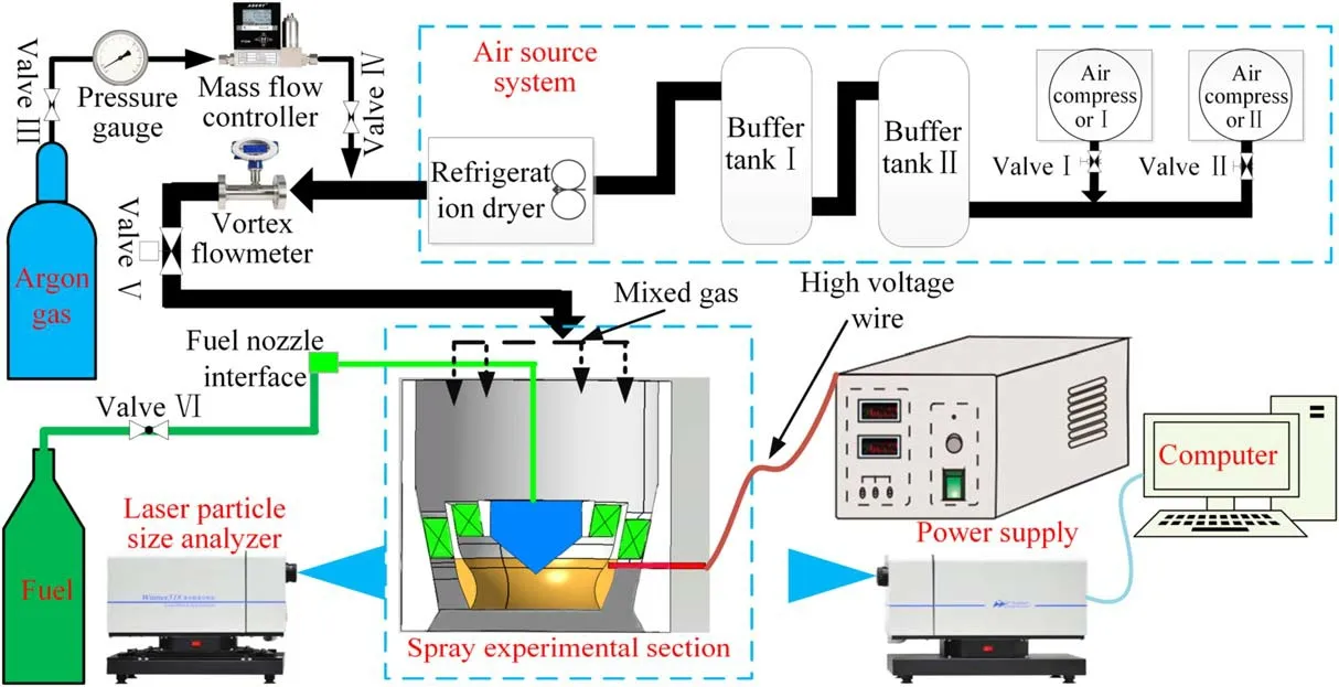
Figure 1.Schematic of the gliding arc experimental system.
The gliding arc plasma is excited using a plasma power supply system consisting of a low-temperature millisecond pulse power supply (CTP-2000K, Nanjing Suman Plasma Technology Co.) and a voltage regulator.The power supply changes the output voltage of the voltage regulator into a high-voltage sinusoidal AC signal.The input of the power supply is 220 V, the modulation voltage is 0-250 V, the output voltage peak of the power supply is 0-30 kV, and the power supply frequency is 1-100 kHz with a power of 500 W.
The air supply system is composed of a screw air compressor (BK132-8, displacement 24 m3min-1, nominal exhaust pressure 0.8 MPa), pressure storage tank (volume of 4 m3), cold and dry machine (LY-D200ah, 28.5 m3min-1),inner cone flowmeter (DYNZ16-8001E12), intelligent flow integrator, and other components.Thus, the system can accurately measure the volumetric airflow.
2.2.Measurement system
The measurement system consists of a Winner318 spray laser particle size analyzer and a CNC 3D coordinate displacement mechanism.The Winner318 spray laser particle size analyzer is installed on the cantilever claw end of the 3D coordinate displacement mechanism, and its movement trajectory is controlled with a software program.This completes the particle size measurements for the entire spray area.
The Winner318 spray laser particle size analyzer consists of a host with an optical system and a signal acquisition and processing system.The optical system is composed of a Nd:YAG laser with a power of 40 mW and wavelength of 532 nm, along with a collimating lens.The host is connected to a computer as a display to output the experimental data.The laser beam is filtered, expanded, filtered, collimated, and then irradiated onto the test area.The particles to be measured in the test area scatter the incident laser irradiation.The intensity and spatial distribution of the scattered spectrum are related to the size and distribution of the measured particle group.After converging again through the lens, the scattered light is received by a photoelectric array detector located on the rear focal plane of the lens.After being converted into an electrical signal, it is amplified, digitized, and sent to the computer through the communication port.After inversion and data processing, the volume distribution curve, characteristic particle size, and Sauter average particle size of the measured particle group are output.The adjustable measuring range of the equipment is 15-711 μm,the sampling frequency is 3 Hz, and the device has a 3D fine-tuning detection unit.Multiple automatic scattering correction functions are designed based on the spray concentration, which gives accuracy and repeatability errors of less than 3%.The instrument can capture continuous dynamic testing of the samples.
In the spray experiments, a high-speed CCD camera(Mini UX50), high-voltage probe (Tektronix P6015A),current probe (Tektronix TCP0030), and oscilloscope (Tektronix DPO4104B) were used to collect the arc motion characteristics and voltage and current signals from the gliding arc discharge.The frame rate of the high-speed CCD camera was set to 10 000 fps and the exposure time was 100 μs,which quickly captures the motion of the gliding arc.
2.3.Gliding arc plasma fuel atomizing excitation
A gliding arc plasma fuel atomization exciter was designed to promote the application of gliding arc plasma-enhanced combustion technology in aeroengines and improve fuel atomization quality using gliding arc plasma[15].The design combines the gliding arc plasma actuator with the dome of the aeroengine combustion chamber and uses the rotating airflow at the combustion chamber dome to drive the arc movement.A schematic is shown in figure 2.The three-dimensional rotating gliding arc exciter is composed primarily of a cathode fuel nozzle,anode Venturi tube,cyclone,and bell mouth.The minimum breakdown distance between the cathode fuel nozzle and anode Venturi tube is 10.9 mm, and the outlet angle of the anode venturi tube is 37°.The anode Venturi tube is connected to the high-voltage alternating current through a high-voltage cable, and the cathode fuel nozzle and combustion chamber are grounded together.The anode Venturi tube and cathode fuel nozzle generate a plasma arc under the excitation of a strong electric field to form a three-dimensional rotating gliding arc plasma discharge under the action of rotating airflow in the cyclone.The fuel jet from the cathode fuel nozzle passes through the gliding arc discharge area, further promoting fuel atomization.
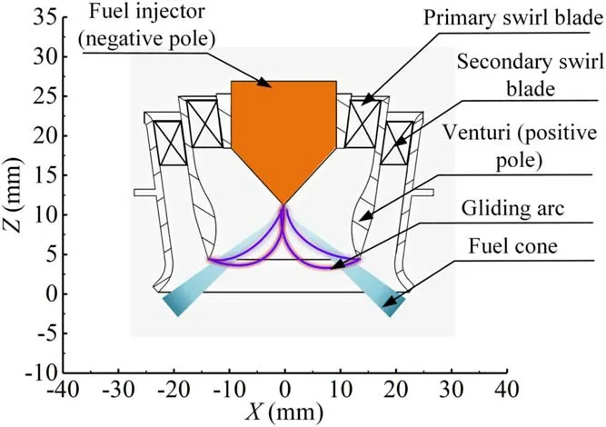
Figure 2.Schematic of the gliding arc plasma fuel atomization actuator.
2.4.Experimental conditions
The experimental conditions are shown in table 1.Aviation kerosene (RP-3) was selected as the fuel during the experiment.Three-way valves were used to connect the air source system,argon system,and spray laboratory module to ensure that the plasma arc did not ignite the fuel after atomization in the experimental section.The mass flow controller was used to detect the makeup amount of argon, and the vortex flowmeter was used to detect the total airflow into the experimental section.As long as the argon flow is 1/3 of the total gas flow, the proportion of argon replenishment can be guaranteed.The added argon enters the experimental section together with the airflow of the gas supply system to protect and prevent combustion.All experiments were measured under the conditions of stable air and fuel flows.

Table 1.Experimental conditions.
2.5.Operating characteristics of gliding arc plasma fuel atomizing exciter
A high-speed camera recorded the sliding of the plasma arc along the Venturi tube under atmospheric pressure, as shown in figure 3.The gliding arc plasma discharge was driven by a rotating airflow of 20 m3h-1.The movement of the gliding arc plasma was captured under breakdown, tensile sliding,and extinction.Among them,figures 3(a)and(l)show the arc breakdown moment, and figures 3(b)-(k) are images of the arc movement and extension process.The arc first breaks down at the minimum distance between the two electrodes under the excitation of a high-voltage electric field.Driven by the airflow, the arc stretches and twists while its root slides between the two poles.When the arc develops to a certain length, the voltage between the two electrodes cannot maintain the arc development and is extinguished.When the arc is extinguished, the active components in the arc channel are blown downstream by the rotating airflow.At this time, the condition of the forming arc channel downstream is better than the arc breakdown condition at the minimum spacing.Therefore, the arc does not necessarily continue to break down at the minimum distance, and the arc breakdown location becomes random.According to figures 3(a) and (l),when the arc enters the subsequent development cycle, the breakdown position of the arc differs.
The voltage and current signals in the gliding arc discharge process, as collected synchronously with the arc movement from figure 3,are shown in figure 4.Time t0is the arc breakdown moment at which the voltage has a pulse peak of approximately 5 kV and the instantaneous current reaches about 15 A.The arc shape corresponds to figure 3(a), where the arc has higher brightness and a shorter length.After arc breakdown, the voltage and current develop a sinusoidal pattern, and the voltage increases with arc stretching.Once the arc develops to a certain length (arc length shown in figures 3(h)-(k)),the voltage and current have repeated pulse peaks(as shown in the voltage and current waveforms within the period from t2to t3in figure 4).This is because the arc stretching increases the channel resistance,and the stability of the current is not sufficient to maintain its development,which causes it to dissipate.However,the conditions to form the arc channel are optimal, and a peak voltage and current pulse appear to maintain arc stretching.When the power supply is insufficient to maintain continuous development of the arc, it extinguishes, and a new arc channel is formed.As illustrated by t4in figures 3(l) and 4, a new arc channel is formed, and the arc movement enters the next cycle.
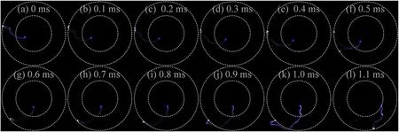
Figure 3.Arc sliding process over time.
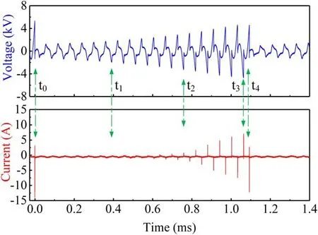
Figure 4.Gliding arc discharge voltage and current.

Figure 5.Gliding arc discharge power.

Figure 6.Distribution structure of the spray field.(a)Cloud diagram of the spray field distribution, (b) particle size distribution on the radial section.
Figure 5 shows variations in the discharge power for the gliding arc discharge process.The analysis shows that the gliding arc discharge power first increases and then decreases with the inlet airflow.However, under a 120 V modulation voltage, the gliding arc discharge power increases with the inlet airflow, and the trend of an initial increase followed by a decrease appears in some areas.However, within the airflow range involved in the spray experiments (15, 20, and 25 m3h-1), an increased airflow also increases the discharge power of the gliding arc because a greater gas flow alters the discharge mode of the gliding arc [23].This enhances both the local turbulence degree and the heat and mass transfer between the plasma arc and the environment.Therefore, more energy is needed to develop the plasma arc further.With a greater modulation voltage from the power supply, the discharge power increases significantly because the energy input from the power supply to the two electrodes increases with the modulation voltage, which enhances the discharge power.
3.Results and discussion
3.1.Analysis of macroscopic characteristics of the spray field
The distribution structure of the fuel spray field is shown in figure 6 for a 0.45 g s-1fuel supply flow and no swirling airassisted atomization.Figure 6(a) indicates that the fuel spray field is cone-shaped, and the overall particle size distribution ranges from 30 to 130 μm.The fuel particle size is larger within the spray cone angle and has a concentrated distribution.In figure 6(a),the blue area represents fuel particle sizes less than 40 μm and is defined as outside the fuel spray cone angle as marked with the black dotted line,which is only used for the macroscopic description of particle size distribution.Figure 6(b) shows that the particle size distribution curves along different axial sections have symmetric concave distributions.The local minimum of the fuel particle size is at the center point, and the curve becomes steeper toward the fuel nozzle.This result agrees with the distribution law of the fuel particle size in the spray field structure.
The influence of the fuel supply flow change on the fuel particle size distribution is considered when there is no airassisted atomization,as shown in figure 7.The Wfin the figure represents the fuel supply flow, Δ is the fuel spray non-uniformity coefficient, given by Δ = (SMDmax-SMDave) /SMDave[17], and smaller values indicate a more uniform fuel spray.With a smaller fuel flow, the fuel particle size increases in the mainstream spray area (red area in figure 6(a)), mainly because the fuel supply flow decreases, and the fuel supply pressure in front of the nozzle decreases.Thus, the fuel supply pressure decreases, the kinetic energy of the injected fuel decreases, the friction and shear between the fuel and air after leaving the nozzle decreases,and the fuel particle size increases.In the range of Z=-10 to -30 mm, the fuel spray nonuniformity coefficient increases for smaller fuel supply flows,which is primarily the result of the increased fuel particle size.In the Z=-40 to-60 mm range, the fuel supply flow decreases, but the spray nonuniformity coefficient also decreases.Combined with the fuel particle size distribution curve,this is mainly due to smaller fluctuations in the particle size, even though the particle size is still large.
The influence of the airflow on the fuel particle size distribution when the fuel supply flow is 0.57 g s-1is shown in figure 8.The Wain the figure represents the airflow.The increased gas flow reduces the particle size of the fuel droplets and improves the uniformity of the spray field, especially in the spray cone angle.This is because the fuel ejected from the nozzle forms a mixture of fuel and gas under the action of air.The air in the mixture expands rapidly under the disturbance of high-speed airflow [6], which accelerates the atomization of the fuel droplets.Figures 7(a)and(b)show that after air is injected, the fuel particle size curve becomes convex instead of concave within the cone angle of the fuel spray.The absolute maximum fuel particle size appears at the center point, X=0 mm.
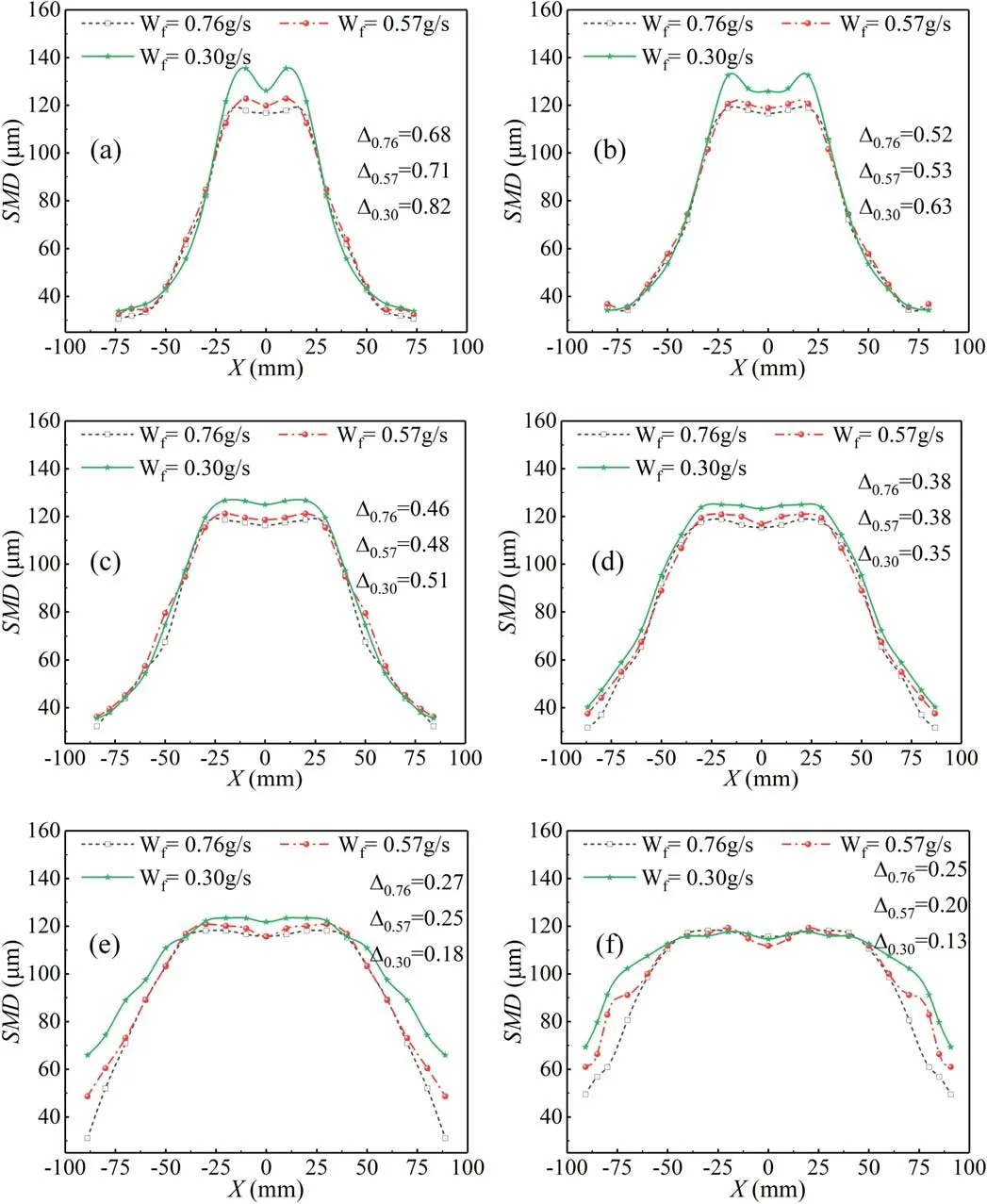
Figure 7.Effects of fuel flow on the fuel particle size distribution.(a)Z=-10 mm,(b)Z=-20 mm,(c)Z=-30 mm,(d)Z=-40 mm,(e) Z=-50 mm, (f) Z=-60 mm.
After air is introduced,the local minimum particle size of fuel is formed at X=-20 mm and 20 mm.This is because an annular vortex is formed downstream after the air passes through the swirler; a schematic of the ‘vortex structure’ is shown in figure 8(g)[17].The inner region of the red ellipsis of the vortex center in figure 8(g) is defined as the vortex core, where the left side of the vortex core is defined as the outer side of the vortex,and the right side of the vortex core is defined as the inner side of the vortex.The inner side of the vortex is a low-pressure area where the airflow velocity is small.The fuel droplets on the outer side of the vortex are brought to the inner side of the vortex; thus, the absolute maximum fuel particle size appears on the inner side of the vortex.However, at the vortex core, the streamlines are relatively sparse, and the fuel molecules are affected by the airflow trajectory,which forms the local minimum of the fuel particle size.

Figure 8.Effect of airflow on the fuel particle size distribution.(a) Z=-10 mm, (b) Z=-20 mm, (c) Z=-30 mm, (d) Z=-40 mm,(e) Z=-50 mm, (f) Z=-60 mm, (g) schematic of vortex [17].

Figure 9.Effect of the modulation voltage on the fuel particle size distribution.(a) Z=-10 mm, (b) Z=-20 mm, (c) Z=-30 mm,(d) Z=-40 mm, (e) Z=-50 mm, (f) Z=-60 mm.
The influence of the fuel supply flow on the fuel particle size distribution is shown in figure 9 after coupling between the air and gliding arc discharge(airflow is 20 m3h-1and the power supply modulation voltage is 200 V).Within the cone angle of the fuel spray,the fuel supply decreases,the particle size of the fuel droplets increases, and the uniformity of the spray field deteriorates.This is because when the temperature and pressure fields at the outlet of the fuel nozzle are relatively constant, the fuel supply reduces, the pressure difference before the fuel nozzle becomes smaller, there is less kinetic energy for the injected fuel, and the aerodynamic effect between the fuel and air is relatively weak.In addition, as the fuel supply flow is reduced,the proportion of the breakdown mode in the discharge mode of the gliding arc decreases, which leads to a lower discharge power for the gliding arc[23].This weakens the ability of the gliding arc to process the fuel, deteriorating the fuel atomization quality.Most droplets outside the cone angle of the fuel spray escape in the mainstream spray area, and its change law differs from the above law.Figures 8(b)-(f) show that the fuel spray inhomogeneity coefficient does not increase with a lower fuel supply flow but achieves a global minimum of 0.57 g s-1.However, the particle size distribution curve indicates that the particle size global minimum is at 0.76 g s-1.This maximizes the gliding arc discharge mode of the breakdown mode when the fuel supply flow rate reaches the absolute maximum, which increases the local turbulence (gliding arc discharge produces local disturbances to the discharge area)[24].The aerodynamic factors increase the local nonuniformity of the spray.
3.2.Droplet size-frequency distribution
The particle size of the fuel spray is an important factor that affects the fuel evaporation rate.The droplet size-frequency distribution is used to analyze the particle size of the fuel spray and quantitatively describe the influence of the gliding arc plasma discharge on the particle size distribution.The droplet size-frequency distribution is given byφB/Δd[25],whereφBis the volume fraction in each size interval andΔdis the size interval.
Applying the above formula provides the droplet sizefrequency distribution shown in figure 10 when the fuel supply flow is 0.57 g s-1,and the inlet airflows are 0,20,and 25 m3h-1.The ‘w/o plasma’ labels in the figure indicate plasma excitation without the gliding arc.The droplet size frequency presents a biased normal distribution.When the inlet airflow is 0 m3h-1, most droplets are distributed between 90 and 130 μm,and the 110-120 μm range accounts for the largest proportion at 4.41%μm-1.After swirling air is introduced (20 m3h-1), the fuel injected from the nozzle forms a fuel-gas mixture, and the air expands rapidly under the disturbance of the high-speed airflow, which accelerates the fuel droplet breakage.The inlet airflow increases,and the spray field of the aerodynamic force is enhanced.The shear force between the fuel droplets and air friction increases,accelerating fuel droplet fragmentation.Therefore, the proportion of the droplet frequency over 120-130 μm decreases,and the absolute maximum droplet frequency proportion tends to smaller particle sizes.When the inlet airflow increases to 25 m3h-1, the absolute maximum droplet sizefrequency ratio is reduced to 3.03% μm-1with a range of 100-110 μm.
The influence of the gliding arc plasma on the droplet size-frequency distribution is shown in figure 11, where U0represents the modulation voltage.After the gliding arc plasma-assisted atomization is applied, the frequency proportion of the larger fuel particle sizes is reduced, and the peak value of the droplet size-frequency distribution curve moves toward smaller particle sizes.The working condition with an airflow of 20 m3h-1is taken as an example.Under non-gliding arc plasma-assisted atomization, the fuel particle size is concentrated in the 90-130 μm range,and the absolute maximum droplet size-frequency ratio appears in the 110-120 μm range.Droplets in the 120-130 μm range disappear after the gliding arc plasma-assisted atomization,and the absolute maximum droplet size-frequency ratio shifts to smaller particle sizes.The thermal effects generated during gliding arc plasma discharge instantly heat the discharge area[9, 10] and promote the atomization and evaporation of fuel droplets.At the same time,the gliding arc discharge enhances the eddy current intensity and air velocity downstream of the cyclone[24,26].This increases the interaction force between the fuel droplets and air, and promotes fuel atomization.Therefore,when the gliding arc plasma modulation voltage is 160 V,the fuel particle size is concentrated in the 70-120 μm range,the absolute maximum fuel droplet size-frequency ratio shifts to the 100-110 μm range, and the absolute maximum droplet size-frequency ratio decreases to 3.81% μm-1.

Figure 10.Effect of airflow on the droplet size-frequency distribution.
3.3.Cumulative droplet size distribution
The cumulative distribution curve of the droplet sizes is an important parameter to describe the droplet size distribution.Its expression is [25]
whereQrepresents the total volume fraction contained in droplets with sizes smaller than D,VDrepresents the total volume of droplets with sizes smaller than D, andVrepresents the volume of any droplet.
Figure 12 shows the cumulative distribution curves of the droplet sizes at different airflows with a fuel supply flow rate of 0.57 g s-1and power supply modulation voltage of 200 V.The airflow affects the slope and position of the cumulative droplet size distribution curve.A larger airflow gives a greater slope for the cumulative distribution curve,which produces a higher position.

Figure 11.Effect of gliding arc on the droplet size-frequency distribution.(a) Air flow is 20 m3 h-1, (b) air flow is 25 m3 h-1.

Figure 12.Effects of airflow on the cumulative distribution of the droplet sizes.
A larger curve slope gives a smaller absolute maximum value particle size.The higher the curve is, the larger the proportion of small fuel droplets.The analysis of section 3.1 shows that the aerodynamic force plays an important role in the fuel atomization process, and a larger airflow provides stronger interaction forces between the fuel droplets and air.The junction analysis of section 2.5 indicates that a larger airflow gives a higher gliding arc discharge power.Thus,the processing capacity of the gliding arc is greater,and the fuel atomization quality improves.
To explore the gliding arc discharge effect on the cumulative droplet size distribution, we calculate the cumulative droplet size distribution curve under different working conditions in figure 13.The red chain line represents no gliding arc plasma, the dotted blue line represents a modulation voltage of 160 V,and the solid green line represents a power modulation voltage of 200 V.With increased plasma modulation voltage, the cumulative droplet size distribution curve shifts upward,and its slope increases.That is to say,the absolute maximum particle of fuel particle size becomes smaller as the supply modulation voltage increases.Figure 13(c)indicates that when the airflow is 20 m3h-1and the fuel supply flow is 0.57 g s-1,the cumulative droplet size distribution curve reaches its peak at 122.59 μm without gliding arc plasma excitation.When the gliding arc plasma modulation voltage is 200 V, the position where the cumulative droplet size distribution curve reaches a peak shifts to 111.66 μm,and the absolute maximum droplet size is reduced by 10.93 μm, proving that the gliding arc plasma excitation can effectively reduce the fuel particle size.
D0.5represents the droplet size when Q is 50%, which characterizes the median diameter; a smaller value gives a higher spray uniformity.Its value decreases with the modulation voltage, indicating that the droplet’s overall atomization effect is improved.The D0.5value is 109.01 μm when there is no gliding arc plasma excitation and 100.951 μm when the gliding arc plasma modulation voltage is 200 V.This indicates that the atomization effect of the spray field improves after applying the gliding arc plasma.When the gliding arc discharges, it instantly increases the temperature of the discharge area to thousands of Kelvin, which directly impacts the viscous force between the fuel molecules and surface tension.Thus, the fuel droplets more easily atomize and evaporate.In addition, the gliding arc discharge process results in high local pressure in its vicinity,which causes local turbulence pulsation and accelerates the fuel droplet breakdown.Thus, the fuel atomization quality is improved.
Compared with figures 13(b)-(e), the slope of the cumulative distribution curve of droplet size decreases, and the value of D0.5increases when the fuel supply flow decreases.This means that a smaller fuel flow gives a larger maximum fuel particle size and worsens the atomization uniformity.Without gliding arc plasma excitation, the value of D0.5is 103.76 μm when the flow rate is 0.76 g s-1, and D0.5is 111.49 μm when the flow rate decreases to 0.3 g s-1.When the outside conditions are the same as the inlet airflow phase,the temperature and pressure fields at the nozzle outlet are constant,the fuel supply flow decreases,the pressure drop in front of the fuel nozzle decreases,the kinetic energy of the injected fuel is small, and the interaction force between fuel and air decreases.The fuel supply quantity is small, the gliding arc discharge power decreases,and the gliding arc on the fuel atomization effect is abated.Thus, the fuel atomization quality deteriorates.

Figure 13.Cumulative droplet size distribution for various working conditions.(a)Wa=15 m3 h-1,Wf=0.34 g s-1,(b)Wa=20 m3 h-1,Wf=0.76 g s-1, (c) Wa=20 m3 h-1, Wf=0.57 g s-1, (d) Wa=20 m3 h-1, Wf=0.45 g s-1, (e) Wa=20 m3 h-1, Wf=0.30 g s-1,(f) Wa=25 m3 h-1, Wf=0.57 g s-1.
3.4.Average particle size and change of representative particle size
The effects of gliding arc plasma discharge on the representative particle size (D0.5, D0.9) and average particle size (D32) of the fuel spray were studied for an airflow of 20 m3h-1.D0.9represents the droplet size when Q is 90%and characterizes the upper 10% of droplet sizes; the larger the value indicates, the more the number of large-sized droplets.D32is the average particle size,which represents the Sauter mean diameter(SMD)of the droplets.Figure 14(a) shows the variations in D0.5, representing the spray uniformity.Figure 14(b)shows the variations in average particle size, and figure 14(c) shows variations in D0.9.Applying the gliding arc plasma excitation decreases the trend of the average fuel spray particle size and representative particle size(D0.5and D0.9).This decreasing trend becomes more evident when the modulation voltage of the gliding arc plasma is increased.When the fuel flow rate is 0.76 g s-1, the average particle size of fuel droplets without the gliding arc plasma excitation is 93.55 μm.The average fuel droplet particle size is 89.69 μm when the gliding arc plasma modulation voltage is 200 V,which is a reduction of 4.1%.D0.5decreases from 103.76 to 98.91 μm, a reduction of 4.7%, and D0.9decreases from 113.21 to 105.81 μm, a reduction of 6.5%.These results show that the gliding arc discharge has significant advantages in decreasing the average particle size of the fuel spray, which decreases the absolute maximum fuel droplet size and improves the fuel spray uniformity.This is because the ‘aerodynamic effect’produced in the gliding arc discharge process increases the flow field turbulence and accelerates fuel droplet fragmentation.At the same time, the ‘temperature rise effect’ produced in the gliding arc discharge process promotes fuel droplet atomization and evaporation.

Figure 14.Effect of gliding arc plasma discharge on the mean and representative particle sizes.(a) D0.5, (b) D32, (c) D0.9.
The D0.5, D0.9, and average particle size of the fuel spray tend to increase for smaller fuel flow rates.When applying the gliding arc plasma,the particle size decreases significantly at 0.76 and 0.57 g s-1compared with 0.30 g s-1.For D0.9,a fuel supply of 0.30 g s-1reduces the particle size by 6.3%after applying the gliding arc plasma excitation, and fuel supplies of 0.76 and 0.57 g s-1give 9.1% and 6.5% reductions, respectively.For the average particle size, when the fuel supplies are 0.76, 0.57, and 0.30 g s-1, the reductions are 4.3%, 4.1%, and 3.6%, respectively.There are two reasons for this.On one hand, the fuel supply flow and front nozzle pressure decrease, and the preliminary atomization effect worsens.On the other hand, the decreased fuel supply reduces the proportion of the breakdown mode in the gliding arc discharge process, and the discharge energy in the breakdown mode is greater than that in the stable sliding mode[23].Thus,the fuel supply volume is reduced.The power of the gliding arc discharge process decreases, so the processing capacity decreases,and the fuel particle size increases.
4.Conclusions
A gliding arc plasma fuel atomization exciter was proposed to improve the fuel atomization quality in the dome of an aeroengine combustor.The structure of the spray field was analyzed using laser particle size analysis.The effects of the airflow,fuel supply, and plasma excitation on the fuel particle size distribution were studied.The main conclusions are as follows:
(1) Under the excitation of a strong electric field, a 3D gliding arc discharge was formed between the fuel nozzle and Venturi,and the discharge power of the gliding arc increased with the modulation voltage.When the modulation voltage was 160 and 200 V, the gliding arc discharge power first increased and then decreased with the gas flow.
(2) The temperature rise and pneumatic effect from the gliding arc discharge accelerated the crushing, atomization, and vaporization of fuel droplets, while the average and representative particle sizes of fuel droplets were reduced.Thus, the cumulative droplet size distribution curve slope increased, the small droplet size proportion increased, and the atomization effect improved significantly.Compared with the working condition of plasma-assisted atomization without a gliding arc, when the modulation voltage of the gliding arc power supply was 200 V, the D0.5, D0.9, and average particle sizes of the fuel droplets were reduced by 4.7%, 6.5%, and 4.1%, respectively.
(3) The increased airflow not only changed the structure and enhanced the aerodynamic action of the spray field but also increased the power of the gliding arc discharge, which improved the fuel atomization effect.The fuel supply flow decreased and reduced the injection pressure in front of the nozzle, worsening the fuel atomization effect.At the same time,reduced fuel flow also affected the discharge mode of the gliding arc, reduced its discharge power, worsened the fuel atomization effect,and increased the particle size of fuel atomization.When the modulation voltage was 160 V, the D0.9,D0.5,and average particle sizes at a fuel supply flow of 0.30 g s-1increased by 3.6%,4.7%,and 4.9%,respectively,compared with a fuel supply flow of 0.76 g s-1.
Acknowledgments
This work was supported by National Natural Science Foundation of China (Nos.91741112 and 52276142).
猜你喜欢
Chinese Physics B(2023年2期)2023-03-13
中国民间疗法(2021年19期)2021-11-20
Chinese Physics B(2021年6期)2021-06-26
北极光(2020年1期)2020-07-24
北方文学(2018年2期)2018-01-27
幸福(2016年6期)2016-12-01
车迷(2015年6期)2015-03-20
传奇·传记文学选刊(2014年8期)2014-10-30
中医研究(2014年8期)2014-03-11
 Plasma Science and Technology2023年3期
- Plasma Science and Technology的其它文章
- Relativistic toroidal light solitons in plasma
- Valley-dependent topological edge states in plasma photonic crystals
- Bulk moduli of two-dimensional Yukawa solids and liquids obtained from periodic compressions
- Modeling of magnetized collisional plasma sheath with nonextensive electron distribution and ionization source
- Observation of the poloidally asymmetrical density perturbation of sawtooth collapse on J-TEXT
- Alfvén continuum in the presence of a magnetic island in a cylinder configuration