
Ignition dynamics of radio frequency discharge in atmospheric pressure cascade glow discharge
2023-03-13 09:19:20YaRongZhang张亚容QianHanHan韩乾翰JunLinFang方骏林YingGuo郭颖andJianJunShi石建军
Chinese Physics B 2023年2期
关键词:建军
Ya-Rong Zhang(张亚容) Qian-Han Han(韩乾翰) Jun-Lin Fang(方骏林)Ying Guo(郭颖) and Jian-Jun Shi(石建军)
1College of Science,Donghua University,Shanghai 201620,China
2Textile Key Laboratory for Advanced Plasma Technology and Application,Donghua University,Shanghai 201620,China
Keywords: pulsed voltage modulated radio frequency,radio frequency(RF)discharge burst,residual plasma species
1.Introduction
Radio frequency (RF) atmospheric pressure glow discharges (APGD) have higher plasma density, undergo lower breakdown and can maintain voltage compared to those in atmospheric dielectric barrier discharges (DBD) excited by power in the kHz range.[1]In particular, they can generate a large area of uniform plasmas,and the associated devices are simple and easy to control.Therefore, they can be applied to surface modification,[2-4]biomedical applications,[5-7]and deposition.[8-10]The RF APGD can provide high plasma density at a low RF voltage without dielectric barriers,[11-13]but their high power consumption and gas temperature induce their instability, which restricts their applications, especially in the processing of thermally sensitive materials.[14]Pulsemodulated(PM)RF APGDs were proposed to reduce the discharge power consumption and improve the discharge stability, in a system in which the dynamics and characteristics of the RF discharge burst could be manipulated by switching the RF power on and off alternatively.[15,16]The fact that, in PMRF discharges,residual electrons from the previous RF discharge have an auxiliary effect on the next pulse-modulated RF discharge has been investigated.[17]The injection of a pulsed discharge into a continuous RF discharge in a plasma jet experiment was explored, and successfully increased the intensity of the RF discharge.[18]To improve the efficiency of plasma applications, the characteristics of the pulsed-voltage modulated RF need to be thoroughly investigated.
It was found that the pulsed-voltage modulated RF effect can be manipulated by the time interval between the pulse voltage and the RF discharge bursts.In this paper,the fact that the pulse-assisted radio frequency mechanism can be controlled by the time interval (t) between radio frequency discharge bursts is studied.Experiments on the discharge characteristics of current-voltage waveforms and the temporal and spatial evolution of light emission illustrate the dynamics of the interaction between the pulsed discharge and radio frequency discharge burst.
2.Experimental setup
Figure 1 shows the experimental setup.The atmospheric pulse modulated RF glow discharge occurs between two parallel plate electrodes.The parallel plate electrode has a circular stainless steel electrode with a diameter of 20 mm and a fixed gap distance of 2.4 mm.The two electrodes are fixed with a ceramic sheet with a thickness of 0.8 mm and a relative dielectric constant of 9,which is enclosed in a glass box.The pressure and flow of helium(99.999%)are 760 Torr and 2.5 slm, respectively.Using the first signal generator (Tektronix AFG 3102) to generate two synchronized 5 kHz pulse signals,the first pulse signal(5 kHz duty cycle 0.5%)is used to control the pulsed discharge system and the enhanced charge coupled device(ICCD)camera(Andor i-Star DH734).In the current work,the sinusoidal radio frequency signal(12 MHz)is generated and modulated by a pulse signal (5 kHz) with a duty cycle of 50%.A pulse signal (5 kHz) with a duty cycle of 0.5%is generated by another waveform generator(Tektronix AFG 3102), which is synchronized with the pulse signal from the previous waveform generator.The discharge current and applied voltage are measured by a broadband current probe (Pearson 2877) and a broadband voltage probe(Tektronix P5100), respectively, which are used to trigger a high-voltage pulse generator (DEI PVX-4110) powered by a DC high-voltage generator(SPELLMAN SL1200).Then,the high-voltage pulse obtained from the pulse generator is transmitted to the upper electrode.A digital storage oscilloscope(Tektronix DPO 4101) is used to record the applied voltage and current waveforms.The emission spectrum is measured using a spectrometer (Andor Shamrock, focal length 0.3 m,grating 600 grooves/mm).
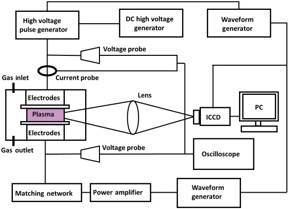
Fig.1.A schematic diagram of the experimental system.
3.Results and discussion
Figures 2 and 3 show the voltage and current waveforms of the pulse-modulated RF cascade discharge and RF discharge.The pulse voltage and RF voltage are applied at 0µs and 6µs,with amplitudes of 1200 V and 300 V,respectively.The time interval between the pulse falling edge voltage and the RF voltage is Δt=5 µs.In Fig.2(b), there are two discharges that ignite at 0.2 µs and 1.24 µs, respectively, corresponding to the rising and falling phases of the pulse voltage;the peak value is about 0.42 A and 0.5 A,which is consistent with that of dielectric barrier pulsed discharges.[19,20]Detailed waveforms of the ignition voltage and current when the discharge is about 6µs are shown in Fig.3,which are similar to the RF APGD without pulse discharge assistance.[21-24]The RF voltage starts to rise at 6µs and reaches a stable amplitude of about 400 V at 7.6µs,which indicates that the duration of the rising phase of the RF voltage is about 1.6 µs.The discharge current also shows an ignition phase of about 1.5 µs and, as the current amplitude increases, it reaches an amplitude of about 98 mA.This indicates that the high-voltage pulse produces a stronger discharge than the radio frequency power.
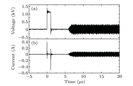
Fig.2.Waveforms of(a)the voltage and(b)current of the pulsed discharge and PM RF APGDs.
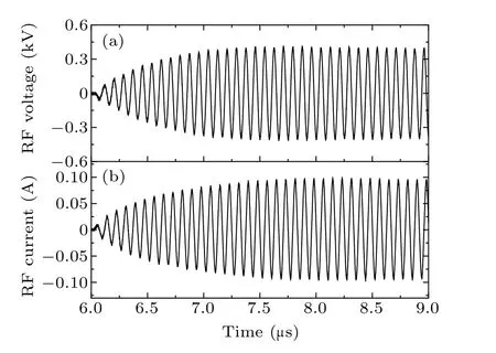
Fig.3.Waveforms of(a)RF voltage and(b)RF current during the RF discharge ignition phase.
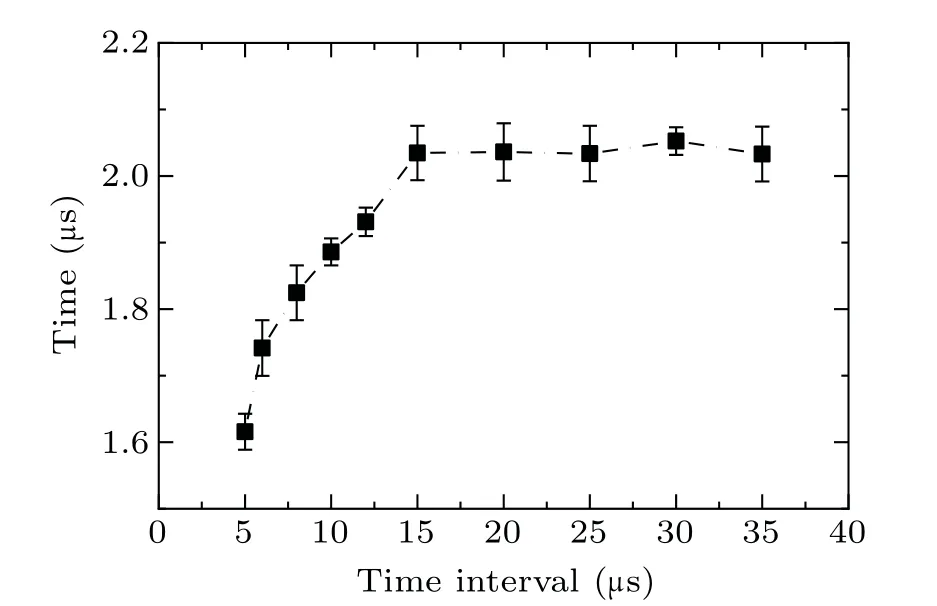
Fig.4.The ignition time of the RF discharge burst as a function of t.
Figure 4 shows the variation of the RF ignition time with the time interval Δtbetween the pulse and the RF voltage.The ignition time of the radio frequency discharge can be estimated by the discharge characteristics reaching the stable state,such as the discharge current amplitude, and the formation of a double-hump spatial discharge profile with two sheath regions above the electrode.When the time interval is 5 µs, 10 µs,15µs,and 20µs,the time required for RF ignition is 1.6µs,1.88 µs, 2.0 µs, and 2.0 µs, respectively: that is, as the time interval increases, the ignition time of the RF will increase.However, when the time interval exceeds 15 µs, the time of the RF ignition remains basically unchanged at 2µs, and the auxiliary effect of the pulse discharge on the ignition is no longer obvious.
Fig.5.Temporal evolution of the discharge spatial profile during the RF discharge ignition phase with Δt of(a)5µs,(b)10µs,and(c)20µs.
Figure 5 shows the normalized spatiotemporal evolution of the RF discharge with time intervals between the pulse discharge and RF discharge of 5 µs, 10 µs, and 20 µs, respectively.The normalization process is used to sum the discharge image intensity data along the electrode direction, normalize the summed data and arrange the data according to time, and finally obtain the spatial distribution along the electrode spacing direction.The radio frequency electrode is at 0 mm, and the pulse electrode is at 2.5 mm.The normalized spatial distribution of the discharge in Fig.5(a) corresponds to that in Fig.2.that shows the voltage and current waveforms.Here,the exposure time and the time interval between two consecutive images are both set to 10 ns.At 6µs,the radio frequency is ignited on one side, and then is gradually uniformly discharged on both sides.A bimodal structure is formed at 7µs.In Fig.5(c), the radio frequency is ignited from the middle at 21µs and uniformly discharged to form a stacked bimodal structure at 23 µs.It can also be explained by the residual plasma species from the previous pulsed discharge,which are trapped by the oscillation of the RF electrical field.[25]When the time delay grows to 22.0 µs, the hump of the discharge spatial profile expands in the discharge gap, which suggests enhancement of the sheath region above both electrodes.The double-hump spatial profile of the RF discharge burst is established completely when the time delay reaches 23.0 µs,from which the ignition time of the RF discharge burst can be estimated to be 2.0µs(21.0µs-23.0µs),which is shorter than that of a pulse-modulated RF APGD without a pulsed discharge.[19]In Fig.5(b), the radio frequency ignition form is between the previous two.With the increase in thettime interval, the radio frequency ignition time increases, and the sparking form gradually shrinks from a bimodal structure to a bell-shaped structure.
Figure 6 shows the intensity of the RF ignition discharge with pulse and RF voltage time intervals of 5 µs, 10 µs, and 20 µs, respectively.It is found that when the time interval is 5 µs, the time required for RF ignition is the shortest.With the assistance of the pulsed discharge, the ignition of the RF discharge is enhanced by reducing the discharge ignition time and improving the discharge intensity.
Fig.6.The image intensity of the RF discharge burst during the ignition phase with different t.
A spectrometer was used to collect the emission spectrum of the pulsed cascade radio frequency discharge plasma at the discharge gap,and the results are shown in Fig.7(a).The exposure time for spectrum shooting is 100 ms.The main spectral lines appearing in the discharge area are a OH spectral line(309 nm),a N2spectral line(281 nm-497 nm),an O spectral line(394 nm and 777 nm)and a He spectral line(706 nm).As the optical emission line at 706 nm is attributed to the transition of He(33S1→23P0,1,2), it is agreed that the intensity of the optical emission line at 706 nm (I706) is an indication of the presence of either electrons with energies above 2.9 eV or helium metastable and low-energy electrons.[26]The 706 nm line intensity mainly reflects the higher-energy electron density generated in the discharge.The change in the spectral line intensity at 706 nm in the initiation stage of the RF discharge with time reflects the initiation process of the discharge.It is shown in Fig.5(c)that the RF discharge ignites in the middle of the gas gap with a bell shape attof 20 ms.Before the discharge space sheath is formed, the higher-space electric field enables electrons to obtain higher energy, so the spectral line intensity is higher.With the formation of the discharge sheath structure,the discharge reaches a stable state,the electric field is concentrated in the sheath region, and the electric field in the discharge space decreases; therefore, the energy obtained by the electrons in the discharge space decreases,causing the intensity of the spectral lines to decrease and stabilize.In addition, with the decrease in the time interval, the maximum value of the spectral line intensity at 706 nm decreases,which also reflects the fact that there are more residual electrons in the discharge space,which contributes to the formation of the sheath structure and shortens the discharge ignition time.In addition,the spectral line intensity at 777 nm mainly indicates the active particles in the discharge ignition process,which is basically consistent with the changing trend of the spectral line intensity at 706 nm.

Fig.7.(a)The optical emission spectrum of the RF discharge and temporal evolution of optical emission intensity of(b)a helium line at 706 nm and(c)an oxygen line at 777 nm.
4.Conclusion
In summary,the pulse-modulated RF cascade discharges atmospheric-pressure helium, which enhances the radio frequency discharge by reducing the radio frequency ignition time.The results show that with the increase intfrom 5 µs to 20 µs, the ignition time of the radio frequency discharge burst increases from 1.6µs to 2.0µs,and the discharge space profile changes from a double-peak shape to a bell shape.The light emission intensity at 706 nm and 777 nm indicates that the assistance of the pulsed discharge in the ignition of the RF discharge depends on the number of residual plasma species.
Acknowledgment
Project supported by the National Natural Science Foundation of China(Grant Nos.11875104 and 12175036).
猜你喜欢
环球时报(2022-08-02)2022-08-02 22:41:57
Chinese Physics B(2022年6期)2022-06-29 08:52:52
Acta Mathematica Scientia(English Series)(2022年1期)2022-03-12 10:21:40
Plasma Science and Technology(2021年2期)2021-02-27 09:16:58
江苏教育·书法教育(2020年10期)2020-09-10 07:22:44
当代人(2020年4期)2020-05-08 08:18:04
中华魂(2017年8期)2017-11-22 12:21:09
绿色中国(2017年15期)2017-01-25 08:55:36
水动力学研究与进展 B辑(2015年3期)2015-02-16 06:50:29
外科研究与新技术(2012年1期)2012-08-15 00:54:32

- Chinese Physics B的其它文章
- Analysis of cut vertex in the control of complex networks
- Atlas of dynamic spectra of fast radio burst FRB 20201124A
- Investigating the characteristic delay time in the leader-follower behavior in children single-file movement
- Micro-mechanism study of the effect of Cd-free buffer layers ZnXO(X =Mg/Sn)on the performance of flexible Cu2ZnSn(S,Se)4 solar cell
- Thermally enhanced photoluminescence and temperature sensing properties of Sc2W3O12:Eu3+phosphors
- Heterogeneous hydration patterns of G-quadruplex DNA