Preparation of ZIF-8@PEBAX/PVDF nanocomposite membrane by the combination of self-assembly and in-situ growth for removing thiophene from the model gasoline
Zhesai Zhao, Qingwen Han, Wenwen He, Xiaolong Han,
1 School of Chemical Engineering, Northwest University, Xi’an 710069, China
2 Hubei Three Gorges Laboratory, Yichang 443007, China
3 School of Chemistry and Life Science, Advanced Institute of Materials Science, Changchun University of Technology, Changchun 130012, China
Keywords:Nanocomposite membrane ZIF-8 nanoparticles PEBAX Thiophene
ABSTRACT Metal-organic frameworks (MOFs) have gained attention in the development of MOFs/polymer hybrid membranes for pervaporation.However,the agglomeration of MOFs particles and interfacial defects limit its further application.In this study, we present a novel approach to fabricate a ZIF-8@PEBAX/PVDF nanocomposite membrane for removing thiophene from the model gasoline by combination of selfassembly and in-situ growth.Firstly, a PVDF supporting membrane was modified to have a negative charge.Next, positively charged zinc ions were attracted onto the negatively charged PVDF supporting membrane through electrostatic interaction.Afterwards, the Zinc ions deposited PVDF membrane was immersed into dimethylimidazole solution to form a uniform ZIF-8 layer.Finally, the ZIF-8 layer was coated with poly (ether-block-amide) (PEBAX) using the pouring method.Experimental results showed that the separating efficiency of the ZIF-8@PEBAX/PVDF nanocomposite membrane was improved significantly compared to that of pristine PEBAX membrane.The optimal permeation flux and enrichment factor of membrane were 27.80 kg·(m2·h)-1 and 6.9, respectively.
1.Introduction
In recent years, many countries have elevated the quality standards for gasoline products in response to the increasing environmental pollution.The sulfur compounds contained in gasoline are converted into SOxin combustion,which reduces the catalytic efficiency of automobile exhaust catalysts and releases noxious fumes into the atmosphere.Consequently, producing ultra-low sulfur gasoline has become a primary objective for refineries worldwide[1].In most cases, sulfur-containing fluid catalytic cracking (FCC)gasoline serves as the primary source of gasoline.To comply with increasingly stringent gasoline standards, FCC gasoline must undergo deep desulfurization [2].Currently, commonly used desulfurization methods include catalytic hydrodesulfurization[3],oxidative desulfurization[4],solvent extraction desulfurization[5],fixed bed adsorption desulfurization[6],biological desulfurization [7], alkylation desulfurization [8], pervaporation desulfurization, etc.Pervaporation technology is particularly promising for separating organic sulfur from gasoline due to its advanges of flexible operation, energy conservation, cost effectiveness and environmental friendliness [9].
It is critical to select a suitable membrane material to achieve effective separation performance in pervaporation separation processes.Currently, popular desulfurization membrane include poly(ether-block-amide) (PEBAX) [10], polyethylene glycol (PEG) [11],polydimethylsiloxane (PDMS) [12], polyimide (PI) [13], hydroxyethyl cellulose (HEC) [14], etc.According to the principle proposed by Lin [15], it is advisable to choose a polymer as the pervaporation desulfurization membrane,which solubility parameter is far from n-heptane’s solubility parameter but close to the solubility parameter of thiophene.Therefore, PEBAX is often selected as pervaporation desulfurization membrane due to its favorable solubility parameter [16].
Filling with inorganic filler is a popular method for enhancing the desulfurization performance of PEBAX membrane.While conventional inorganic fillers may not achieve desired separation performance due to the defects of interface [17].Compared with traditional inorganic porous materials, metal-organic frameworks(MOFs) have been increasingly used in organic-inorganic hybrid membranes because of their outstanding merits [18,19].Matzger et al.[20] obtained excellent adsorption materials for gasoline desulfurization using UMCM-150, Cu-BTC, MOF-177, MOF-5 and MOF-505, which was mainly attributed to the higher thiophene adsorption selectivity of these MOFs.However, excessive particle agglomeration is also a key problem for MOFs-polymer hybrid membrane,which to a large extent hinders the enhancing of membrane separation performance[21].To address this problem,many approaches have been developed in recent years.Jiang et al.[22]used Cu(II) loaded UiO-67-bpydc to enlarge the influence zone of the polymer-filler interface,thereby enhancing the desulfurization performance of PDMS mmebrane.Yang et al.[23]prepared an even ZIF-8 layer onto polyethyleneimine (PEI) supporting membrane using interfacial reaction in conjunction with self-assembly method, which had shown excellent separation performance.In a recent work, we prepared the ZIF-8@PEG/PVDF layer-by-layer(LBL)membrane,which greatly improved the desulfurizing capacity of the PEG membrane [24].However, the permeation flux was decreased significantly due to the introduction of the thicker ZIF-8 layer by the in-situ growth several times.Therefore,it’s necessary to explore new method to form thin layers of ZIF-8 on the supporting membrane to increase the permeation flux of the nanocomposite membrane.
In this study, a thin layer of ZIF-8 was formed on a PVDF supporting membrane using a self-assembly in conjunction with insitu growth method.Next, a PEBAX solution was poured onto the ZIF-8/PVDF membrane to prepare the ZIF-8@PEBAX/PVDF membrane.Detailed investigations were conducted on the surface chemical compositions, changes of function group and structures.Finally, the effects of in-situ growth time, temperature range and input concentration on the separation performance were researched specifically.
2.Experimental
2.1.Fabrication of membranes
2.1.1.Surface modification
Initially, the cleaned PVDF membrane was impregnated in 2.0 mol·L-1NaOH solution for 12 h at room temperature, causing the PVDF elimination reaction to generate double bonds.Subsequently,the NaOH pretreated membranes were directly immersed into an aqueous solution containing 10% (mass) acrylic and 1%(mass) initiator (K2S2O4) at 70 °C in a vacuum drying oven for 5 h.Afterwards,it was impregnated in deionized water for removing unreacted monomers.Through this step, the carboxyl groups were successfully grafted to the surface of PVDF membrane.
2.1.2.Preparation of ZIF-8@PEBAX/PVDF membrane
The procedure of preparing ZIF-8/PVDF membrane was similar to that described in the literature [23].The detailed process is as follows.(1) The carboxyl groups modified PVDF membrane was placed in a 2 mol·L-1sodium hydroxide solution under the condition of 65 °C for 1 h, and then rinsed to neutral with deionized water.(2) The hydrolytic PVDF membrane was placed in a Zn(NO3)2solution for 5 h (self-assembly process), and the resulting membranes were then rinsed with deionized water.(3) The selfassembled membrane was immersed in a dimethylimidazole solution and reacted with Zn2+for 0.5 to 2 h (in-situ growth process).Subsequently the resulting membrane was rinsed sequentially using ethanol and deionized water and then wiped with filter paper.
The procedure of preparation of PEBAX separation layer was as follows.In the first step, a 7% (mass) homogeneous solution of PEBAX 2533 was formed by dissolving it in n-butanol heated to 70 °C.Next, the mixed solution was poured onto the prepared ZIF-8/PVDF supporting membrane to obtain the ZIF-8@PEBAX/PVDF assembly membrane.The resulting membrane was then subjected to solvent removal by placing it in a natural environment and vacuum drying box in turn.Fig.1 illustrates the schematic of the ZIF-8@PEBAX/PVDF membrane fabrication process.

Fig.1.Schematic of preparing the ZIF-8@PEBAX/PVDF membrane.
2.2.Characterization and pervaporation test
The crystal degree,functional group,surface chemical composition and morphology are characterized by FTIR(Bruker,Germany),XRD (D8, Bruker, Germany), XPS (K-ALPHA, England) and SEM(ZEISS, Germany), respectively.The positron annihilation spectroscopy (PAS) was evaluated by a slow positron beam facility(Institute of High Energy Physics, China).Pervaporation desulfurization performance was evaluated using our self-made equipment[24].
3.Results and Discussion
3.1.Characterization
3.1.1.FT-IR
Fig.2 displays the FT-IR spectra of the PVDF membrane before and after surface modification.Compared to the original PVDF membrane, the spectrum of NaOH treated PVDF membrane(NaOH-PVDF) shows a slight peak of the C=C group at approximately 1645 cm-1[25].Upon grafting acrylic acid onto the surface(CH2=CHCOOH-PVDF), characteristic peaks of C=O and -OH appear at 1720 cm-1and 3500 cm-1respectively, indicating successful grafting of carboxyl groups onto the PVDF surface [26].After NaOH hydrolysis (CH2=CHCOO--PVDF), the peak at 1720 cm-1shifts to 1560 cm-1, and the -OH peak weakens, indicating successful formation of COO-group.Additionally, a peak of Zn—O appears around at 490 cm-1, coinciding with the characteristic peak of the C—F group of PVDF, which increases the intensity of the peak at 490 cm-1(CH2=CHCOOZn-PVDF).In the IR spectra of ZIF-8-PVDF membrane, no significant changes were observed because the characteristic peaks of C-N (1459 cm-1) and N—H(1340 cm-1)are too weak and C=N(1580 cm-1)is difficult to distinguish from the peak of COO-group at 1560 cm-1[27].

Fig.2.PVDF membrane’s FT-IR spectra before and after surface modification.
The prepared nanocomposite membrane’s FT-IR spectra are demonstrated in Fig.3.Compared to the pristine PVDF membrane,the characteristic peak of C=N appears at 1580 cm-1for all ZIF-8-PVDF membranes [28].Futhermore, the intensity of C-F group at 490 cm-1decrease as the in-situ growth time increases.For the 1.5 h-ZIF-8@PEBAX/PVDF membrane, new peaks appear at 2864 cm-1and 1740 cm-1, corresponding to the C-H bound and the C=O bound of PEBAX, respectively[29].These finding demonstrate that the PEBAX separation layer forms onto the ZIF-8 layer.
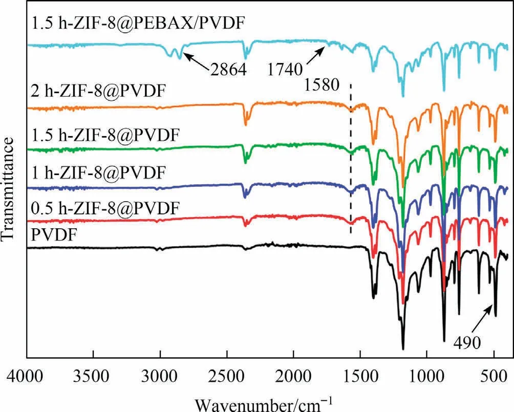
Fig.3.FT-IR spectra of the prepared membranes.
3.1.2.XRD patterns of membranes
As depicted in Fig.4, the crystal diffraction peaks at 17.72°,20.04°,22.8°and 25.98°represent the characteristic peaks of PVDF[30].Following the growth of ZIF-8 particles, new peaks of ZIF-8 appear at 7.3° and 12.7° in the spectra of ZIF-8/PVDF membranes[31].Moreover, as the in-situ grown time increases, the strength of these peaks also intensifies.After casting the PEBAX layer, the characteristic peaks of ZIF-8 particles become weaker than those of the ZIF-8/PVDF membrane.This observation suggests that the PEBAX layer has successfully covered the ZIF-8 layer.The characteristic peaks of PEBAX appear at approximately 20° [32], coinciding with the characteristic peak of PVDF, resulting in no notable changes in these peaks.
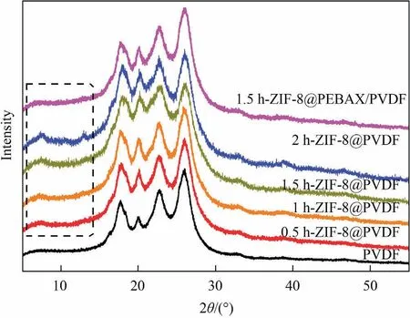
Fig.4.XRD pattern of the prepared nanocomposite membranes.
3.1.3.XPS spectra of membranes
As shown in Fig.5,the peaks of C 1s and F 1s correspond to the C and F elements of the PVDF.The weak peaks at 1022 eV, 1045 eV and 400 eV can be attributed to Zn 2p3/2,Zn 2p1/2and N 1s,respectively, indicating the formation of the ZIF-8 layer on the PVDF membrane surface.To investigate the impact of in-situ growth time, the high-resolution N 1s spectra are presented in Fig.5(b).It can be seen from the Fig.5(b)that the intensity of the N 1s spectra increases gradually with an extension of the in-situ growth time,indicating the formation of more ZIF-8 particles on the PVDF supporting membrane.Following the coating of the ZIF-8/PVDF membrane with a PEBAX solution,the Zn 2p3/2and Zn 2p1/2peaks disappear, and the intensity of O 1s peak increases.This observation confirms that a dense PEBAX layer has formed on the ZIF-8 layer.

Fig.5.XPS survey spectra (a) and high-resolution N 1s XPS spectra (b) of membranes.
Fig.6 shows the peaks of high-resolution C 1s spectra for unmodified PVDF, 1.5 h-ZIF-8/PVDF and 1.5 h-ZIF-8@PEBAX/PVDF.As illustrated in Fig.6(a), three peaks of C 1s appear at 284.8 eV, 286.21 eV and 290.65 eV, corresponding to the C-H,-CH2- and -CF2- groups of the PVDF molecular chain, respectively.As shown in Fig.6(b),the C 1s of 1.5 h-ZIF-8/PVDF exhibits new groups at 288.28 eV,285.23 eV and 291.19 eV,corresponding to the O=C-O bond of grafted acrylic acid, C-N bond and C=N bond of ZIF-8 particles, respectively [33].As depicted in Fig.6(c),the proportion of CH2, C-O, C=O and N-C=O are 57.84%,35.28%, 3.71% and 0.97%, respectively, which is consistent with the structure of PEBAX molecular chain.This finding further confirms that the ZIF-8/PVDF membrane has been fully covered by the PEBAX layer.

Fig.6.Comparison of high-resolution XPS C 1s spectrum for (a) unmodified PVDF, (b) 1.5 h-ZIF-8/PVDF and (c) 1.5 h-ZIF-8@PEBAX/PVDF.
3.1.4.SEM results of membranes
The surface images and mapping of the prepared membranes are surveyed by SEM.Fig.7(a1) shows the surface of the PVDF membrane,which has numerous micropores and is relatively even.As shown in Fig.7(a2)-(a5), the voids become fewer with the increase of in situ grown time from 0.5 h to 2 h,and the ZIF-8 layer becomes increasingly compact, nearly covering the entire membrane after a 2 h in-situ growth time.Fig.7(b1)-(b5) display the mapping diagrams of surface zinc, nitrogen and oxygen elements as the in-situ grown time increases from 0 h to 2 h, respectively.It is evident that with the increase of in-situ grown time, the density of zinc and nitrogen gradually increases, and the density of oxygen remains almost constant,indicating the formation of more ZIF-8 particles.Fig.7(c1)-(c5)demonstrates that the surface of the pristine PEBAX membrane and ZIF-8@PEBAX/PVDF membranes are smooth without any defects.
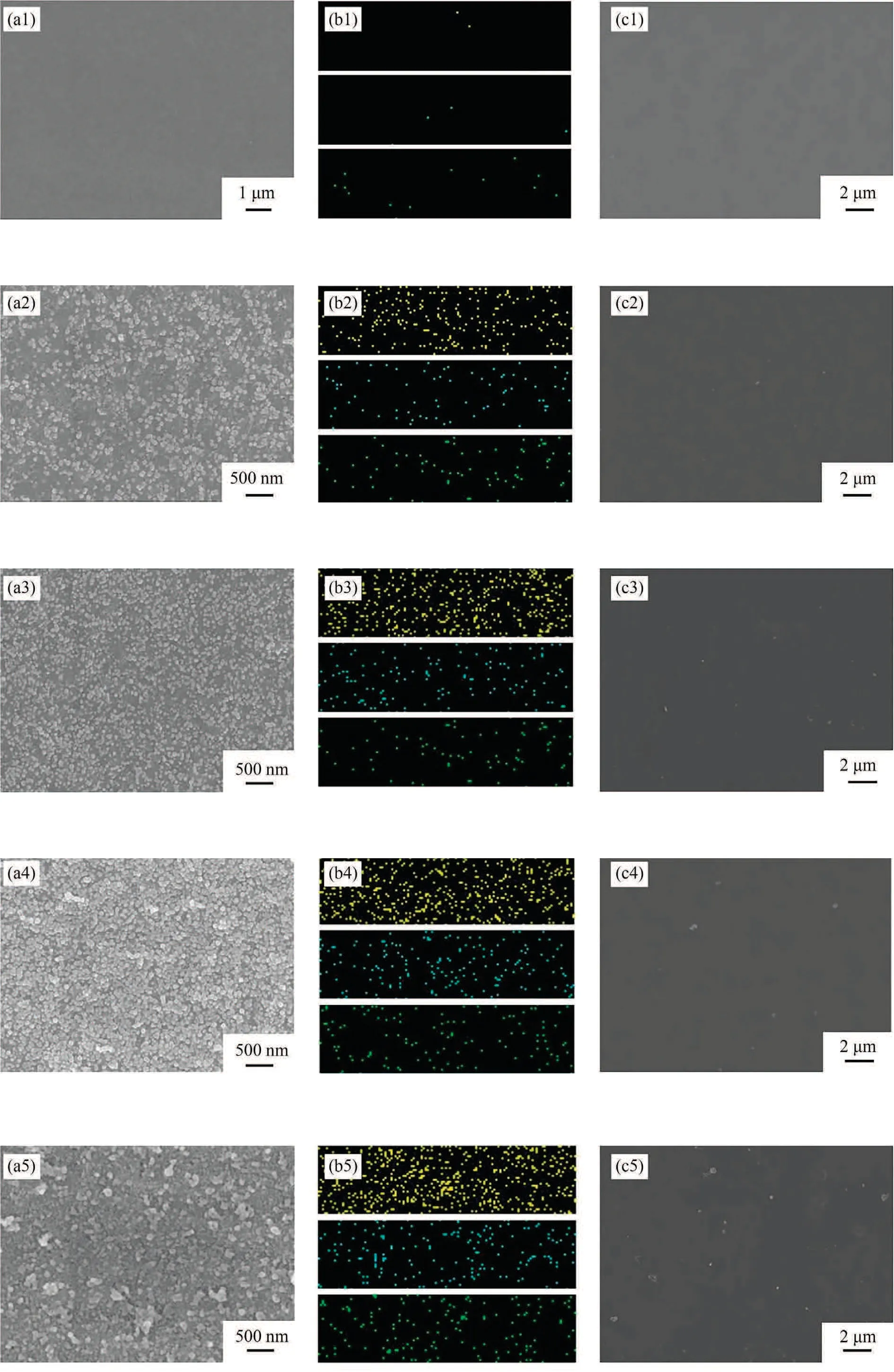
Fig.7.Surface SEM images (a1)-(a5) and mapping (b1)-(b5) of Zn (yellow), N (blue) and O (green) of the ZIF-8/PVDF membranes, and the surface SEM images of the ZIF-8@PEBAX/PVDF membranes (c1)-(c5).
Fig.8 shows the cross-sectional and mapping images of two different membranes: 1.5 h-ZIF-8/PVDF and 1.5 h-ZIF-8@PEBAX/PVDF.In Fig.8(a1), there is a thin ZIF-8 layer on top of the porous PVDF supporting membrane.In Fig.8(b1), a thin PEBAX layer(about 424.3 nm) is well connected to the ZIF-8/PVDF layer.The mapping images indicate that both Zn and N elements are present in the cross-section of both membranes, indicating that these elements have penetrated into the membrane during the process of membrane surface modification by soaking in Zn(NO3)2and dimethylimidazole solution for a long time.However, due to the small pores in the PVDF section, the molecules are unable to rearrange into large enough nuclei to form macroscopic ZIF-8 particles[34].Therefore, no ZIF-8 particles are observed on the crosssection.Additionally, when comparing Fig.8(b4) with Fig.8(a4),it becomes apparent that O element becomes signifiacantly denser on the separation layer due to the introduction of PEBAX layer.

Fig.8.The cross-section and mapping image of 1.5 h-ZIF-8/PVDF membranes (a1)-(a4), 1.5 h-ZIF-8@PEBAX/PVDF membranes (b1)-(b4).
3.1.5.Positron annihilation spectroscopy (PAS) of membranes
When it comes to the Doppler’s parameter, a higher value typically indicates a higher open-volume defect or a higher free volume of the polymer membrane, and vice versa [33].The mean probe depth R (nm) is calculated as follows [35].
where ρ is the polymer membrane’s density (g·cm-3), and E is the positron energy (keV).The positron annihilation property of the Doppler broadening spectrum is usually characterized by the S parameter, which is defined as the ratio of the integral count of the central region of the incident energy range to that of the total region of the energy range.From Fig.9,it can be observed that when the value of E increases from 0 keV to 3 keV,the S parameter of pure PEBAX is the largest.However, for the modified membranes, the S parameter first increases and then decreases with extending the in-situ growth time, reaching the maximum at the in-situ growth time of 1 h.At this point, the detection depth is within the PEBAX layer, indicating that the free volume of pure PEBAX membrane is the largest, followed by the 1.5 h-ZIF-8@PEBAX/PVDF membrane.As the incident electron energy increases to 3 keV, the detection depth also increases, and the amount of positrons returning to the surface decreases, resulting in a gradual decrease in the S parameter.When the incident electron energy reaches 12 keV, it becomes relatively stable, indicating that the implanted depth may have reached the PVDF layer at this point.In the PVDF layer,the S parameters of the ZIF-8/PVDF membranes are greater than those of the pure PEBAX membrane.This means that the free volume of ZIF-8@PEBAX/PVDF are larger than that of the pristine PEBAX membrane at this depth range, which can be attributed to the reduced penetration of PEBAX into PVDF layer due to the introduction of ZIF-8 particles.

Fig.9.The spectra of the S parameter of the prepared nanocomposite membranes.
3.2.Pervaporation performance
3.2.1.Influence of the in-situ grown time
The pervaporation desulfurization performance was tested for membranes grown in-situ for different periods (0 h, 0.5 h, 1 h,1.5 h, 2 h) under the condition of feed thiophene concentration of 200 mg·L-1at 65 °C.It can be found from Fig.10 (a) that the enrichment factor of thiophene reaches the highest at in-situ grown time of 1.5 h, while the permeation flux of pristine PEBAX/PVDF membrane is the largest, and then shows a tendency of increasing first and then decreasing.In addition,Fig.10(b) indicates that the permeability and selectivity followed the same trend as the flux and enrichment factor shown in Fig.10(a).

Fig.10.Influence of the in-situ grown time on separation property of the ZIF-8@PEBAX/PVDF membranes.
In this experiment, the PVDF surface was first modified, then ZIF-8 particles were grown by self-assembly and in-situ grown,and finally coated the PEBAX separation layer.Fig.9 shows that the pristine PEBAX/PVDF membrane has a larger free volume than the ZIF-8 particles modified ZIF-8@PEBAX/PVDF membrane.As a result, the fluxes of all the modified membranes are generally lower than that of the PEBAX/PVDF membrane.The free volume of ZIF-8@PEBAX/PVDF is related to the content of ZIF-8 particles in the composite membrane [36].It reaches its maximum at the in-situ growth time of 1 h and then decreases.The trend of permeation flux for membranes follows the results of the free volume characterization shown in Fig.9.When the in-situ grown time is less than 1.5 h,the enrichment factor enhances due to the property of ZIF-8 of preferential adsorption of thiophene [35].However, as the in-situ grown time increases beyond 1.5 h, the selectivity and enrichment factor of the membrane decreases due to the difference in diffusion rate between n-heptane and thiophene[37].When the in-situ grown time is 1.5 h, the separation performance of the membrane is optimal.At this time, the total flux and the enrichment factor are 27.80 kg·m-2·h-1and 6.9, respectively.As a result,the 1.5 h-ZIF-8@PEBAX/PVDF membrane was selected for evaluation in the subsequent experiments.
3.2.2.Influence of feed temperature
To investigate the effect of the operating temperature, the pervaporation experiment of the 1.5 h-ZIF-8@PEBAX/PVDF membrane with feed thiophene content of 200 ppm was conducted.As illustrated in Fig.11(a), the total flux is monotonically increasing with increasing temperature.However, the enrichment factor reaches the peak at 65°C.The trend of flux can be attributed to the increase of free volume due to the enhancement of molecular thermal motion of the PEBAX polymer chain and the vapor pressure of both thiophene and n-heptane.This notion is also confirmed by the variety of partial fluxes of thiophene and n-heptane, which is illustrated in Fig.11(b).This phenomenon can be used to described using the dissolution-diffusion mechanism.The dissolution process dominates this process at low temperatures.At first, the enrichment factor increases due to the high adsorption selectivity of ZIF-8 particles to thiophene.With further increasing temperature, the process is changed to diffusion control.The diffusion velocity of n-heptane is faster than that of thiophene[37],resulting in more n-heptane passing through the membrane,which reduces the enrichment factor.
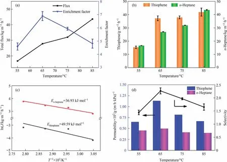
Fig.11.Influence of temperature on (a) flux and enrichment factor; (b) the partial flux of thiophene and n-heptane; (c) Arrhenius plots; (d) permeability and selectivity of the 1.5 h-ZIF-8@PEBAX/PVDF membrane.
The influence of temperature can be quantitatively described using the Arrhenius formula, as shown below.
where Ji(kg·m-2·h-1) represents the respective fluxes of the feed components, Joi(kg·m-2·h-1) refers the permeation flux constant,and Ep(kJ·mol-1) refer to the apparent activation energy of each component, R (J·mol-1·K-1) represents the molar gas constant,and T (K) is the temperature at this operating condition.Fig.11(c)shows the Arrhenius curve with the 1.5 h-ZIF-8@PEBAX/PVDF membranes.The apparent activation energy of thiophene is bigger than that of n-heptane, which indicates that the temperature changes have a more pronounced effect on thiophene.The changes of membrane permeability and selectivity are shown in Fig.11(d),which shows that with the increase of temperature,the permeability of thiophene and n-heptane both have a maximum.The permeability of thiophene is always greater than that of n-heptane, and the permeability of thiophene is more affected by temperature than that of n-heptane.Meanwhile,the change trend of selectivity with temperature is the same as that of enrichment factor, both reaching the maximum value at 65 °C.
3.2.3.Influence of feed concentration
Fig.12 exhibits the effect of the feed concentration on the separation property of the 1.5 h-ZIF-8@PEBAX/PVDF membrane.The flux of the membrane is a monotone increasing function of feed thiophene concentration, whereas the enrichment factor is quite reverse.The swelling degree of the membrane increases with increasing the thiophene content of feed solution, resulting in the permeating of massive n-heptane, so the flux enhances.Furthermore, the adsorption site for thiophene of the membrane is limited.So increasing the feed concentration, the permeability of thiophene gradually decreases, while the permeability of nheptane increases accordingly,which reduce the enrichment factor and selectivity.
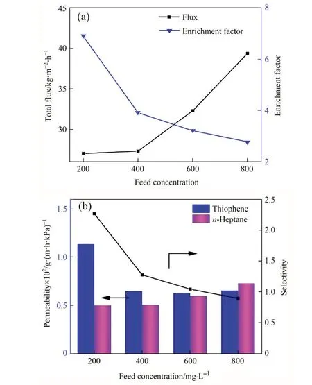
Fig.12.Effect of feed concentration on (a) flux and enrichment factor; (b) permeability and selectivity of the 1.5 h-ZIF-8@PEBAX/PVDF membrane.
3.2.4.Long-time operation stability
Fig.13 shows the long time stability of the 1.5 h-ZIF-8@PEBAX/PVDF composite membrane.The operating temperature and feed thiophene concentration are 65 °C and 200 mg·L-1, respectively.During continuous operation for 10 d,both the flux and the enrichment factor floating range are very little, and the stable flux and enrichment factor are about 28 kg·m-2·h-1and 5.8, respectively.This indicates that the separation property of the prepared ZIF-8@PEBAX/PVDF is relatively steady.

Fig.13.Long-term stability of the 1.5 h-ZIF-8@PEBAX/PVDF membrane.
3.2.5.Comparison of performance of membranes
The performance comparison of the membranes in our work with the relevant literature [16,24,38-46] is exhibited in Fig.14.The permeation flux of our prepared ZIF-8 particles modified PEBAX membrane is better than that of other reported membrane.The result suggest that the performance of the membrane can be increased with the incorporation of ZIF-8 particles via selfassembly and in-situ grown method, which maybe provide a promising approach for developing desulfurization membranes with excellent separation performance in the future.

Fig.14.Comparison of performance of our prepared membranes and other membrane.
4.Conclusions
More and more ZIF-8 particles are formed on the PVDF supporting membrane with increasing the in-situ grown time.The free volume of ZIF-8@PEBAX/PVDF membrane is affected by the content of ZIF-8 particles, which further influences the membrane separation performance.With increasing temperature, the total flux is increasing whereas the enrichment factor reaches its maximum at 65 °C.With increasing the feed thiophene concentration, the flux of the membrane is a monotone increasing whereas the enrich-ment factor is quite reverse.When the in-situ growth time is 1.5 h, the optimal flux (27.80 kg·m-2·h-1) and enrichment factor (6.9) of ZIF-8@PEBAX/PVDF membrane is obtained.The membrane also exhibits long-term operational stability, indicating that the combination of self-assembly and in-situ growth can be used to effectively enhance the desulfurization performance of the membranes.
DataAvailability
Data will be made available on request.
Declaration of Competing Interest
The authors declare that they have no known competing financial interests or personal relationships that could have appeared to influence the work reported in this paper.
Acknowledgements
This work was financially supported by the National Natural Science Foundation of China (22271022) and Hubei Three Gorges Laboratory (SK212001).
 Chinese Journal of Chemical Engineering2023年12期
- Chinese Journal of Chemical Engineering的其它文章
- Intrinsic kinetics of catalytic hydrogenation of 2-nitro-4-acetylamino anisole to 2-amino-4-acetylamino anisole over Raney nickel catalyst
- Experiments and model development of p-nitrochlorobenzene and naphthalene purification in a continuous tower melting crystallizer
- α-Synuclein: A fusion chaperone significantly boosting the enzymatic performance of PET hydrolase
- Influence of water vapor on the separation of volatile organic compound/nitrogen mixture by polydimethylsiloxane membrane
- Mass transfer mechanism and relationship of gas-liquid annular flow in a microfluidic cross-junction device
- Enhanced photocatalytic activity of methylene blue using heterojunction Ag@TiO2 nanocomposite: Mechanistic and optimization study
