Tailoring the separation performance of a carbon nanotube-based mixed matrix membrane decorated with metal-organic framework
Hui-Yong Wu, Hong-Xin Fu, Yu Liu, Xiao-Sa Zhang, Wen-Ze Li,, Jian Luan2,
1 College of Science, Shenyang University of Chemical Technology, Shenyang 110142, China
2 College of Sciences, Northeastern University, Shenyang 110819, China
Keywords:Composites Carbon nanotube Metal-organic framework Organic crosslinking Selectivity Adsorbents
ABSTRACT Synthesis of mixed matrix membranes(MMM)using carbon nanotubes(CNTs)has shown great prospects for achieving excellent selective separation because of its special structure.Nevertheless,the preparation of highly selective MMM faces challenges,which is attributed to the obstacles encountered by CNTs dispersion in polymer matrix and elimination of interface defects.A novel CNT-based composite decorated with metal-organic framework(MOF)was synthesized and applied to the preparation of MMM.MOF was post modified,and then carboxyl groups were inserted on the outer surface of CNTs.The synthetic MMM(Cu-MOF-en@MWCNT) not only has selective adsorption on dyes, but also has selective photodegradation on dyes.The method of using CNTs to wrap the outside of MOF has great potential in dye separation.The performance of MMM was further improved by decorating MOF on the filler to improve the selectivity to the designated dye.
1.Introduction
Membrane technology has become an efficient separation technology for the separation of ions,gas molecules and organic molecules [1-4].Due to the limit of Robson upper limit, the permeability and selectivity of most membrane materials are inversely proportional [5].More and more researchers have introduced inorganic particles into polymer matrix and made great breakthroughs [6].The prepared mixed matrix membranes(MMM) combines the advantages of filler particles and polymer membranes, wherein the filler particles provide high separation performance and the polymer provides good processing and mechanical properties [7].
Carbon nanotubes (CNTs) stands out among various fillers because of its special structure [8].Especially outstanding is the high aspect ratio and large specific surface area of CNT, which makes it have excellent performance in the field of molecular or ion adsorption and separation [9].Unfortunately, hydrophobic CNTs have a large van der Waals force, which makes it difficult for them to separate and agglomerate together.The aggregation of CNTs hinders the preparation of highly selective MMM for separated gases.Various surface modification strategies explored so far have solved the interface defects and improved the dispersion ability of CNTs in the polymer matrix [10,11].Carboxylation can be achieved by grafting functional groups onto the outer surface of CNTs with strong acids [12].It can also be doped or functionalized on the outer surface of CNTs.This has the advantage of improving the dispersion ability and increasing the solubility of penetrant in the composite membrane[13].However,some methods also have the disadvantage of destroying the integrity of CNTs,making it an unsuitable filler.In addition,the polymer substrate in MMM materials also greatly limits the porosity of the material.
As one of the new porous hybrid materials, MOFs have significant advantages in specific surface area, pore structure and selective adsorption [14-17].In addition, organic linkers such as-NH2and -COO can easily complete the work of MOF during the synthesis process.The atom ratio of metal organic linker is changed to synthesize various structures to improve the selective adsorption capacity of designated molecules or ions[18].It is a feasible strategy to modify MOF on carbon nanotubes by using the self supporting film forming technology of carbon nanotubes and improving the porosity of materials to improve the selective adsorption performance of carbon nanotubes.
In this work,we report a novel filler of MMMs derived from the growth of an aminated MOF on the outer surface of carboxylated CNTs to enhance selective adsorption and photocatalytic performance.CNTs coated with MOF was successfully prepared (Cu-MOF-en@MWCNT).Cu-MOF-en introduced amino groups and active sites to the external surface of CNTs.The synthesized Cu-MOF-en@MWCNT MMM was fabricated by suction filtration loading on nylon filter paper (Fig.1).
2.Experimental
2.1.Materials and methods
The preparation methods of 3-bpah have been reported in the past [19].Other reagents, solvents and gases used in the experiment come from commercial sources (reagent grade) and are directly used without purification.
2.2.Synthesis of crystalline Cu-MOF
A mixture containing copper salt (such as CuCl2·2H2O, Cu(NO3)2·3H2O,Cu(CH3COO)2·H2O),0.20 mmol),3-bpah(0.10 mmol)1,4-H2NDC (0.15 mmol), NaOH (0.40 mmol) and H2O (12 ml) was stored in a 20 ml polytetrafluoroethylene lined autoclave at 120 °C.After 96 h, wait for the temperature to cool to the same as the ambient temperature and Cu-MOF ([Cu2(3-bpah)(1,4-NDC)2]·(1,4-H2NDC)·3H2O) crystals were successfully prepared(Fig.2).Yield 30%-40% based on Cu.Anal.Calcd.for C54H46Cu2N4-O17: C 56.35, H 4.00, N 4.87.Found: C 56.38, H 3.96, N 4.89%.υmax(KBr)/cm-1:3279(s),2933(m),2335(w),1702(s),1628(m),1609(s),1554(s),1515(m),1453(m),1421(s),1367(s),1283(w),1246(w), 1114 (w), 1048 (w), 868 (w), 830 (s), 782 (m), 738 (w), 699(w), 600 (w).
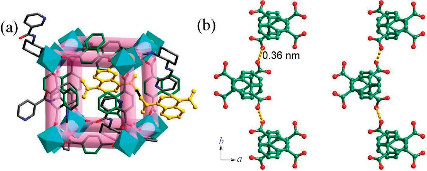
Fig.2.(a) The crystal structure of Cu-MOF; (b) the hydrogen bonding interactions among the 1,4-H2NDC in Cu-MOF.
2.3.Synthesis of nano Cu-MOF
The synthesis of nano Cu-MOF is similar to crystalline Cu-MOF.The difference is that the synthetic method is reflux instead of hydrothermal synthesis.Continue heating at 120 °C for 12 h, and rapidly cool the mixture to ambient temperature to accelerate crystallization.Centrifuge and wash the product, then the product(nano Cu-MOF) is active at 120 °C for 1 h before modification.
2.4.Synthesis of CNTs
At ambient temperature, mix Fe(NO3)3·9H2O (0.2 mol), Al(NO3)3·9H2O (0.1 mol) and NaOH (0.1 mol) in 80 ml of water and stir evenly for 1 hour.The solid dried at 100 °C was heated in air at 500 °C for 2.5 h to collect oxidized catalyst precursor.Then it was slowly cooled to ambient temperature, and the catalyst (Fe catalyst) was collected through ball milling and filtration.Put 80 mg of Fe-catalyst placed in the quartz boat into the quartz tube,heat it to 800 °C, and first introduce pure N2(240 ml·min-1(standard condition)) for washing for 30 minutes; then introduce H2(200 ml·min-1) for 80 minutes to deoxidize the catalyst.After deoxidation, disconnect the gas flow, burn the furnace to 800 °C, and then use the mixed gas flow composed of C3H6(100 ml·min-1), N2(240 ml·min-1), and H2(20 ml·min-1) to flow for 1 h instead of N2, then change into N2flow, and reduce the temperature in the furnace to room temperature [20].
2.5.Synthesis of CNT-COOH
Prepare concentrated nitric acid and concentrated sulfuric acid with a volume ratio of 3:1, and immerse CNT in them at 80 °C for 24 h, stir constantly during this period, filter and recover, wash with deionized water, and dry at 80 °C to obtain the product CNT-COOH.
2.6.Post-modification of nano Cu-MOF with ethylenediamine (Cu-MOF-en)
100 mg Cu-MOF microspheres were dispersed in 10 ml DMSO,then 0.1 ml triphenyl phosphite and 0.2 ml ethylenediamine were dropped into the suspension, and ultrasonic treatment was performed at room temperature for 1 h.The product is separated by centrifugation and washed three times with n-hexane.The obtained powder was dried at 80 °C.
2.7.Synthesis of MOF-CNT membrane
First, a certain amount of Cu-MOF-en powder (30 mg) and 30 mg CNT-COOH were dispersed into 10 ml toluene and 0.4 ml triethylamine, respectively.Second, the mixture was carried out at 25°C for 30 min under ultrasonic treatment.Third,the solution is heated at 100 °C for 1 h, then cooled down to ambient temperature, after washing with ethanol for three times, supported by nylon filter paper and suction filtered into membrane (Fig.3).
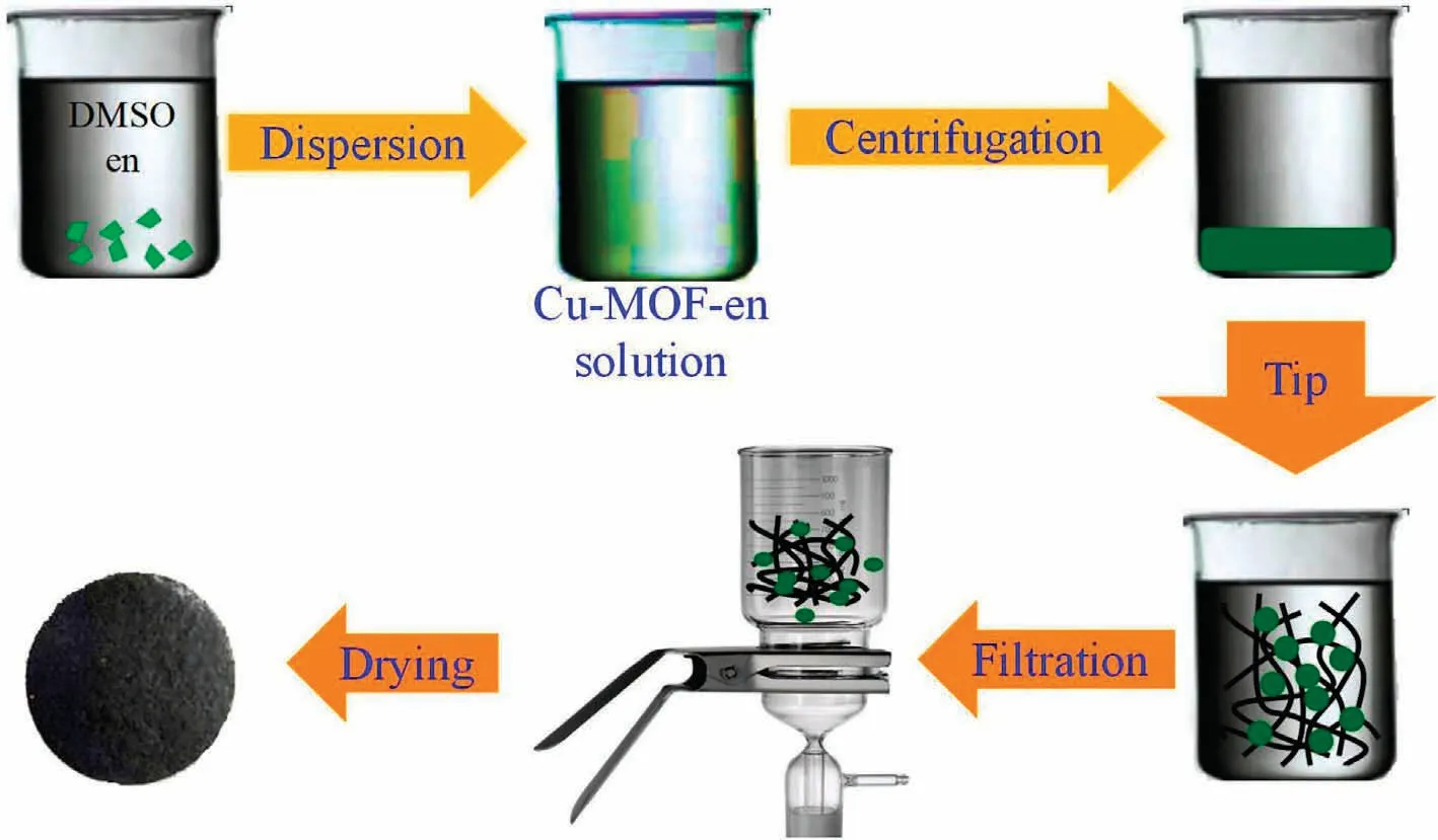
Fig.3.The self-assembly process of MOF-CNT membrane.
2.8.Dye separation experiments
The adsorption and photodegradation properties of five dyes(methylene blue (MB), Rhodamine B (RhB), crystal violet (GV),methyl orange (MO) and Congo red (CR) were evaluated through adsorption and photocatalytic experiments.Put 5 mg of material into 50 ml of different dyes (the concentration of MB, RhB, GV,MO and CR are 10 mg·L-1, 10 mg·L-1, 10 mg·L-1, 40 mg·L-1and 80 mg·L-1), respectively.The light source in the photodegradation experiment comes from a 20 W high-pressure mercury lamp, and an external strong magnet was introduced to separate the adsorbent/photocatalyst.During the adsorption and photodegradation experiments, the change in absorbance in each mixture was observed and recorded every 30 min using an ultraviolet spectrophotometer.
2.9.Characterization
Perkin-Elmer 240C elemental analyzer were used for the analysis of elements (C, H, and N).Infrared spectroscopy (KBr doped)was measured using the Varian 640-IR spectrometer.Measurement of X-ray diffraction with Rigaku diffractometer (using Cu Kα Radiated powder).The sample image was taken by scanning electron microscope (SEM, Nova Nano SEM 430) and highresolution transmission electron microscope (HRTEM,JEOL2010200kV).The thermal stabilities of the sample were tested by thermogravimetric analyzer (NETZSCH STA 449C).The surface defects of the samples were evaluated by laser Raman spectroscopy.Automatic volume adsorption analyzer (ASAP 2020M) is used to test pore structure and specific surface area.X-ray photoelectron spectroscopy (XPS) measurements were performed on an ESCALAB 250 X-ray photoelectron spectrometer equipped with an Al Kα anode(1486.6 eV photon energy,300 W).The dye adsorption and photodegradation were tested with SP-1900 UV-Vis spectrophotometer.
3.Results and Discussion
3.1.Effect of the counter anions on the structures of Cu-MOFs
Table 1 shows the difference of synthetic products using different copper salts.The result indicated that the sizes of Cu-MOFs are Cl->NO3->CH3COO-.Therefore, different anions have obvious effects on the structure.The analysis shows that the Cu-MOF prepared by adding CH3COO-has the advantages of smaller size and larger productivity, using its advantages can be used to prepare nano crystal.
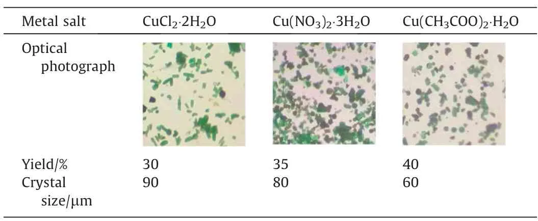
Table 1 Comparison of Cu-MOF synthesized by different copper salts(optical photo yield and crystal size)
3.2.Effect of the preparation method on the structures of Cu-MOFs
In order to obtain smaller size of Cu-MOF, the nano-Cu-MOF was prepared by reflux method.As shown in Fig.4(a) and (b),the SEM and optical microscope of Cu-MOF synthesized by hydrothermal method are shown dispersed crystal with the size of 60 μm.On the contrary, the nano Cu-MOF is relatively aggregated with a cone shape and a size of about 4 μm.The IR vibration curve is shown in Fig.4(c).The vibration region of Cu-MOF at 1380 cm-1and 1040 cm-1and the vibration region of nano Cu-MOF at 1383 cm-1and 1046 cm-1were caused by the vC-Nand vN-Hvibrations in the pyridine ring of 3-bpah ligand, respectively[20].The vibration at 1425 cm-1and 1413 cm-1corresponds to the carboxyl group.The characteristic bands at 1623 cm-1for Cu-MOF and 1616 cm-1for nano Cu-MOF are assigned to the vC=Ovibration of amide group, respectively [21].The -OH group in the water molecule overlaps with the vN-Hvibration and corresponds to them at 3405 cm-1and 3437 cm-1, respectively[21].The -COOH group vibration at 1714 cm-1[21].The PXRD curves of them are very similar to the simulated Cu-MOF curves, which confirm the successful synthesis of Cu-MOF and nano Cu-MOF (Fig.4(d)).TheCu-MOF created by the reflux approach has broader and weaker peaks, resulting in lesser crystallinity compared to the Cu-MOF prepared by the hydrothermal method, leading to smaller particle size, which is compatible with the findings of SEM.The TGA pictures of them are shown in Fig.4(e), which shown two major weight decreases were observed.The first is due to dehydration,and the temperatures are about 60 °C.The second weight losses are around 230°C,and the carbon skeleton collapses.Importantly,the dehydration and decomposition timing of the two are almost the same,which may be due to their similar chemical composition and structure.In conclusion, both methods can prepare Cu-MOF,but it is better to use the reflux method.

Fig.4.(a) SEM images and optical microscope photos of Cu-MOF; (b) SEM images and optical microscope photos of nano Cu-MOF; (c) IR analysis of Cu-MOF and nano Cu-MOF; (d) PXRD analysis of Cu-MOF and nano Cu-MOF; (e) TGA analysis of Cu-MOF and nano Cu-MOF.
3.3.Acid treatment MWCNTs analysis
SEM results showed that MWCNTs were well dispersed after acid treatment (Fig.5(a)-(d)).The diameter became smaller and the tubular structure did not change significantly except for the catalyst removed [20].Fig.S1 (Supplementary Material) shows the IR spectra of MWCNTs before and after acidification.Compared with origin MWCNT spectrum, the significant band change of MWCNT-COOH spectrum is caused by the entry of carboxylic acid groups,at 3470 cm-1and 3550 cm-1[22].Obviously,the carboxyl group was successfully introduced by the action of acid oxidation.The quality and defects of origin MWCNT and MWCNT-COOH were compared by Raman spectroscopy.The ID/IGvalue is commonly used as the standard to evaluate the surface defect content of MWCNTs.It can be seen from Fig.5(e), after carboxylation of the MWCNTs, the IG/IDintensity ratio decreases.This represents the increase of MWCNT-COOH crystal defects, and also confirms the successful introduction of -COOH to the surface of MWCNT.The thermal stability curve of the material is shown in Fig.5(f).The carbon structure of origin MWCNT decomposes at about 650 °C, and the carbon framework of MWCNT-COOH collapses at about 400 °C.This indicates that the thermal stability of carbon tubes after carboxylation treatment is lower.The porous natures and specific surface areas of the origin MWCNT and MWCNT-COOH were investigated by nitrogen adsorption(Fig.S2).The BET surface area of origin MWCNT and MWCNT-COOH are 163.62 and 165.28 m2·g-1.According to the IUPAC classification,they are consistent with type III isotherms.
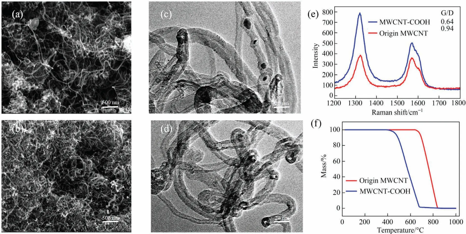
Fig.5.(a) SEM and (b) TEM photos of origin MWCNT.(c) SEM and (d) TEM photos of MWCNT-COOH.(e) Raman patterns.(f) TGA curves.
3.4.Grafting strategy
The modified material is called Cu-MOF-en.SEM characterization results are shown in Fig.6(a)and(b),Cu-MOF-en is in a polyhedral block shape.The modification results of Cu-MOF by amines are evidenced by the FT-IR spectra (Fig.6(c)).For Cu-MOF-en, the symmetric and asymmetric vibrations of -NH2are shown at 3335 and 3271 cm-1.C-H(aliphatic)and C-N(aliphatic)stretching vibration bands appeared at 2959 and 1035 cm-1,respectively,because of the introduction of alkyl amines.To sum up, amine functionalized Cu-MOF was successfully synthesized [23,24].Fig.6(d)shows the PXRD image of Cu-MOF-en.The results showed that the diffraction peak of Cu-MOF-en changed when ethylenediamine was grafted onto Cu-MOF.Compared with Cu-MOF,the peak of Cu-MOF-en disappeared near 8.3°and a new diffraction peak appeared near 16.5°[25].It is proved that the carboxyl group of bare leakage in Cu-MOF disappears and Cu-MOF-en forms amide,which corresponds to the FT-IR results indicating that Cu-MoF-en was successfully prepared [26].
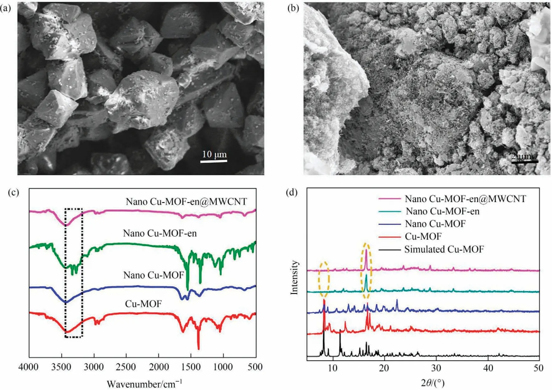
Fig.6.(a) SEM image of Cu-MOF-en; (b) SEM image of Cu-MOF-en@MWCNT; (c) FT-IR spectra; (d) PXRD patterns.
3.5.Cu-MOF-en@MWCNT membrane analyses
Cu-MOF-en@MWCNT was characterized by SEM.The corresponding SEM images are shown in Fig.6(b).MWCNT is tightly wound around Cu-MOF, and Cu-MOF is wrapped by dense pipes.The FT-IR results indicate that the distinct band at 3335 and 3271 cm-1disappears which verifies that the Cu-MOFen@MWCNT has been successfully prepared (Fig.6(c)) [24].The PXRD patterns in Fig.6(d) shows that Cu-MOF-en@MWCNT successfully synthesized.In order to further verify the structure of the MMM, XPS was measured.As shown in Fig.7(a), C, N, O, and Cu exist in the as-prepared MMM.The result of N 1s XPS spectra indicated that the pyridine nitrogen in the MMM was at 399.5 eV, and the nitrogen of amide was at 400.9 eV (Fig.7(b))[27].It can be seen that there were three XPS peaks of O 1s,which appeared at 530.6 eV, 531.5 eV and 532.9 eV, respectively, which assigned to O-H groups, free carboxyl groups and C=O groups(Fig.7(c)) [27-29].Fig.7(d) could be deconvoluted into three peaks: C-N bond at 283.9 eV, C=C bond at 284.8 eV, and C-C bond at 285.5 eV, respectively [30,31].Fig.7(e) shows the spectra of Cu 2p.The peaks at 934.2 eV, 942.6 eV and 953.9 eV belonged to Cu 2p3/2, Cu 2p, and Cu 2p1/2[32].These peaks indicated that MWCNT had been successfully added to the composite material.BET analysis revealed the nitrogen adsorption and desorption isotherm(Fig.7(f)), the pore size distribution (insert of Fig.7(f)) and specific surface area (36.855 m2·g-1) of the MMM.Under neutral conditions, the zeta potential value of the MMM is 0.269 mV, and the material has a positive surface.Use a high-speed camera system to record the wetting behavior of water droplets on the MMM surface (Fig.S3).When water droplets come into contact with the surface of the membrane, they quickly diffuse, indicating the superhydrophilicity of the MMM.

Fig.7.(a-e) XPS analysis of the MMM.(f) Nitrogen adsorption and desorption isotherms of the MMM (insert: the pore size distribution of the MMM).
3.6.Selective dye adsorption
In this part, the following five dyes MB, RhB, GV, MO and CR(Table S1) are selected to investigate adsorption behavior of Cu-MOF-en@MWCNT (Fig.8(a)-(e)).Cu-MOF-en@MWCNT in 4 h at room temperature, the adsorption capacities of MB, RhB, GV, MO and CR were 15.10, 17.55, 14.27, 53.90 and 1216.92 mg·g-1,respectively(Fig.8(f)),which shows excellent selective adsorption performance.In order to further confirmation Cu-MOFen@MWCNT selective adsorption performance: mix CR and GV with equal volume to prepare mixed solution(Fig.8(g)).As a result,the CR peak decreased significantly, while the GV peak decreased slightly.Moreover, it shows that the color of mixed dyes changes from positive red to lavender, which demonstrates that Cu-MOFen@MWCNT is an ideal adsorbent for removing CR from mixed dyes.Furthermore, Cu-MOF-en@MWCNT selective adsorption CR can be attributed to the following three reasons.First, A hydrogen bond is formed between the-C=O group of Cu-MOF-en@MWCNT and the-NH2group of CR,this may be the main reason why CR has the best adsorption capacity [33].Secondly, Cu-MOF-en@MWCNT possesses porous, which leads to more adsorption space and adsorption sites.Finally,π-π stacking exists between the benzene ring of Cu-MOF and the aromatic ring of CR.
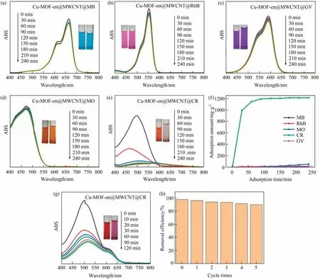
Fig.8.(a-e) Adsorption curves of five dye solutions; (f) the adsorption capacities of five dye solution with Cu-MOF-en@MWCNT; (g) UV-vis spectra of CR and GV mixed solution; (h) reusability of Cu-MOF-en@MWCNT for CR adsorption.
The regeneration and recycling ability of adsorbent is very critical in large-scale practical applications.The recoverability test of Cu-MOF-en@MWCNT was conducted under 50 ml of CR solution and 5 mg of adsorbent.After every 240 min of adsorption test,clean Cu-MOF-en@MWCNT with ethanol.Dry the sample at 50 °C and continue the cyclic adsorption experiment.After five cycles of experiments, its adsorption capacity has not decreased significantly (Fig.8(h)), indicate Cu-MOF-en@MWCNT has reversible adsorption and desorption capacity.
3.7.Selective dye photodegradation
Cu-MOFs can not only absorb dyes, but also photolysis dyes[34].We have evaluated the photocatalytic performance of Cu-MOF-en@MWCNT on five dyes (Fig.9(a)-(e)).Fig.9(f) shows that the photodegradation efficiency of MB, RhB, GV, MO and CR are 20.75%, 8.93%, 92.07%, 4.42% and 79.11% respectively.The experiment shows that Cu-MOF-en@MWCNT can efficiently select GV and CR.To better verify this view,mix GV and MO with equal volume to prepare mixed solution,(Fig.9(g)).As a result,the GV peak decreased significantly, while the MO peak decreased slightly.Moreover,it shows that the color of mixed dyes changes from dark red to yellow,which demonstrates that Cu-MOF-en@MWCNT is an ideal photocatalyst for removing GV from mixed dyes.In order to evaluate this photocatalyst, the catalytic recovery performance was studied.Fig.9(h) showed that the degradation efficiency of Cu-MOF for GV was 90.28% at the end of the fifth cycle under UV light irradiation,indicating that the photocatalyst had good recoverability.Furthermore,we found that the degradation performance of cationic dyes is better than that of anionic dyes(GV >MB >RhB >MO), which may be attributed to the molecular size (Table S2).
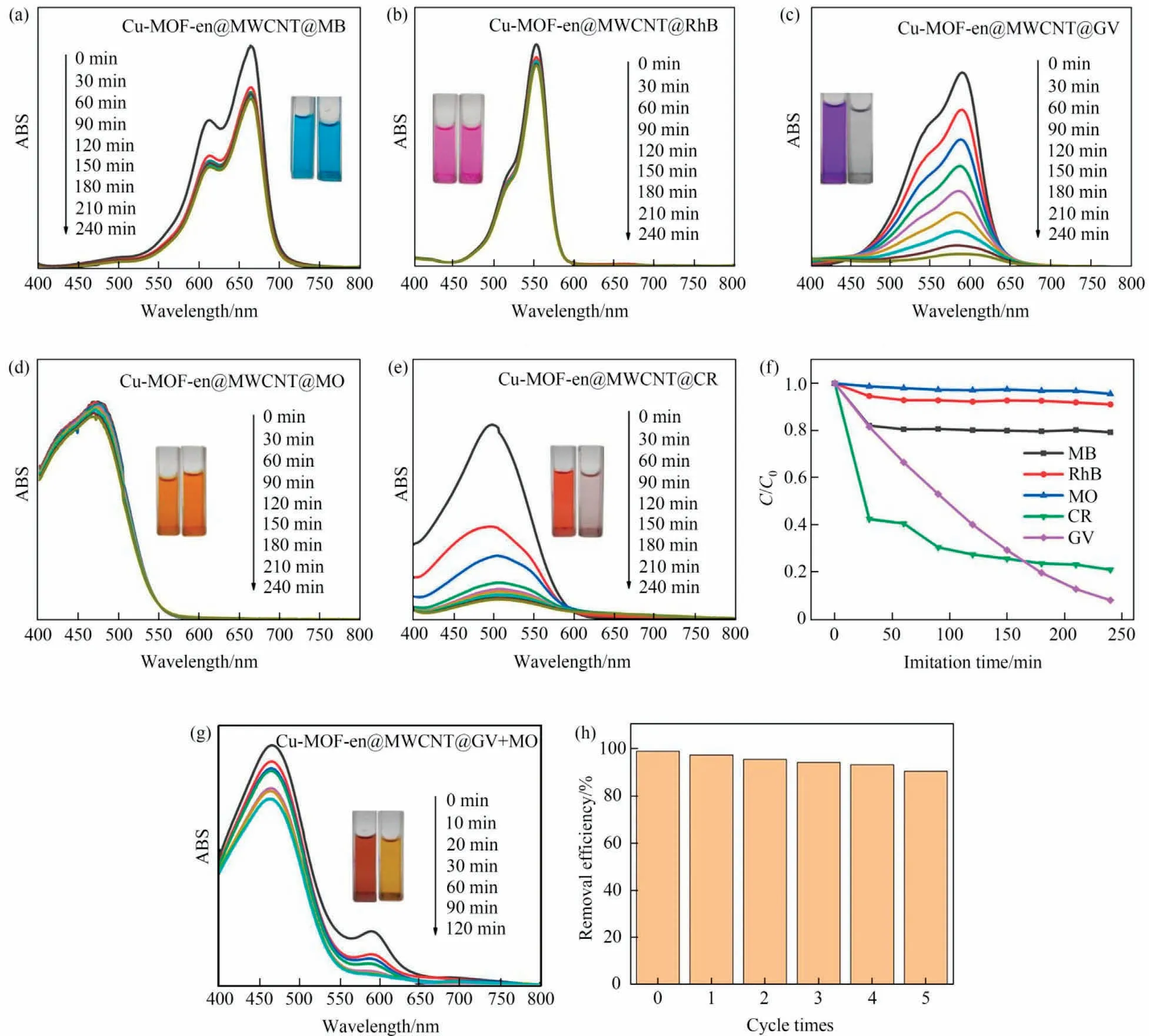
Fig.9.(a-e) Photodegradation curves of five dye solutions; (f) the adsorption efficiency of five dye solution with Cu-MOF-en@MWCNT; (g) ultraviolet visible spectra of GV and MO mixed solution; (h)reusability of Cu-MOF-en@MWCNT for GV photodegradation.
As we know,photogenerated holes(h+),hydroxyl radicals(·OH)or oxygen radicals () radicals are closely related to the degradation of dyes, and ammonium oxalate (AO), tert-butanol (TBA) and benzoquinone (BQ) are their scavengers respectively [30,35].The capture experiment confirmed the degradation mechanism of GV,as shown in Fig.10.These three scavengers were not used, the degradation rate of Cu-MOF-en@MWCNT to GV was 92.07%.After using three scavengers (AO, TBA, BQ), the degradation rates were decreased to 67.11%, 57.33% and 71.74%, respectively.The results show that the oxygen activities of Cu-MOF-en@MWCNT in GV solution are mainly h+,·OH andunder UV light irradiation.
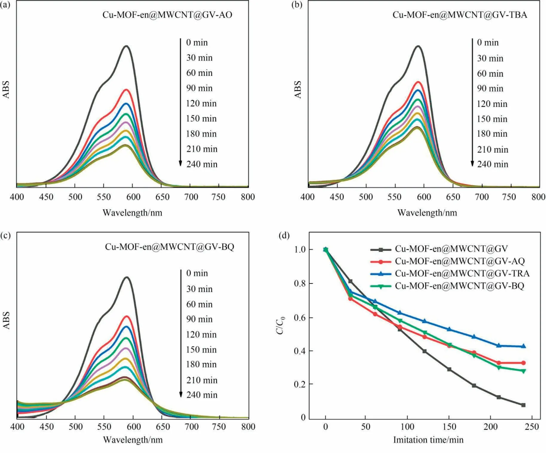
Fig.10.(a-c) Light degradation of GV solution.(d) Photodegradation efficiency.
When the photon energy is greater than the Cu-MOFen@MWCNT band gap width, it is accompanied by an electronic transition, which will go from the valence band to the conduction band,thus generating electrons and holes[36].On the one hand,h+are captured by hydroxyl and water molecules on the catalyst surface, which can not only improve oxidation, but also promote the reactivity of·OH [36].On the other hand, surface O2reacts with photogenerated electrons to form ·.It is worth noting that ·and·OH are the main active substances involved in the whole process,which can be used as strong oxidants to help the decomposition of organic dyes.Therefore,these phenomena prove that using Cu-MOF-en@MWCNT to remove dyes from water is an effective method.
4.Conclusions
In summary, we have reported a high-performance MMM utilizing a novel MOF-CNT composite filler for adsorption and photodegradation of dyes.The introduction of amino groups and active sites enables CNTs to encapsulate Cu-MOF-en.By modifying the strategy of MOF on the filler,we can design and develop better ways to improve the performance of Cu-MOF-en@MWCNT MMM.This composite also has a promising application in sensing and catalysis and so on.
Declaration of Competing Interest
The authors declare that they have no known competing financial interests or personal relationships that could have appeared to influence the work reported in this paper.
Acknowledgements
This work was financially supported by the Liaoning Provincial Department of Education Fund (LJKMZ20220793 and LJKMZ20220795), the Applied Basic Research Program of Liaoning Science and Technology Department (2023JH2/101300231).
Supplementary Material
Supplementary material to this article can be found online at https://doi.org/10.1016/j.cjche.2023.06.016.
 Chinese Journal of Chemical Engineering2023年12期
- Chinese Journal of Chemical Engineering的其它文章
- Intrinsic kinetics of catalytic hydrogenation of 2-nitro-4-acetylamino anisole to 2-amino-4-acetylamino anisole over Raney nickel catalyst
- Experiments and model development of p-nitrochlorobenzene and naphthalene purification in a continuous tower melting crystallizer
- α-Synuclein: A fusion chaperone significantly boosting the enzymatic performance of PET hydrolase
- Influence of water vapor on the separation of volatile organic compound/nitrogen mixture by polydimethylsiloxane membrane
- Mass transfer mechanism and relationship of gas-liquid annular flow in a microfluidic cross-junction device
- Enhanced photocatalytic activity of methylene blue using heterojunction Ag@TiO2 nanocomposite: Mechanistic and optimization study
