
Discussion on pile axial load test methods and their applicability in cold regions
2023-01-02 08:08JiaWeiGaoJiChenXinHouQiHangMeiYongHengLiu
JiaWei Gao,Ji Chen,Xin Hou,QiHang Mei,YongHeng Liu
1.Beiluhe Observation and Research Station on Frozen Soil Engineering and Environment in Qinghai-Tibet Plateau,State Key Laboratory of Frozen Soil Engineering,NIEER,CAS,Lanzhou,Gansu 730000,China
2.University of Chinese Academy of Sciences,Beijing 100049,China
ABSTRACT The measurement of pile axial load is of great significance to determining pile foundation design parameters such as skin friction and end bearing capacity and analyzing load transfer mechanisms.Affected by the temperature and ice content of frozen ground,the interface contact relationship between pile foundation and frozen soil is complicated,making pile axial load measurements more uncertain than that in non-frozen ground.Therefore,it is necessary to gain an in-depth understanding of the current pile axial load test methods.Four methods are systematically reviewed:vibrating wire sensors,strain gauges,sliding micrometers,and optical fiber strain sensors.At the same time,the applicability of the four test methods in frozen soil regions is discussed in detail.The first two methods are mature and commonly used.The sliding micrometer is only suitable for short-term measurement.While the Fiber Bragg grating(FBG)strain gauge meets the monitoring requirements,the Brillouin optical time-domain reflectometer(BOTDR)needs further verification.This paper aims to provide a technical reference for selecting and applying different methods in the pile axial load test for the stability study and bearing capacity assessment of pile foundations in cold regions.
Keywords:pile axial load;test methods;pile shaft resistance;sensors;cold regions
1 Introduction
Pile foundation has the advantages of high bearing capacity,small foundation settlement and differential deformation,excellent seismic performance,and broad applicability.It has become a foundation widely used in high-rise buildings,bridges,offshore platforms,water conservancy facilities,and nuclear power plants(Gao,2002;Shi,2015).As a structure that directly bears the upper load,pile foundation is subjected to concentrated load,which has strict requirements on the strength of the pile and effective load transfer between pile and soil.Accurately obtaining the distribution of the axial load is the key to determining the pile foundation design parameters such as pile shaft resistance and end bearing capacity.
The axial load test refers to the method of calculating the pile shaft and tip resistance by measuring the pile strain and displacement(MOHURD,2014).The pile axial load(Zhanget al.,2017)is first calculated by the data measured by the sensor.Then the pile shaft resistance(Liu,2016)and tip resistance(Zhang and Wu,2008)are converted based on the pile axial load.The different conditions of the construction site will affect the test results of the sensor,so the calculated and actual loads of the pile will also be different.The vibrating wire sensor,strain gauge,sliding micrometer and fiber optic strain sensor can be used to monitor axial load based on the different pile types and construction processes(MOHURD,2014).Vibrating wire sensors and strain gauges are traditional approaches widely used in construction sites and laboratory tests,while sliding micrometers and fiber optic strain sensors were introduced from the Swiss and the United States at the end of the 20th century and have been gaining popularity in engineering applications.A vibrating wire sensor converts the measured frequency change of the wire into stress,while a strain gauge converts the measured resistance change into strain through the resistance strain effect(Xia and Li,1999).Because traditional sensors are affected by many factors and the measurement accuracy is significantly impacted by external environment conditions,these two methods may yield a large scatter in the measurement results.Sliding micrometers and fiber optic strain sensors are less affected by changes in external conditions.Thus,there is a tendency to gradually replace vibrating wire sensors and strain gauges in large-scale projects or projects with a long monitoring time(Zhanget al.,2021).
The contact state of the pile-frozen soil interface is complex due to variations in temperature and ice content.In addition to the direct contact between pile surface and soil particles,the pile-frozen soil contact also exists in the form of pile-ice film-soil particles.Besides,the frost heave and thaw settlement of the surface soil around the pile have a significant impact on the pile-frozen soil interaction(Wei,2015).The essence of pile-soil interaction is the interface between different media in solid mechanics,which is a typical nonlinear problem of material and contact(Daiet al.,2006).The current research on this aspect mainly focuses on the rheological properties of the frozen soil and the pile-soil contact interface in an unfrozen state.But there are few studies on the rheological properties of pile-soil interface,the formation mechanism of the ice film between pile and frozen soil and its rheological properties(Liu,2016).How to accurately measure the variation of pile axial load is of great importance to the problem.
In the context of global warming,the intensifica-
tion of permafrost degradation and the factors mentioned above make the load transfer of the pile in frozen soil regions significantly different from those in unfrozen soil regions.Therefore,It is necessary to understand the current test approaches and analysis methods for assessing pile axial load.This will provide a technical reference for selecting and applying pile axial load test methods for the stability study and bearing capacity assessment of pile foundations in cold regions.
2 Pile axial load tests and calculation methods
The vibrating wire sensor,strain gauge,sliding micrometer,and fiber optic strain sensor will be introduced respectively from the aspects of working principles,application status,and calculation methods.
2.1 Vibrating wire sensor
2.1.1 Working principle
The vibrating wire sensor is a traditional point monitoring method.As a non-electrical transducer,its measurement results can only indicate the stress or strain at the measuring point(Maet al.,2020).The basic principle is that the change in the internal stress of the steel string is transformed into a change in its vibration frequency,and then the stress is obtained by frequency conversion.The resolution of the frequency meter should be better than or equal to 1 Hz(Xia and Li,1999;MOHURD,2014).The reinforcement stress meter(RSM)is a vibrating wire sensor widely used in pile axial load monitoring.It will be used as an example to introduce the working principle of this type of sensor.The RSM is based on the deformation compatibility conditions;namely,the material behaves elastically.The deformation of RSM equals that of the concrete surrounding it,assuming there is sufficient binding force between the RSM and concrete(Huet al.,2011).Figure 1 depicts its configuration,mainly consisting of steel pipe shell,iron core,steel string,and coil(Xia and Li,1999).
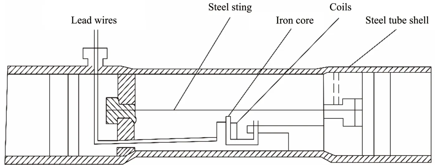
Figure 1 Structure diagram of the reinforcement stress meter
2.1.2 Configuration and applications
RSMs should be symmetrically arranged,with four at the calibration section and two at other sections,and fixed on the steel cage by welding or bolt connection(MOHURD,2014).Figure 2 illustrates the layout of RSMs in the reinforcement cage of a bored pile and view of a RSM in the field.Many factors affect the application of RSMs in engineering.Chenet al.(2018)provided a detailed review of the influencing factors such as creep and swell-shrink of concrete,elastic modulus,bending moment,and temperature.Chuet al.(2018)proposed corresponding solutions to a series of common problems arising from RSM applications,such as calibration,problems due to the discrepancy in the diameters of RSM and reinforcement in concrete,and errors caused by different installation methods.Huang(2017)attributed the failure and low survival rate of RSMs to issues with the signal wires and the sensor itself.Yin and Sun(2014)studied methods to improve the survival rate of RSMs with engineering examples.
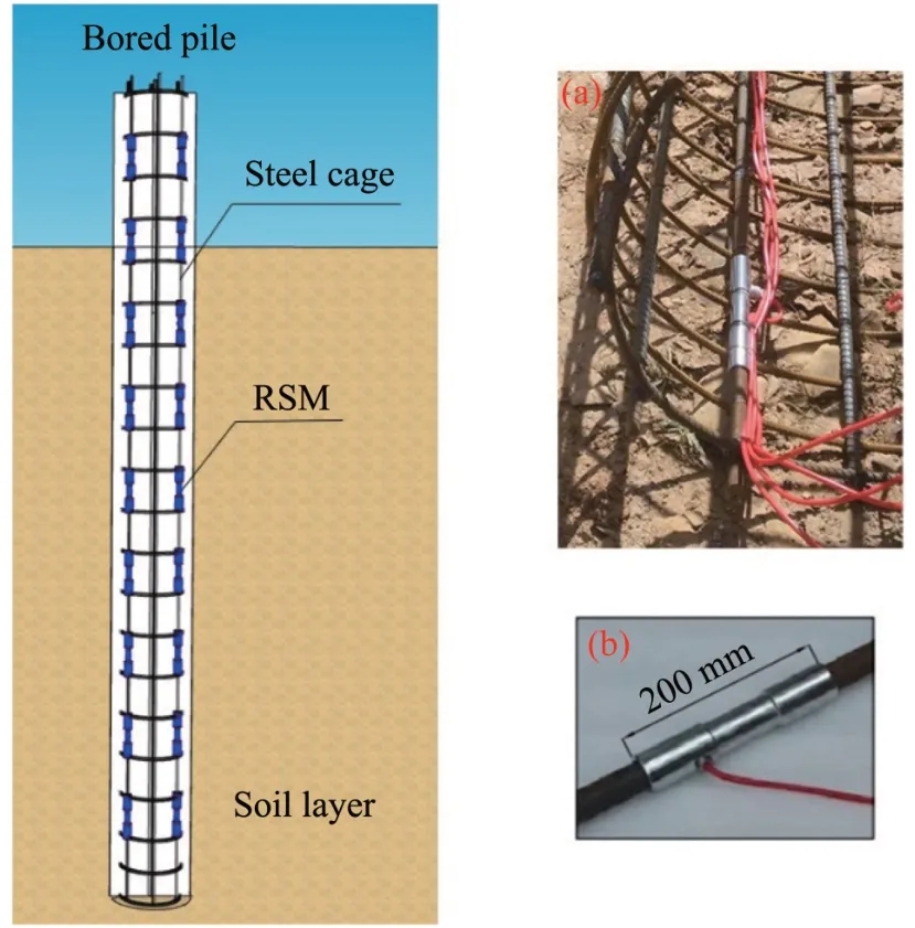
Figure 2 Layout and field installation of the reinforcement stress meter in a bored pile.(a)Field installation layout.(b)View of a reinforcement stress meter
RSMs have been applied in indoor and outdoor pile axial load tests,and the measurement results are accurate and can meet the requirements.For example,in the static load test of pile foundations,Liet al.(2003)measured the ultimate bearing capacity and side friction resistance of a pile by using RSMs.Xu and Cao(2006)and Zhuet al.(2013)arranged RSMs symmetrically at different depths along a pile to study the variation of negative skin friction of bored piles.Zhang(2005)embedded RSMs in a pile and analyzed the influence of different test methods on the loadbearing characteristics of a pile foundation,including shaft friction and end resistance.
2.1.3 Calculation methods
1)Pile axial load
The methods to evaluate pile axial load through RSM can be roughly divided into two categories:"fixed elastic modulus"and"variable elastic modulus"(Huang,2007).The"variable elastic modulus"method is more suitable for calculating pile axial load,because the elastic modulus of the concrete at different depths of the pile should be determined by the calibration relationship between the elastic modulus and the strain fitted at the section.After deleting the abnormal data,the average strain value for a pile section should be obtained.Then pile axial load at a specific section(MOHURD,2014)can be evaluated by
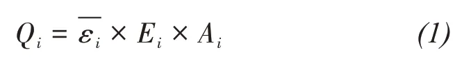
whereQiis the axial load at thei-th section of the pile shaft(N);is the average value of the strain at theith section;the impact of pile body creep should be eliminated during long-term monitoring;Eiis the elastic modulus of the pile body material at thei-th section(MPa);Aiis the cross-sectional area of the pile at thei-th section(mm2).
2)Pile shaft resistance
In general,the pile experiences downward displacement relative to the soil surrounding the pile,under vertical load,and the soil friction resistance acting on the pile side surface is upward,which is called the positive friction resistance.In special cases,when the ground around the pile settles relative to the pile,the direction of the friction resistance acting on the pile side is also downward,which is called the negative friction resistance(Zhang,2007;Shi,2015).The negative friction resistance will increase the axial load on the pile,hence its settlement and even its overall stability.The pile shaft resistance(MOHURD,2014)can be assessed by:
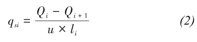
whereqsiis the friction resistance of the pile between thei-th section and thei+1-th section(Pa);QiandQi+1are the axial loads at thei-th section andi+1-th section of the pile shaft,respectively(N);iis the serial number of the pile side section,i=1,2,3,…,and arranged from small to large from the pile top;uis the perimeter of the pile(m);liis the pile length between thei-th section and the(i+1)-th section of the pile(m).
3)Pile tip resistance
Pile tip resistance(MOHURD,2014)is obtained by converting the pile tip axial load and can be described as:

whereqpis the pile tip resistance(Pa);Qnis the pile tip axial load(N);A0is the area of the pile tip(m2).
2.2 Strain gauge
2.2.1 Working principle
A strain gauge first converts the measured value into strain based on the resistance strain effect and then converts the strain into pile load(Xia and Li,1999).The basic working principle of strain gauges is that when an external load acts on the elastic element,it will deform and produce a corresponding strain or displacement,which is then transmitted to the attached resistance strain gauge,thereby causing its resistance to change(Huet al.,2018).According to the deformation compatibility conditions,the deformation of the strain gauge equals that of the concrete in the same section.The resistance variation is converted into the strain value by the gauge sensitivity coefficient provided by the manufacturer.The strain gauge is mainly composed of a sensitive grid,a substrate,an adhesive,a lead,and a cover sheet,as shown in Figure 3(NUAA,BUAA,1980).

Figure 3 Basic structure diagram of a strain gauge
2.2.2 Configuration and applications
The commonly used strain gauges can be divided into metal resistance strain gauges and semiconductor resistance strain gauges.Metal strain gauges are usually made of alloy materials,and most of them need to be attached to the pile surface with a special strong adhesive.Figure 4 depicts the configuration and field installation of strain gauges and its dimension.To improve the survival rate and measurement accuracy of strain gauges,Wang(1994),Lenget al.(2004),and Zhouet al.(2009)proposed detailed methods for the arrangement of strain gauges in pile model tests.Jon(2020)optimized strain gauge arrangement by error analysis in pile load testing and provided practical examples.Semiconductor resistance strain gauges are strain gauges with a semiconductor as sensitive grid material.They utilize the piezoresistive effect of semiconductor materials to achieve force-to-electric conversion and have the advantage of small size and high sensitivity(NUAA,BUAA,1980;Su,2011).One common issue of strain gauges is"zero drift"related to electrical measuring components in engineering applications.There are two main methods to deal with"zero drift".One is the hardware circuit compensation method,and the other is the software processing method.There are three main hardware circuit compensation methods.The first is to connect appropriate constant resistors in series and parallel on the bridge arm;the second is to slow down the change with resistors of opposite nature on the bridge arm;the third is to connect resistors in series and parallel outside the bridge(Sunet al.,2000).The software processing method uses computer compensation algorithms,such as curve fitting and tabular methods(Suet al.,2004).
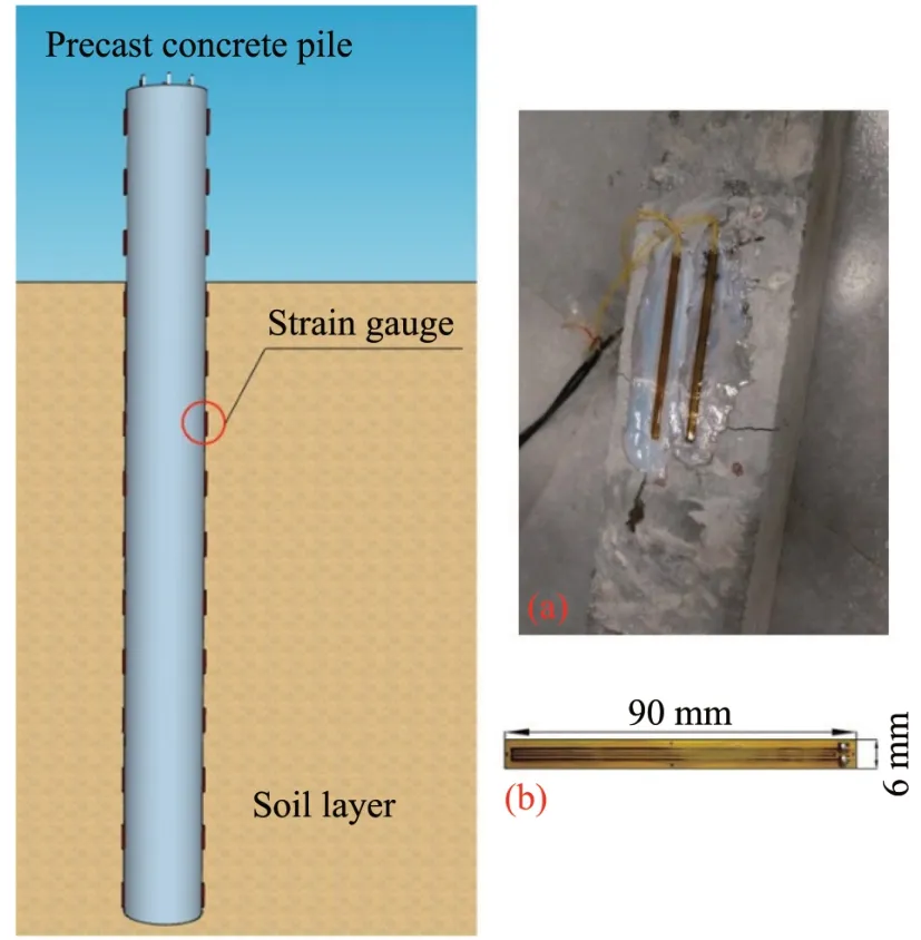
Figure 4 Layout and field installation of strain gauges in a precast concrete pile.(a)Layout and field installation.(b)Strain gauge dimensions
In pile axial load tests,the strain gauge should be installed appropriately depending on the pile type,While they can be directly attached to the steel pile surface,strain gauges should be tied or welded to the steel reinforcement cage for reinforced concrete piles(MOHURD,2014).In the static load test of PHC(prestressed high-strength concrete)piles,Luet al.(2006)embedded strain gauges at different sections along the pile to study the variation of the axial load and shaft resistance.Krasiński and Kusio(2015)attached strain gauges to the inside of a model pile,obtained reliable measurement of axial load variation and confirmed the effectiveness of strain gauges in indoor small model tests.Nafiulet al.(2019)installed strain gauges on the test piles to investigate load transfer mechanisms in different soil layers.They provided overall load-settlement curves and validated their results.Caiet al.(2019)attached strain gauges on the pile surface to study the variation of axial load and friction resistance and the effects of different test methods.
2.2.3 Calculation methods
The pile deformation under vertical load can be obtained by converting the resistance change in the strain gauge by the following equation(Xia and Li,1999)
whereεis the strain of the pile;Kis the sensitivity coefficient of the strain gauge;ΔRandRare the resistance change and the initial resistance value,respectively(Ω).
Pile load can be calculated as described in 2.1.3 once the strain is found.It is worth noting thatεshould be taken as the average value at the pile section.
2.3 Sliding micrometer
2.3.1 Working principle
The sliding micrometer was first developed in the Swiss Federal University of Technology in Zurich in the late 1970s(Kováriet al.,1979).Compared with the point method,the line method monitoring principle can achieve continuous measurement of deformation between two adjacent points on the measuring line and its measurement accuracy is greatly improved.This method assumes that the steel pipe,steel reinforcement cage,and concrete are poured together.The deformation between them is synchronized,and the displacement is also continuous(Heet al.,2007).Therefore,the strain of the measuring tube is the strain of the pile.The main body of the slide micrometer consists of a displacement sensor with a 1-m gauge length,a spherical probe at both ends,and an internal temperature sensor,as shown in Figure 5(Liet al.,2013).

Figure 5 Principle of the sliding micrometer
2.3.2 Configuration and applications
The sliding micrometer measures the displacement along the measuring line and can accurately measure the deformation of a pile section of several meters long.Its sensitivity can reach 0.001 mm/m,and the on-site measurement accuracy is less than or equal to±0.003 mm/m(Li and Huang,2000).The measurement marks on the measuring tube adopt the probe ball-cone positioning principle,which is marked by the spherical tip of the probe with an annular cone measurement,ensuring precise positioning of the probe for measurements up to one meter(Li and Huang,2000).Figure 6 depicts the layout of sliding micrometers and the details of sliding micrometers(Zhang,2018).
The advantages of the sliding micrometer over traditional point-mode monitoring sensors,such as the RSM and strain gauge,include higher continuity and testing accuracy,self-compensation for temperature,and the applicability to concrete piles where rebar meters cannot meet monitoring requirements(Ge,2012).The installation method of the slide micrometer should be selected according to pile types.For steel pipe piles,the measurement tube is welded on the pile wall at the measurement marks.For cast-in-place piles,the measurement tube will be tied and fixed on the main reinforcement.In addition,a measurement tube should be buried in the pile for a full length,and a test mark should be set every one meter(MOHURD,2014).It is worth noting that the sliding micrometer needs to be calibrated before and after each use to obtain the instrument's zero point and calibration coefficient.This requires manual measurement in the field,and automatic or wireless data transmission cannot be realized.
The sliding micrometer was first applied to pile deformation testing in 1982(Kovari and Amstad,1982).At present,sliding micrometers have been widely used in field surveys of foundations(Kovári and Peter,1983),dams(Donget al.,2006)and tunnels(Yeet al.,2017),as well as in the pile axial load testing and pile load transfer mechanism.Xu and Wu(1996)measured the pile axial strain by sliding micrometers and then analyzed pile ultimate bearing capacity and its load transfer properties.Chen(2005)introduced the theory and method of calculating the load transfer function of pile foundations using sliding micrometers and displacement coordination method and applied them in field studies.To obtain pile foundation design parameters,Wanget al.(2009)and Hanet al.(2014)used sliding micrometers to measure the variation of friction resistance of piles under vertical compressive load.
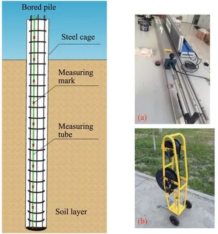
Figure 6 Layout and details of sliding micrometers in a bored pile.(a)Layout in a steel reinforcement bar cage and the connection of the probe to the cable.(b)Cable disc with a winch
2.3.3 Calculation methods
When the pile axial load is measured by sliding micrometers,the strain(MOHURD,2014)can be described as:
whereεis the strain value;eis the corrected instrument reading;e0is the corrected initial test instrument reading;e'is the instrument reading;z0is the instrument zero point;Kis the calibration coefficient.
The data measured by the sliding micrometer should consider the pile material's nonlinear stressstrain behavior and heterogeneity and the change in the pile cross-sectional area in the calculation process(Shiet al.,2003).Pile load can be calculated as described in 2.1.3.
2.4 Fiber optic strain sensor
The possibility that optical fiber could be used as a means of communication transmission was proposed in 1966(Kao and Hockham,1966).Afterward,the fiber optic sensing technology was first proposed by Méndezet al.(1990)and developed by Corning Inc.in the USA to monitor reinforced concrete structures and buildings.Fiber optic sensors can be divided into functional,non-functional,and light pickup sensors according to their purposes(Culshaw and Dakin,1997;Wang and Zhang,2002).Similar to the vibrating wire sensor,they generally need to be fixed to the reinforcement cage by welding or bolting.Fiber optic strain sensors not only have the advantages of small diameter,lightweight,high strength,good durability and bending performance,and good coordination with the measured object but also have high sensitivity and accuracy.In addition,as the optical fiber is flexible,fiber optic sensors can be made into different shapes depending on project needs.They have been widely used in civil engineering(Jiang and He,2002).Two types of fiber optic sensors are typically applied in engineering:fiber Bragg grating(FBG)and Brillouin optical time-domain reflectometer(BOTDR)and are introduced next.
2.4.1 Fiber Bragg grating
FBG sensor is a wavelength-modulated fiber optic sensor for nonlinear action.It was first fabricated by Hillet al.(1978)to study the photosensitivity of optical fibers.The working principle of FBG is that the change in temperature,stress,and other physical variables of the external environment causes variation in the structural characteristics of FBG,leading to drift in the FBG reflection spectrum(Huet al.,2018).Thus,the change in the corresponding external physical variables can be obtained by detecting the drift of the center wavelength of the FBG reflection spectrum.The strain measurement accuracy of FBG is about±1με(Zhou and Liu,2005;Shen,2010),and Figure 7 illustrates its structure diagram(Li,2009;Huet al.,2018).In the figure,I is the signal intensity,λis the wavelength,andλBis the center wavelength of the reflected light.
However,due to the fragile material of FBG and the cross-sensitive characteristics of temperature and strain,it faces the problems such as encapsulation protection and temperature compensation in field applications(Weiet al.,2009).FBG sensors can be divided into patch types and embedded types according to different test methods.Patch types can be installed on the pile surface by pasting or spot welding to monitor the deformation,while embedded types are tied to the main reinforcement to monitor the deformation inside the pile.Its layout and field installation methods are shown in Figure 8.
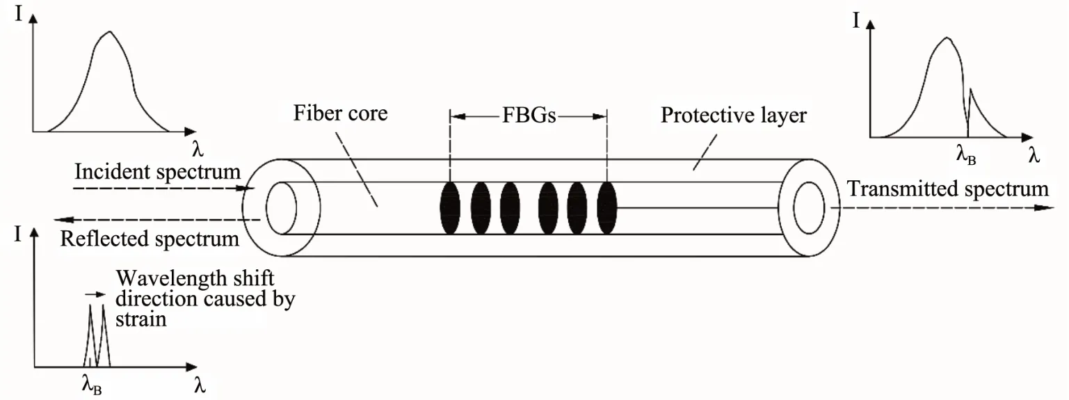
Figure 7 Structure diagram of fiber Bragg grating
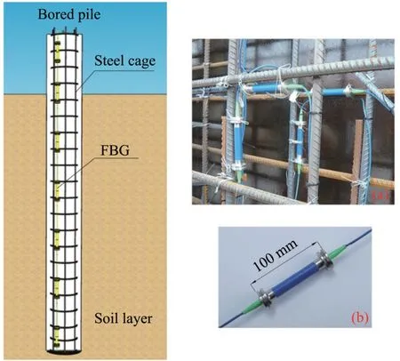
Figure 8 Layout and installation method of fiber Bragg grating sensors in a bored pile.(a)Field installation layout.(b)View of fiber Bragg grating sensors
FBG was initially applied to the health monitoring of bridge structures.Due to its high measurement accuracy and broad applicability,it was later widely used in other projects such as dams(Zhuet al.,2008),tunnels(Zhao and Qiu,2007),and slope deformation(Liet al.,2008).Ohet al.(2000)and Baldwinet al.(2001)compared FBG with strain gages by indoor and field tests and demonstrated the possibility of FBG for studying pile load transfer mechanisms.Leeet al.(2004)and Chriset al.(2004)monitored the structure health by measuring the strain of the pile through FBG.Wanget al.(2021)studied the effect of different pile diameters on the static load transfer by embedding FBG in a pile.
The variation in the center wavelength of the FBG due to strain and temperature change can be described as(Zhuet al.,2010)
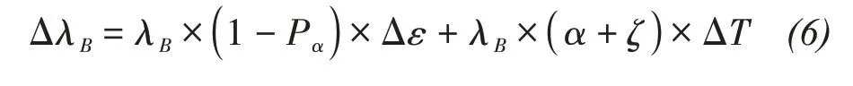
where ΔλBis the variation in central wavelength;Pαis the photoelastic coefficient of grating,0.22 for standard single-mode fiber;Δεis the variation in strain;αis the coefficient of thermal expansion;ζis the thermal-optical coefficient;ΔTis the variation in temperature(°C).
When temperature compensation is used,the effect of temperature on the wavelength shift in the above equation can be ignored and is only strain-dependent.The variation in strain can be evaluated as(Zhouet al.,2020)

whereηis the coefficient depending on the FBG package quality.Its value ranges between 0 and 1,with 1 indicating the best package quality.Pile load can be calculated as described in 2.1.3.
2.4.2 Brillouin optical time-domain reflectometer
The sensing mechanism of BOTDR was first proposed by Kurashimaet al.(1993).The working principle of BOTDR is based on the Brillouin scattering effect.Namely,a change in strain or temperature somewhere along the optical fiber will induce variation in the frequency of the scattered Brillouin light(Cuiet al.,2004).Then,based on the pre-calibrated Brillouin frequency shift coefficients for strain and temperature,the variation in strain or temperature at a particular location along the optical fiber can be calculated.Figure 9 illustrates its measurement schematic(Ohnoet al.,2001).
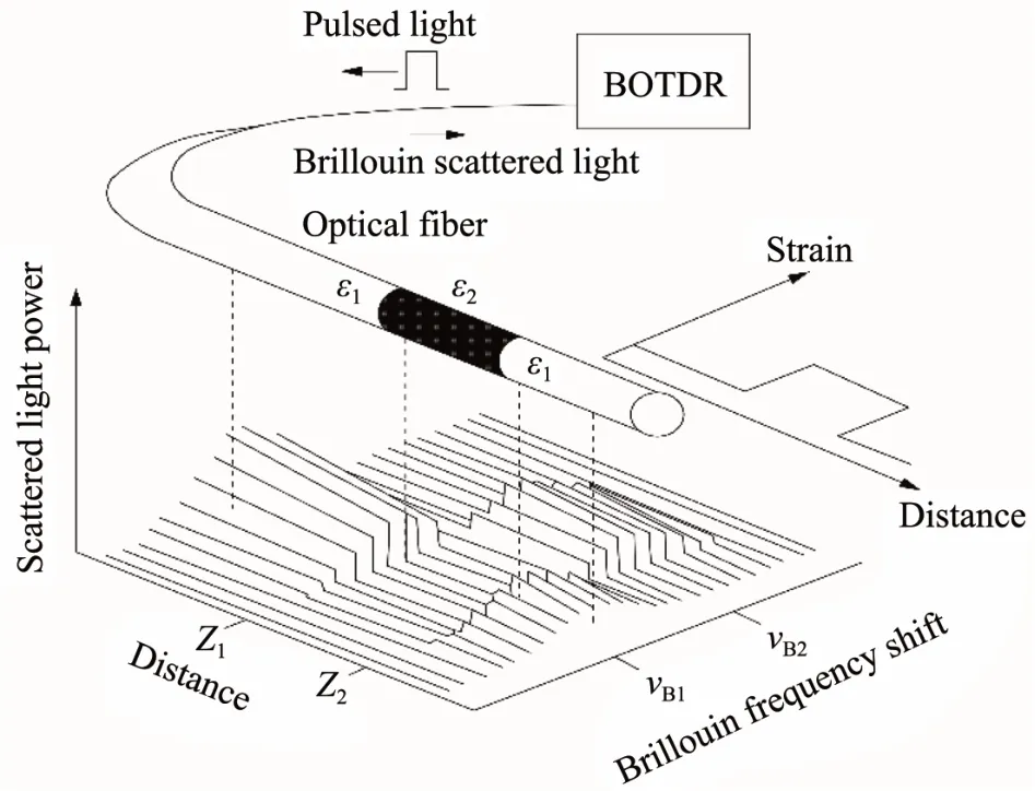
Figure 9 Measurement schematic of Brillouin optical time-domain reflectometer
BOTDR is a fully distributed fiber optic sensor(DFOS)that can measure the strain distribution along the optical fiber.Its strain accuracy varies depending on the detecting instrument and measurement distance and can generally reach±30με(Luet al.,2014).Moreover,the nominal maximum measurement distance of BOTDR can reach 80 km,with practical measurement distances up to 60 km,which can meet the demand of ultra-long distance monitoring of temperature field and large-scale structural deformation in engineering(Qin and Gu,2008;Luet al.,2014).It is worth noting that Baoet al.(2020)provided a detailed review of the recent development of BOTDR at home and abroad in five aspects,including basic structure,spatial resolution,measurement distance and accuracy,measurement time,and temperature and strain cross-sensitivity.
BOTDR has the advantages of high measurement accuracy,wide measurement range,and easy installation.Figure 10 shows its layout and installation in a reinforcement cage of a bored pile(Gaoet al.,2019).It can measure both temperature and strain and is widely used in pile strain monitoring(Liuet al.,2012),structure health surveillance(Zhanget al.,2003;Shiet al.,2004),and slope deformation tracking(Liu,2011).For instance,Klaret al.(2006)applied BOTDR to measure the strain of piles and demonstrated its advantages and disadvantages.Piao(2008)and Piaoet al.(2010)installed BOTDR in test piles for detecting the variation patterns of axial load,frictional resistance,and tip resistance and verified the feasibility of its application to monitoring bored piles by engineering examples.Battistaet al.(2016)combined the DFOS system with BOTDR to obtain complete strain and temperature profiles along the length of the piles.Pelecanos and Soga(2018)measured the strain along the length of a pile by BOTDR and analyzed the loadtransfer mechanisms.
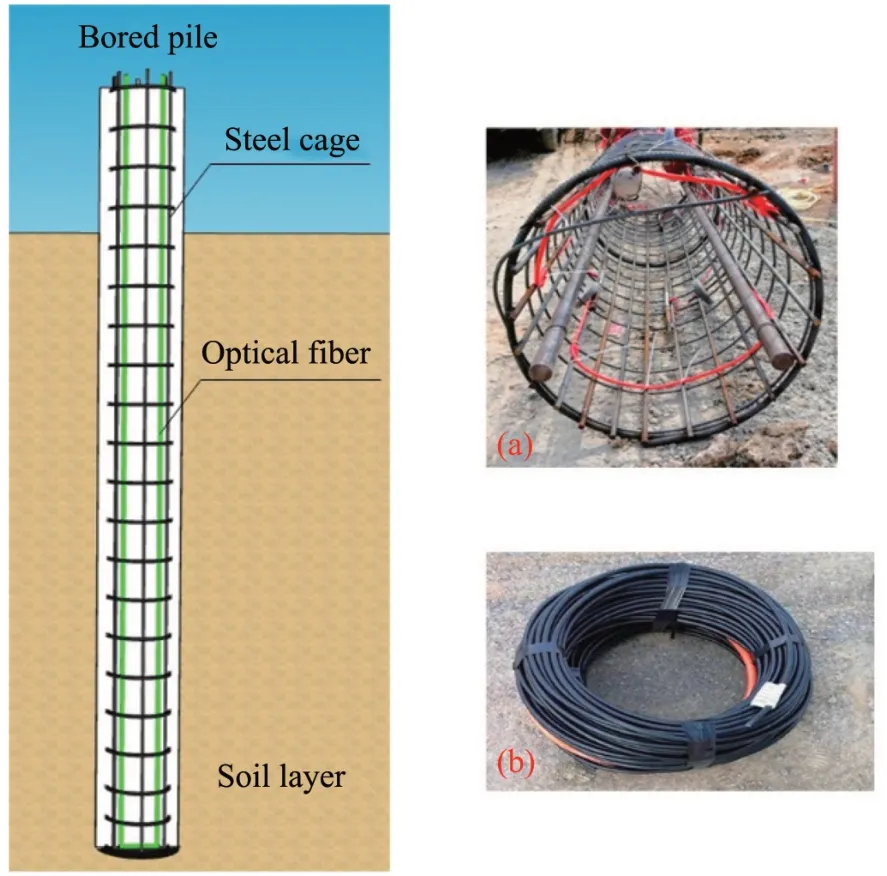
Figure 10 Layout and field installation of Brillouin optical time-domain reflectometer in a bored pile.(a)Installation in a reinforcement cage.(b)Optical fiber cable
The drift of the Brillouin frequency can be expressed as a linear function of the strain in the fiber(Horiguchi and Kurashima,1989),and the strain from BOTDR can be described as:
or

whereνB(ε)is the Brillouin frequency drift at a strain ofεin the optical fiber,which can be measured by a BOTDR;νB(0)is the Brillouin frequency drift when the strain is 0;is the strain coefficient of Brillouin frequency shift to be calibrated.It is about 0.05 MHz/μεfor a standard single-mode fiber with a zero-dispersion wavelength of 1.55μm window(Kurashima,1997).
A tensile test must be performed on the optical fiber before the strain measurement to determineνB(0)and.Since the Brillouin frequency shiftνBis related to temperature and strain,the above equation needs to be corrected for temperature compensation(Ohnoet al.,2001).At a temperature change ofTand a strain ofε,the drift of the Brillouin frequency(Ohnoet al.,2001)can be described as:
3 Applicability in cold regions
The four testing methods are mature for pile axial load tests in non-frozen soil areas and have been widely adopted.However,their applications in permafrost are relatively scarce,especially sliding micrometers and fiber optic strain sensors.Compared with non-frozen soils,the lower ground temperature,larger daily and annual temperature variation,and freeze-thaw problems in permafrost areas may cause instability or even failure in sensor measurements,leading to errors in the calculation of pile axial load.At present,the procedure of pile load transfer is not clearly defined for cold regions,resulting in a conservative design.Such examples include large diameter and long single piles commonly found in highway and railroad construction,resulting in unnecessary wastes in human,material and financial resources.It is urgent to find a method that can accurately monitor the internal force change in pile foundations in cold regions.The current status and applicability of the four methods in cold regions are discussed below.
3.1 Vibrating wire sensor
There are many problems with the RSM when applied in cold regions,such as the calibration of the initial frequency(Xieet al.,2013),temperature changes,and variation in the pile-frozen soil interface,which can directly affect its measurement accuracy.There have been some studies on the field test of RSM in the frozen ground,and it can provide good data and reference.But there are fewer applications in indoor model pile tests at low-temperature conditions.Lu and Sun(1986)used a custom-made RSM in a seasonally frozen soil area to measure the change of tangential frost heaving force on a pile under freeze and thaw conditions and accounted for temperature correction in the calculation.In an artificial freezing project,Jiang(2013)placed RSMs on the outside of the frozen wall to ensure the safety of the wellbore and used a pressure box to monitor the force between the frozen wall and the wellbore in real time.Sun et al.(2007)placed RSMs along different pile sections to study the load transfer mechanism and the distribution and magnitude of frost heaving force around piles in cold regions.The test results were satisfactory and provided a reference for the design and construction of pile foundations in cold regions.The RSM has the advantages of vibration resistance,simple structure and embedding process,and low cost.It has been used for a long time in China and has been verified in a large number of engineering tests.In summary,RSM can be suitable for monitoring under complex environmental conditions in cold regions.It should be noted that when applied in cold regions,the RSM's initial frequency should be measured at the construction site to ensure acurate measurement results(Liet al.,2003;Chuet al.,2018).
Due to the significant temperature change in frozen soil areas,the temperature effect should be considered in the calculation(Li,2014).The pile axial load at a certain section can be described as:
and
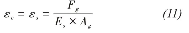
whereQiis the axial load at the i-th section of the pile(N);Fs,FcandFgare the axial load of steel reinforcement,concrete,and RSM,respectively(N);σcandσsare the stresses of concrete and steel reinforcement,respectively(MPa);Ac,AsandAgare the cross-sectional areas of concrete,steel reinforcement,and RSM,respectively(mm2);Esis the elastic modulus of the steel reinforcement(MPa);fcmis the average compressive strength of concrete(MPa);εsandεcare the strain values of steel reinforcement and concrete,respectively;εTis the strain caused by the temperature effect.
3.2 Strain gauge
The strain gauge is usually affixed directly to the pile surface.When applied in frozen soil areas,the change in temperature and the choice of affixing method significantly impact the measurement accuracy.On the one hand,the temperature change will cause the strain sensor to deform and change its resistance value.On the other hand,the different linear expansion coefficients of concrete and strain gauge sensitive grid materials will cause additional strain(Shuai,2017).In addition,the freeze-thaw cycling will impact the mechanical properties of the soil,which further affects the measurement accuracy of the strain sensors.Therefore,it is necessary to perform temperature compensation on the strain sensors in cold regions.Commonly used methods are the bridge compensation method and strain gauge self-compensation method.The bridge compensation method is to connect a single-arm Wheatstone bridge in series in the thermocouple temperature measurement system.The output voltage of this bridge changes with the temperature of the cold end of the thermocouple.But it is necessary to ensure that the working and compensation pieces have the same temperature(Huet al.1996;Huet al.,2018).The automatic compensation temperature strain gauge uses a special strain gauge that allows for self-compensation of temperature and it needs to be customized depending on the different materials(Shuai,2017).
Zhanget al.(1995)applied strain gauges to measure the frozen soil deformation in a low-temperature environment for the first time in China.The test results were accurate,but attention should be paid to selecting suitable attachment methods.Shuai(2017)glued strain gauges on model piles under artificial freezing conditions to study the load distribution along the pile and analyzed the feasibility of applying the strain gauge on piles in frozen soil areas.He also proposed a method to eliminate the influence of temperature changes;that is to install two identical strain gauges symmetrically at the same section of the pile.Chen(2011),Zhu(2011),and Luet al.(2017)measured the variation of pile strain by attaching strain gauges on the steel reinforcement inside the pile in the frozen soil area and then studied the mechanical properties of the pile.
The strain gauge has the advantages of small size,simple structure,low cost,simple operation method,and suitability for small gauge length and large deformation measurement,making it a good option for application in frozen ground regions.However,due to the complex environmental changes and large temperature changes in cold regions,effective measures should be taken during the construction process to ensure the survival rate and measurement accuracy of strain gauges to maintain its long-term stability.
3.3 Sliding micrometer
The sliding micrometer was introduced by the Institute of Rock and Soil Mechanics,Chinese Academy of Sciences,in 1984.Li(1988)summarized its fundamental principles,technical parameters,instrument structure,and engineering application examples.However,the application of the sliding micrometer in China is still immature.The manual operation requirement makes it less applicable in cold regions.No literature related to its application in domestic permafrost zones has been retrieved.Sunet al.(2019)tested and analyzed the bearing performance of pile foundations using a sliding micrometer in Changchun,China.The average temperature during the test was about-2 °C,and the test results were accurate.This indicates that the sliding micrometer could operate in the frozen soil area.At present,the application of the sliding micrometer in non-frozen soil areas has been verified by various studies.There are many descriptions about its application in engineering in section 2.3.1,and the overall test results are satisfactory(Wanget al.,2010).However,the application in cold regions needs to be further verified.
The sliding micrometer is used to obtain the relative deformation by sequential measurements between two marks arranged before the construction.It requires manual calibration with a portable calibration cylinder before and after the measurement.However,most pile foundation projects in frozen ground regions are in harsh environments and unhabitable areas.Manual measurement can be carried out during construction,but it is not feasible to repeat after the construction is finished.Therefore,the method is only suitable for short-term measurement in pile foundation monitoring in frozen soil areas until the sliding micrometer realizes automatic measurement and longdistance wireless transmission.
3.4 Fiber optic strain sensor
FBG and BOTDR have different applicability in the frozen soil region.In recent years,the application of FBG in the monitoring and experiment of frozen soil engineering has gradually increased.Zhou(2020)buried the FBG in the indoor roadbed model to study its applicability and measurement accuracy in monitoring roadbed deformation in the seasonally frozen ground region.Pang(2016)arranged FBG implanted beams at the road sections in the seasonally frozen soil area to study the roadbed stability by monitoring its deformation under the vehicle load and proposed two different ways of embedding the FBG sensors in the road.Menget al.(2020)proposed an FBG-based embedded cantilever sensing beam for roadbed deformation monitoring in the seasonally frozen ground.They installed a PVC pipe with FBG attached on the outside in a test section horizontally,and the test data were combined with the continuous medium mechanics for calculation.Three years of field monitoring test data verified the feasibility of the method.When FBG is used in cold regions,there is no need for continuous monitoring because it outputs an absolute strain.Therefore,a portion of the grating can be used as a temperature sensor to account for the effects of large temperature variation on the test results(Yang,2012).
The BOTDR can obtain the axial strain at any point along the optical fiber,whether it is fixed on the surface of or embedded in the pile,the strain distribution along the corresponding pile can be measured.Its temperature correction formula can also meet the characteristics of the large temperature variation in the frozen ground region(Zhanget al.,2003).Yuan(2015)placed a BOTDR inside a steel pipe installed in a borehole to study the deformation mechanism of the frozen wall during freezing.It also showed that BOTDR could meet the measurement and accuracy requirements under low-temperature conditions.Jianget al.(2016)buried a BOTDR in a highway in seasonally frozen regions to assess the health of the subgrade structure by monitoring its vertical and horizontal deformation.The measurement results can accurately reflect the structural characteristics of the highway.In general,there are few domestic studies on the application of the BOTDR to engineering monitoring in cold regions,and its application needs to be further verified.Table 1 summarizes the key technical parameters,applicability in cold regions,advantages and disadvantages of the four test pile axial load test methods.
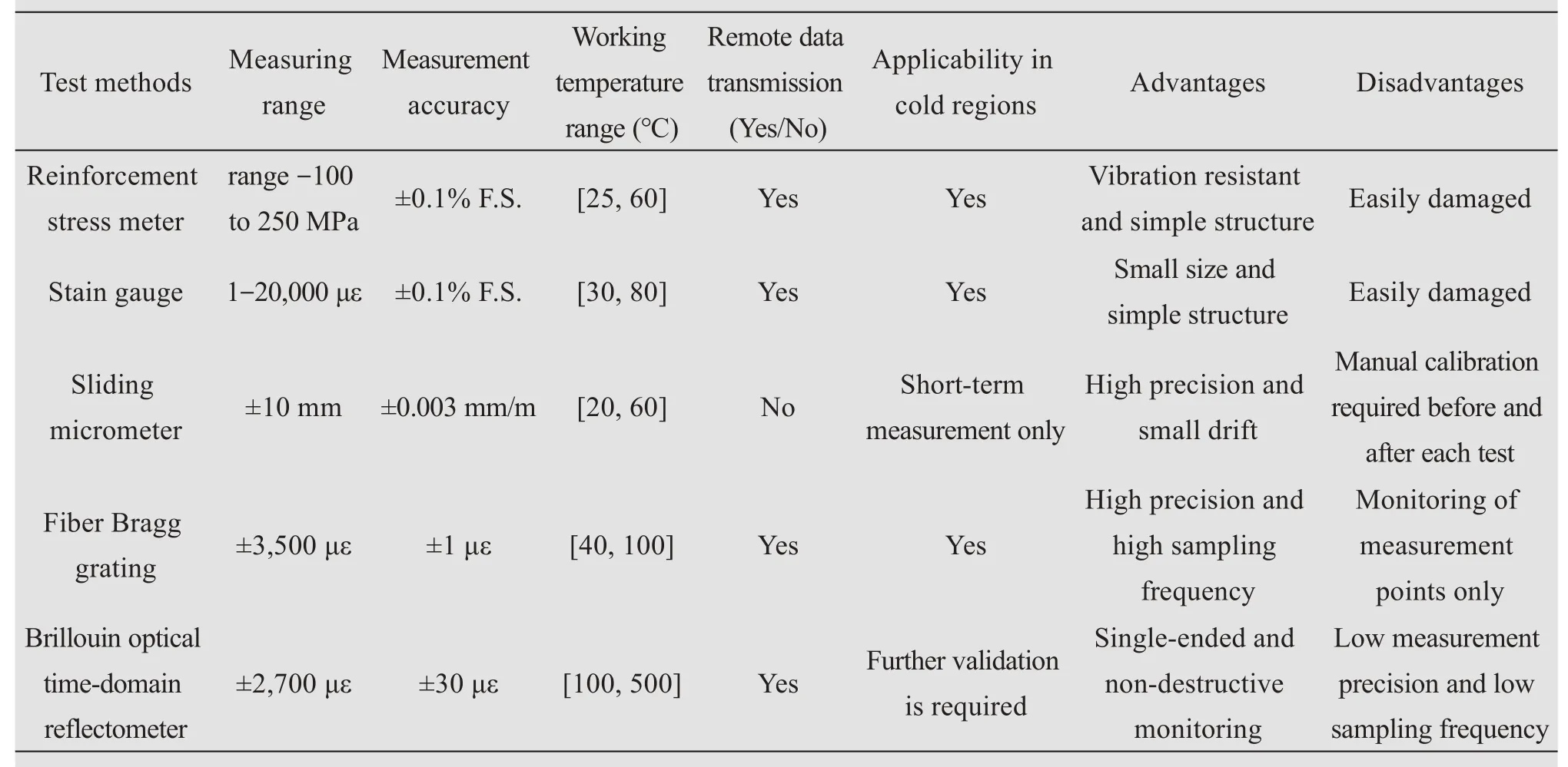
Table 1 Summary of the test methods
4 Conclusions and Prospect
There are in-depth theoretical studies and analyses of pile behavior,but the corresponding testing and monitoring technologies are relatively lagging and cannot meet the demand for verification of theoretical results(Wang,2011).This paper summarizes the different methods applied to pile axial load assessment,including their working principles,layout methods,and advantages,and analyzes the applicability of these methods in frozen ground regions.
(1)The reinforcement stress meter and strain gauge have simple structure and construction methods,low cost,and are mature technologies for pile axial load tests.In contrast,the sliding micrometer has the advantage of good continuity,high accuracy,and temperature self-compensation,and the fiber optic strain sensor has high strength,good durability and bending performance,and good compliance with the study object.
(2)The reinforcement stress meter and strain gauge are suitable for pile axial load testing in cold regions,but effective measures should be taken to ensure its survival rate and eliminate the impact of temperature changes during construction.The sliding micrometer requires manual calibration before and after the measurement,which is only suitable for shortterm monitoring in cold regions.The FBG strain sensor can meet the monitoring requirements,but the BOTDR needs to be further verified.Specifically,attention should be paid to the cross-sensitivity between temperature and strain.
The four pile axial load testing methods have different advantages and disadvantages.Various testing techniques should be combined according to the onsite construction situation in engineering applications,such as RSM-strain gauge,RSM-sliding micrometer,and FBG-BOTDR.On the one hand,different sensors can complement each other to eliminate the shortcomings.On the other hand,they can provide results for mutual verification.
Acknowledgments:
This study was supported by the Strategic Priority Research Program of the Chinese Academy of Science(XDA20020102),the Science and Technology Project of State Grid Corporation of China(SGQHDKYOSBJS201600077),the Natural Science Foundation of China(41101065),and the State Key Laboratory of Frozen Soils Engineering Foundation(SKLFSEZT-34).
 Sciences in Cold and Arid Regions2022年4期
- Sciences in Cold and Arid Regions的其它文章
- The influence of the underpassing frozen connecting passage on the deformation of the existing tunnel
- Influence of freeze tube deviation on the development of frozen wall during long cross-passage construction
- Thermal-Hydro-Mechanical coupled analysis of unsaturated frost susceptible soils
- Frozen curtain characteristics during excavation of submerged shallow tunnel using Freeze-Sealing Pipe-Roof method
- Application of automated cone penetrometer for railway investigation using correlations with DCPI and Deflection Modulus
- Triaxial test on glass beads simulating coarse-grained soil