Interval Type-2 Fuzzy Hierarchical Adaptive Cruise Following-Control for Intelligent Vehicles
Hong Mo, Yinghui Meng, Fei-Yue Wang,,, and Dongrui Wu
Abstract—Intelligent vehicles can effectively improve traffic congestion and road traffic safety. Adaptive cruise followingcontrol (ACFC) is a vital part of intelligent vehicles. In this paper,a new hierarchical vehicle-following control strategy is presented by synthesizing the variable time headway model, type-2 fuzzy control, feedforward + fuzzy proportion integration (PI) feedback(F+FPIF) control, and inverse longitudinal dynamics model of vehicles. Firstly, a traditional variable time headway model is improved considering the acceleration of the lead car. Secondly,an interval type-2 fuzzy logic controller (IT2 FLC) is designed for the upper structure of the ACFC system to simulate the driver’s operating habits. To reduce the nonlinear influence and improve the tracking accuracy for the desired acceleration, the control strategy of F+FPIF is given for the lower control structure.Thirdly, the lower control method proposed in this paper is compared with the fuzzy PI control and the traditional method(no lower controller for tracking desired acceleration) separately.Meanwhile, the proportion integration differentiation (PID),linear quadratic regulator (LQR), subsection function control(SFC) and type-1 fuzzy logic control (T1 FLC) are respectively compared with the IT2 FLC in control performance under different scenes. Finally, the simulation results show the effectiveness of IT2 FLC for the upper structure and F+FPIF control for the lower structure.
I. INTRODUCTION
NOWADAYS, urban populations and vehicles are increasing rapidly. In 2021, the Traffic Administration of the Ministry of Public Security released a report that the number of motor vehicles in China in 2020 had reached 372 million[1]. The vehicle brings great convenience to the public, but at the same time, it also causes a series of serious social problems, where traffic safety is particularly prominent. From the WHO’s State of Global Road Safety Report in 2018, road traffic fatalities continue to rise, with 1.35 million deaths a year, being the leading cause of death for people aged 5 to 29[2]. It is estimated that about 90% of traffic accidents are caused by human error, such as fatigued driving, drunk driving, distractions, misjudgment, and lack of safety awareness[3]. In recent years, to reduce the incidence of traffic accidents, many research works in the world focus on the technologies that can assist drivers, such as advanced driver assistance systems (ADAS) [4]-[6], autonomous-driving systems [7], [8]. Among which, adaptive cruise control (ACC)is one of the most representative technologies [9], [10]. A traditional ACC system is generally divided into cruise control and adaptive cruise following-control (ACFC) (or safe distance keeping control). The hierarchical structure of the ACC system is as Fig. 1.
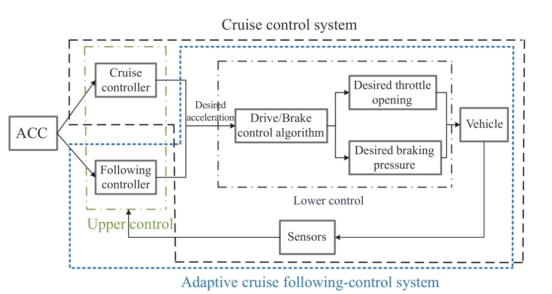
Fig. 1. Hierarchical structure of the traditional ACC system.
The principle of cruise control is simple and the corresponding control algorithm is mature. The ACFC is relatively complex, which requires that the speed of the main vehicle approaches that of the preceding vehicle and the actual distance between the two vehicles is close to the desired safe distance. The hierarchical control includes upper and lower control. The upper control is used to obtain desired acceleration and the lower control is for solving desired throttle opening and braking pressure according to desired acceleration,where the lower control method is usually the inverse longitudinal dynamics model of vehicles.
The current research for ACFC mainly focuses on the design of the upper controller. In fact, the vehicle system is a complex large-scale system, and the inverse longitudinal dynamics model of vehicles is established based on reasonable assumptions, which can not accurately reflect the actual vehicle system. Moreover, the parameters of the actual vehicle model are easily affected by external environmental factors.Those will lead to a large error between the actual output acceleration and the desired acceleration if the lower control only uses the inverse longitudinal dynamic model of vehicles,which will result in reduced control accuracy and even ride discomfort. To this end, a controller for tracking desired acceleration based on feedforward + fuzzy proportion integration (PI) feedback (F+FPIF) is proposed for the lower control structure, where the feedforward control is to improve the response speed of the system and fuzzy PI feedback control is to improve the tracking accuracy of the system to desired acceleration.
On the other hand, the upper control strategies for the ACFC system have been studied by many researchers at present. For example, based on the bode ideal transfer function, the proportion integration differentiation (PID)controller which uses the ant lion optimization algorithm to adjust the parameters is designed to improve the dynamic performance indicators of the system [11]. In [12], a linear quadratic regulator (LQR) controller considering reaction headway is given to deal with complex traffic environment information and achieve the purpose of safe and comfortable driving. A sliding mode controller is designed in [13], which uses the particle swarm optimization algorithm to optimize the parameters, and the results show its good control performance on car-following. A fuzzy logic controller by the virtual carfollowing simulation to adjust its parameters is designed and achieves a good control effect [14]. Liet al. [15] use a model predictive controller (MPC) to reduce fuel consumption and improve tracking accuracy. A driver model based on the feedback-error learning scheme is put forward, which indicates that the control performance is superior to manual driving [16]. A multi-model method is studied in [17], which proves that it is superior to the single model method in simulating individual driving styles. In addition, to improve the ability of the ACC system to coordinate various goals and adapt to a complex and changeable driving environment,Yanget al. [18] design a multi-objective control algorithm.Considering the dynamic response of the automobile to the desired acceleration, a motion model, which can make the errors of the distance and speed converge synchronously and reduce the time for the main car to follow the lead car steadily, is established [19]. For mixed traffic flows, Luet al.[20] study an electric driving model and prove the energy consumption is superior to the existing ACC. For driving on expressways, a control strategy that can change the driving behavior of ACC vehicles in real-time according to traffic conditions is proposed [21].
Although there are many studies for upper control of ACFC,LQR, MPC, PID and fuzzy control are commonly used research methods. The LQR and MPC have good control effects for specific systems, but the solution is very complex. When the model changes or the system becomes more complex, the control effect will be reduced or hard to implement. PID is easy to operate and has good control ability for linear systems,however, the control effect is less than satisfactory for complex nonlinear systems. Fuzzy control has a good control effect for the nonlinear, time-varying and hysteresis systems.To a certain extent, it can simulate a driver’s manipulation and show characteristics of human thinking. It is not necessary to establish an accurate mathematical model for the controlled system and has strong adaptability to nonlinear cruise control systems. Therefore, many scholars have applied it to the lateral and longitudinal control of autonomous vehicles and achieved good control effects [22], [23]. However, the fuzzy control is based on type-1 fuzzy sets (T1 FSs), which has some limitations in dealing with uncertain problems [24].
In 1975, Zadeh [25] proposed type-2 fuzzy sets (T2 FSs).Different from T1 FSs, T2 FSs can synthesize the membership functions given by different people, give more freedom to define the membership functions, and can better solve the problems with fuzziness [26]-[30]. At present, the T2 FSs and type-2 fuzzy logic systems (T2 FLSs) have been widely used,for instance, traffic planning and control [31]-[34], medical diagnosis and control [35]-[39], mobile robot control[40]-[42], fault diagnosis [43], [44], power load forecasting[45], [46], power system control [47], [48], evaluation[49]-[51], decision [52], [53], wind power system [54]-[56],unmanned vehicles [57]-[59], and others [60]-[63]. These validate that the T2 FSs and T2 FLS have better performance than the corresponding T1 FSs and type-1 fuzzy logic system(T1 FLS) in many applications.
Wuet al. [64] summarize some advantages of T2 FLS compared with T1 FLS: 1) T2 FSs can model intra-individual uncertainty and inter-individual uncertainty at the same time,while T1 FSs can only model intra-individual uncertainty. 2)T2 FLS has the characteristics of smoother control surfaces near the steady-state (error or variation rate of error is 0). 3)To achieve the same function, T2 FLS needs fewer control rules than T1 FLS.
However, the computation of generalized T2 FS (GT2 FS)is particularly complex. Since the secondary membership degree of interval T2 FSs (IT2 FSs) is 1 and the calculation is relatively simple, the interval T2 FLS (IT2 FLS) is widely used in the engineering field.
In summary, the F+FPIF and IT2 FLS are used as the lower and upper controllers of the ACFC system, respectively. The main contributions of the paper are elaborated below:
1) An improved variable time headway model, which comprehensively considers the influence of the speed of the main vehicle, the relative speed between the main vehicle and the lead vehicle, and the acceleration of the lead vehicle on car-following safety distance, is given and used as the safe distance model for vehicle-following.
2) An interval type-2 fuzzy logic controller (IT2 FLC),which takes relative distance difference and relative speed as the input variables and the desired acceleration as the output variable, is designed for the upper control structure to simulate the driver’s operating habits.
3) A control strategy based on F+FPIF is provided for the lower control structure, to improve the tracking speed and accuracy of the system to the desired acceleration.
The rest of the paper is organized as follows: Section II introduces the T2 FSs and T2 FLS, and analyses the inverse longitudinal dynamics model of vehicles. The improved safe distance model is analyzed in Section III. IT2 FLC and fuzzy PI controller are designed in Section IV. Section V is the simulation and analysis of the results. Section VI summarizes the paper.
II. PRELIMINARY
A. Type-2 Fuzzy Sets
LetI=[0,1],C(II) be a set of all the nonempty close subsets ofI. A T2 FS onXis defined as follows [65]:
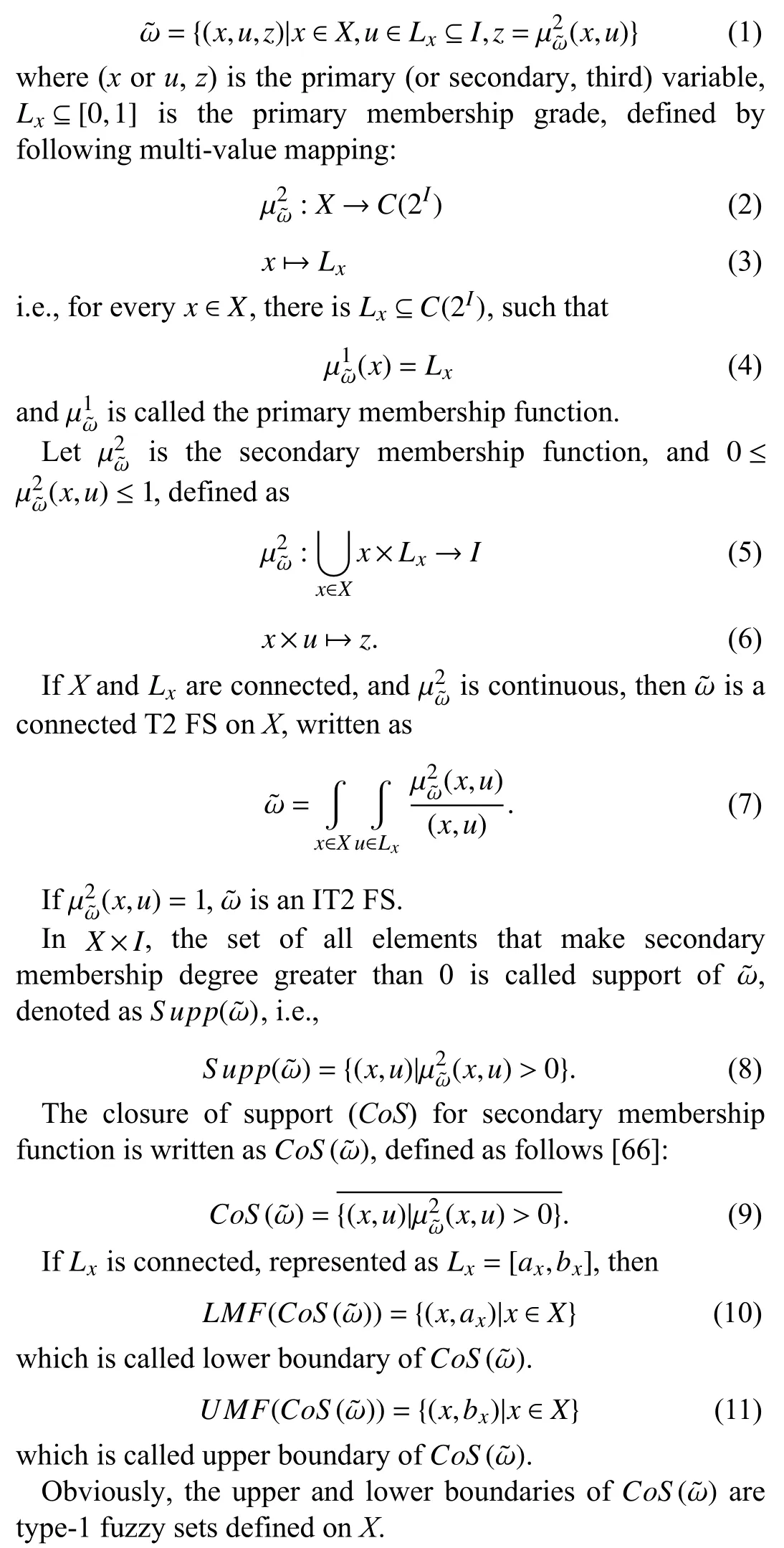
B. Type-2 Fuzzy Logic System
The T2 FLS mainly includes five parts: fuzzifier, inference engine, rule base, type-reduction, and defuzzifier. Its structure is as Fig. 2.
Different from T1 FLS, T2 FLS adds a type-reduction module, and the module is also the focus and difficulty of T2 FLS. The other modules can refer to [67]-[70].
The main purpose of type-reduction is to convert T2 FS into T1 FS, which is equivalent to finding the centroid of the T2 FS. Some methods, such as centroid type-reduction, center-ofsums type-reduction, height type-reduction and center-of-sets type-reduction, are widely used [71]-[75].
The main steps for calculating the centroid of T2 FS are as follows:
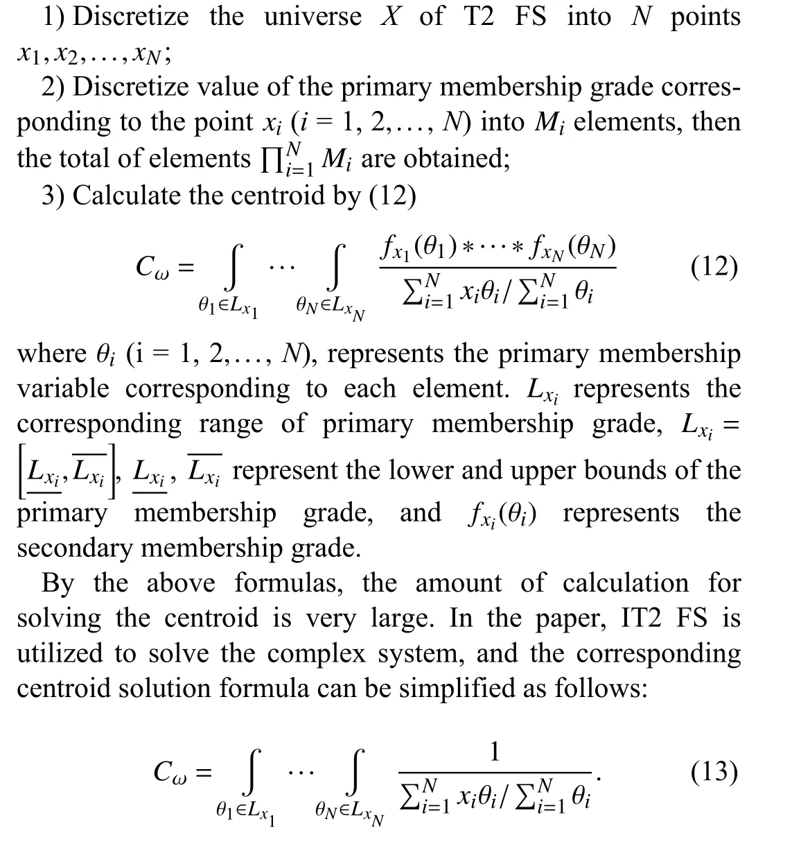
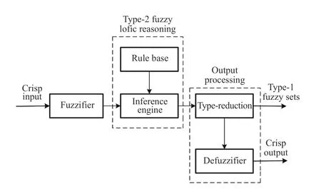
Fig. 2. Structure of T2 FLS.
C. Inverse Longitudinal Dynamics Model of Vehicles
The inverse longitudinal dynamics model of vehicles is to solve the desired throttle opening and braking pressure according to desired acceleration. The structure is as Fig. 3.
1) Driving Model:Normally, when the vehicle is driving,the braking force is zero, and when the vehicle is braking, the driving force is zero.

Fig. 3. Structure of inverse longitudinal dynamics model of vehicles.
If the vehicle is driving on a flat road, the motion equations are expressed as follows [76]:
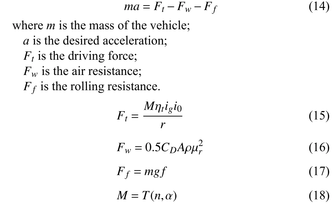
whereMis the output torque of the engine;
ηtis the efficiency of the transmission system;
igis the transmission ratio of the transmission;
i0is the transmission ratio of the final reducer;
ris the wheel radius;
CDis the air drag coefficient;
Ais the windshield area;
ρis the air density;
μris the relative speed of the vehicle and the wind;
gis the acceleration of gravity;
fis the coefficient of rolling resistance;
nis the rotation speed of the engine;
αis the throttle opening;
Tis the torsional characteristic function of the engine.
Then, the following formula can be obtained from the above formulas:
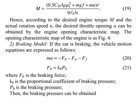
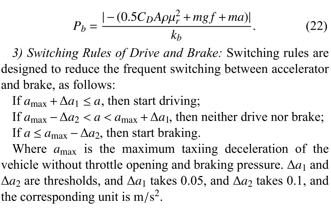
According to statistics, the failure to keep an appropriate safety distance during car following is the main cause of rearend collisions. A safe tracking distance refers to the proper distance between two vehicles that can prevent rear-end collisions without the reducement of the vehicle traffic rate. It is the most effective method to prevent rear-end collisions,and it also affects the control effect of the system. Hence, it is of great significance to establish an appropriate following distance model.
The time headway model is one of the main models to study the safe distance. It can be divided into the constant time headway model and variable time headway model. The latter can change dynamically with the motion state of the vehicle,which is more practical than the former. The traditional variable time headway model, considering the speed of the main vehicle, is expressed as follows [77]:

Fig. 4. Opening characteristic map of the engine.
III. DESIGN AND ANALYSIS OF SAFE DISTANCE
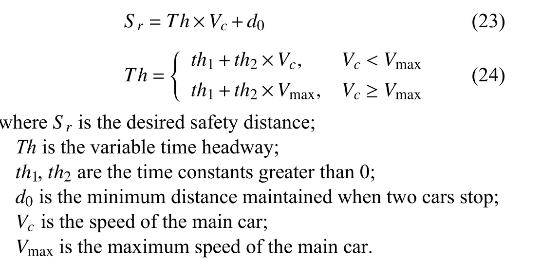
The model is simple and easy to implement, but the motion state of the front vehicle is not considered.
Later, Yanakiev and Kanellakopowlos [78] proposed a new variable time headway model considering the relative speed of two cars, but the variable time headwayThonly changes with the change of relative speed.
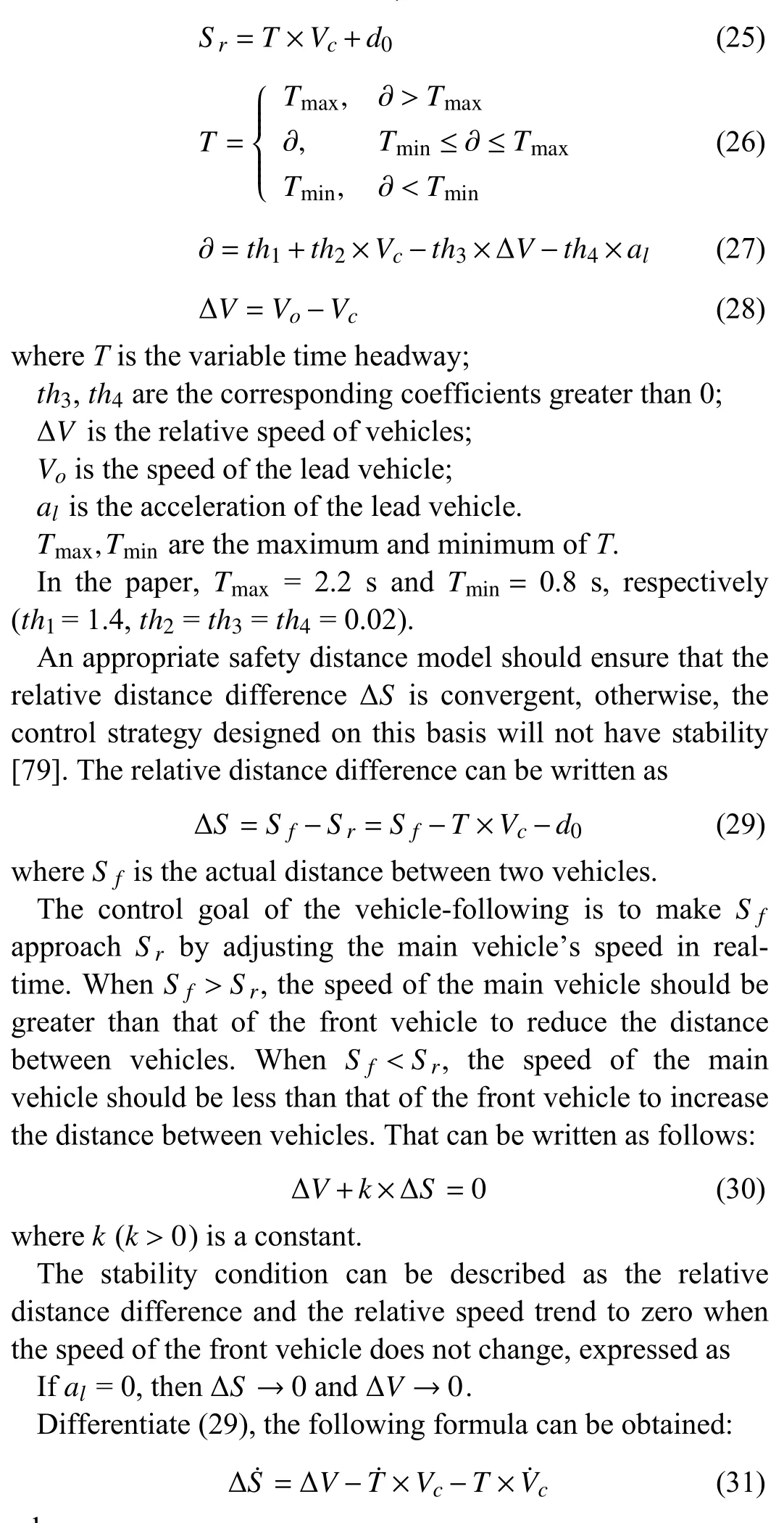
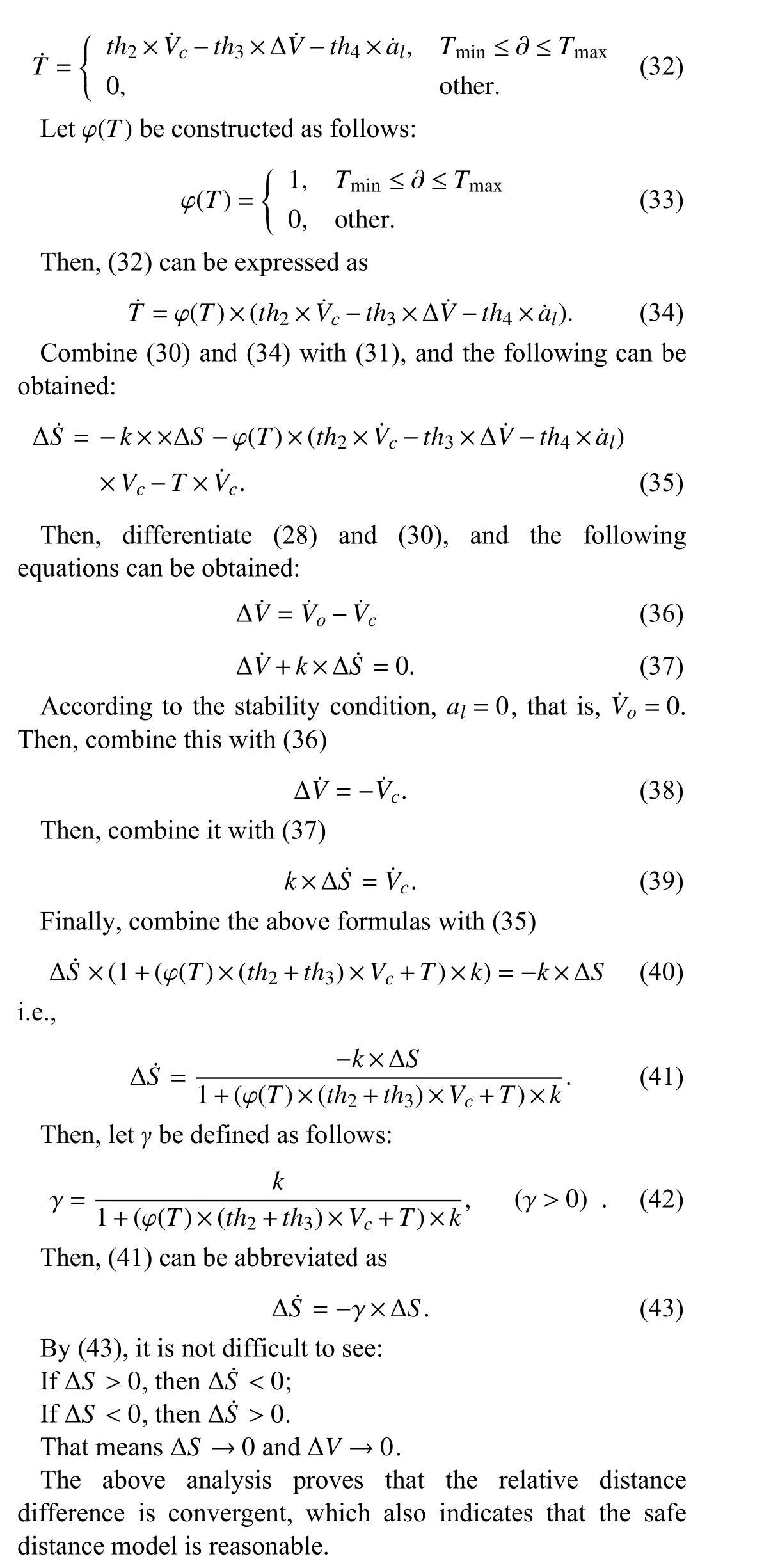
The acceleration represents the changing trend of the vehicle speed, so the distance control strategy considering the acceleration of the front vehicle is helpful to improve the response-ability of the system to the speed change of the front vehicle. Therefore, an improved variable headway model is proposed and used as the safe distance model for vehiclefollowing, which comprehensively considers the speed of the main vehicle, the relative speed of the two vehicles and the acceleration of the front vehicle, written as follows:
where
IV. DESIGN OF HIERARCHICAL CONTROLLER
The hierarchical control structure of the ACFC system designed is as Fig. 5.
In the upper control structure, IT2 FLC is used to calculate the desired acceleration according to the collected information. Then, the lower control structure outputs the desired throttle opening or braking pressure according to the desired acceleration and actual acceleration of the main vehicle, and finally acts on the lower actuator of the main vehicle.

Fig. 5. Control structure of ACFC system.
A. Design of the Upper IT2 FLC
In the paper, the relative distance difference ΔSand the relative speed ΔVare the input variables of the IT2 FLC, and the desired accelerationais the output variable.
1) Fuzzification:Let the universe of ΔSbe [-30, 30] m,where 7 base words are set on the universe, which are described by “negative large”, “negative medium”, “negative small”, “zero”, “positive small”, “positive medium” and “positive large” respectively. These base words can be expressed as ΔS={S1,S2,S3,S4,S5,S6,S7}. The correspondingCoSis shown in Fig. 6.
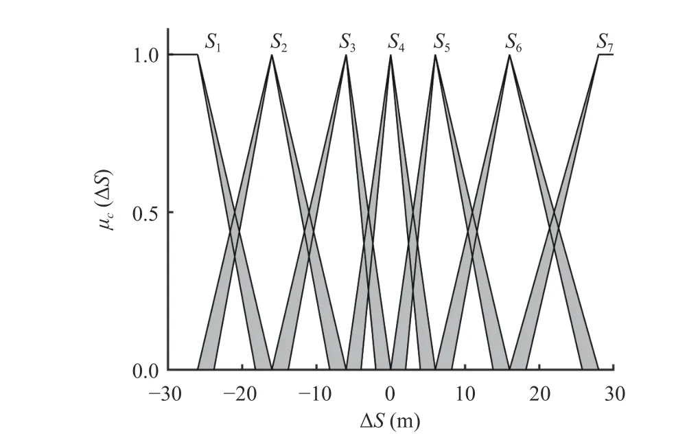
Fig. 6. CoS of the relative distance difference.
Let ΔV= [-10, 10] m/s be divided into 7 base words, which are described as the same as ΔS, expressed asΔV={V1,V2,V3,V4,V5,V6,V7}. The correspondingCoSis shown in Fig. 7.
Leta= [-4, 3] m/s2also be divided into 7 base words,described as the same as ΔS. The base words can be expressed asa={A1,A2,A3,A4,A5,A6,A7}, and the correspondingCoSis shown in Fig. 8.
2) Rule Base:Fuzzy rules are established based on the experience of drivers, and 49 rules are given in Table I.
The Karnik Mendel (KM) algorithm is selected as the typereduction algorithm, and defuzzification is to calculate the center of the results output by the KM algorithm [80].
B. Design of the Lower Controller
In the lower control system, the F+FPIF control is mainly to reduce the interference of the vehicle’s nonlinear factors and external environmental factors and improve the tracking speed and accuracy of the system to desired acceleration.
The mathematical expression of the fuzzy PI controller is as follows:
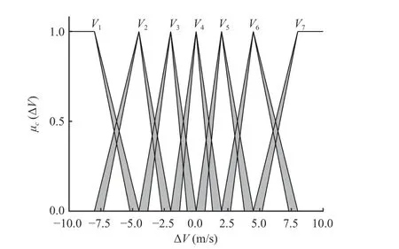
Fig. 7. CoS of the relative speed.
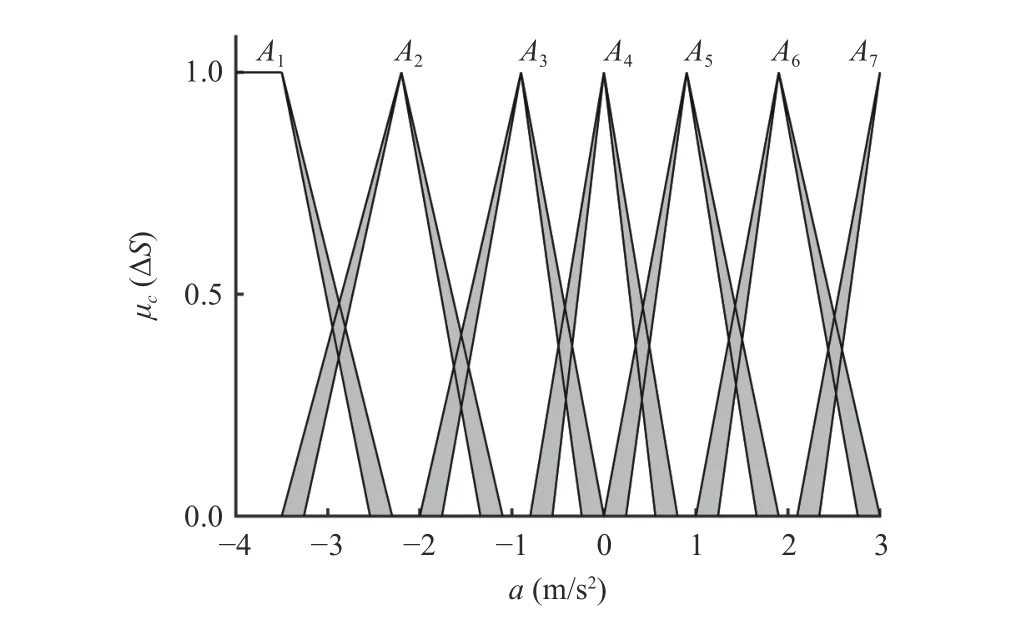
Fig. 8. CoS of the desired acceleration.
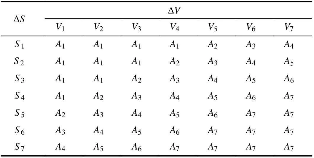
TABLE I FUZZY RULES OF A

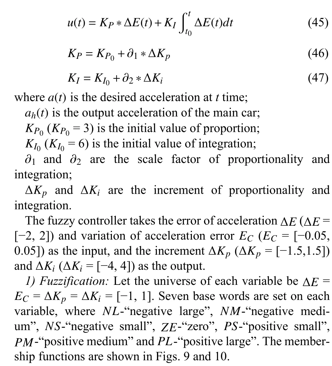
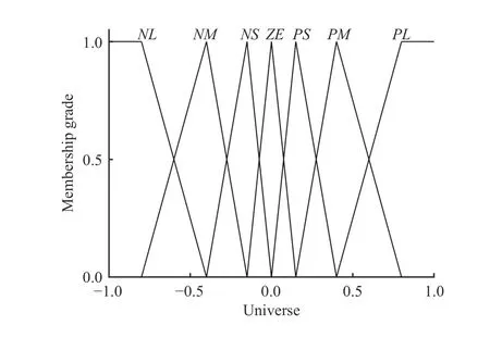
Fig. 9. Membership function diagram of Δ E and E C.
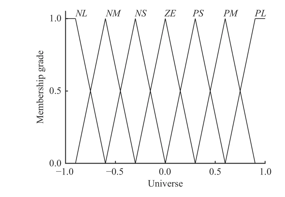
Fig. 10. Membership function diagram of Δ Kp and Δ Ki.
2) Rule Base:According to the expert experience and the simulation results, the control rules are continually modified.Finally, the control rules are shown in Tables II and III.
V. SIMULATION EXPERIMENT
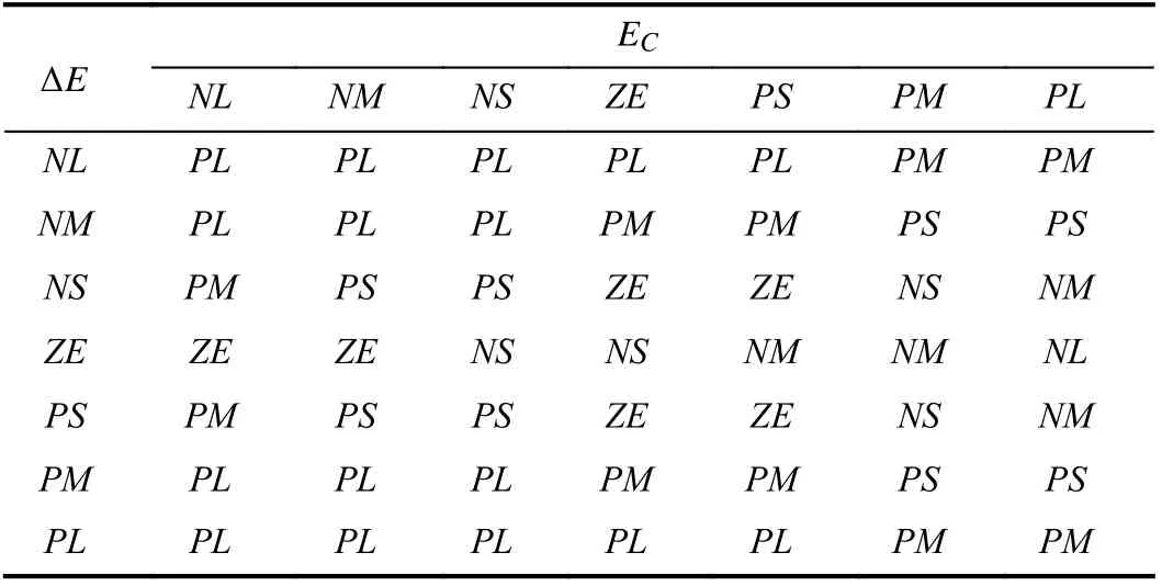
TABLE II FUZZY RULES OF ΔKP
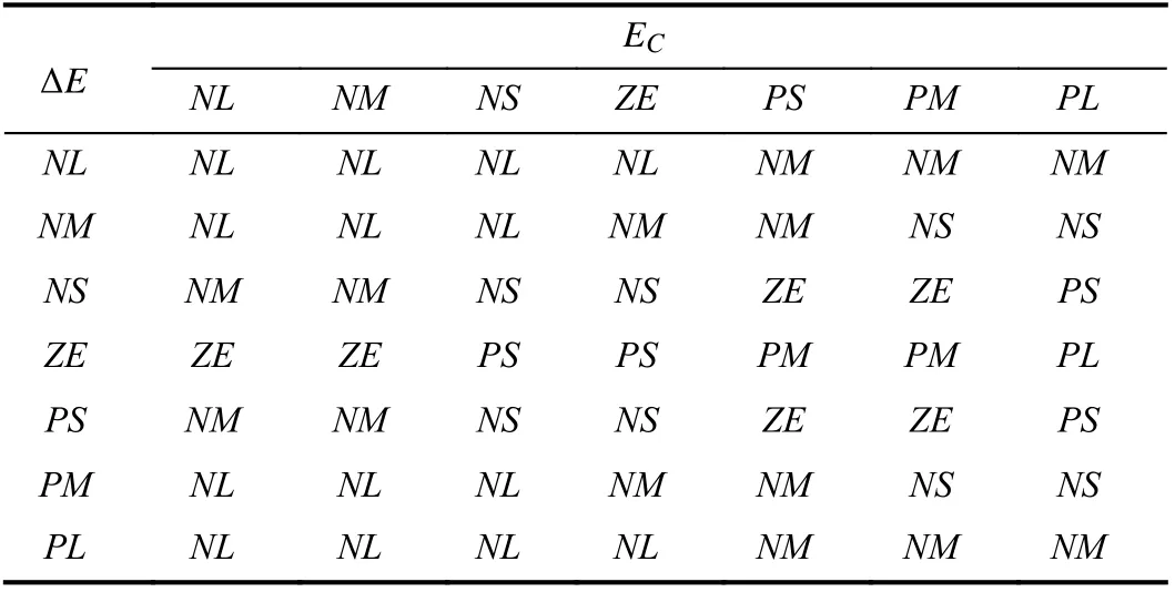
TABLE III FUZZY RULES OF ΔKi
To verify the effectiveness of the lower and upper control methods respectively, working condition 1 and working condition 2 are designed, and simulations are carried out by MATLAB/Simulink and CarSim.
In working condition 1, to verify the validity of the lower F+FPIF control, it is compared with the fuzzy PI control and the traditional method (no lower controller for tracking desired acceleration). Meanwhile, two following scenes with different following speeds are established to study the influence of different speeds on the lower controller.
In working condition 2, the IT2 FLC is respectively compared with PID, LQR, subsection function control (SFC),and type-1 fuzzy logic control (T1 FLC) to verify its effectiveness.
The main parameters of the vehicle model are shown in Table IV.
A. Working Condition 1-Car Cut in Follow
The schematic of the car cut in is as Fig. 11. It assumes that when the main vehicle A is driving normally at the speedVc,another vehicle B with the speedVois suddenly inserted atxmeters ahead. After that, the main vehicle A starts to follow vehicle B.
In order to verify the influence of different following speeds for the lower control methods, the distancexand the speedVoof the inserted vehicle are fixed, and only the speedVcof the main vehicle is changed. The conditions are set as:Vo=60 km/h,x= 40 m.
Experiment 1:Vc= 80 km/h The simulation duration is 20 seconds, and the simulation results under different lowercontrol methods are as follows.The control effect of the lower control method can be evaluated by the performance indexes of speed, distance and acceleration, and acceleration is our main research object. The performance index of the speed and distance is the mean absolute error (MAE, units: m/s and m, respectively). The performance index of acceleration is MAE (unit: m/s2) andte(the time when the value of the acceleration error is first less than 0.1 m/s2, unit: s). The calculation results are shown in Table V.
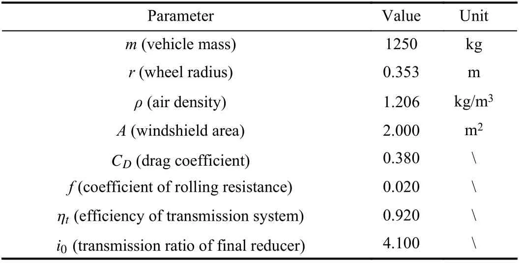
TABLE IVTHE MAIN PARAMETERS OF THE VEHICLE MODEL

Fig. 11. Schematic of car cut in.

TABLE V EVALUATION INDEXES IN EXPERIMENT 1
In Fig. 12(a), on the same experimental platform, the speed of the traditional method has a small overshoot and slight fluctuation at about 9 s, but that of the other two methods have no overshoot and change smoothly. Moreover, based on the evaluation indexes of speed and distance, the F+FPIF control and fuzzy PI control can effectively reduce the MAE compared with the traditional method, and the distance MAE of the F+FPIF control is slightly better than the fuzzy PI control.
Most important of all, the other two methods can significantly improve the tracking accuracy for desired acceleration compared with the traditional method by the acceleration MAE. The acceleration MAE of the F+FPIF control is the smallest and decreases by about 55.56 % compared to the fuzzy PI control. This shows that the F+FPIF control has higher tracking accuracy for desired acceleration than the other two methods.
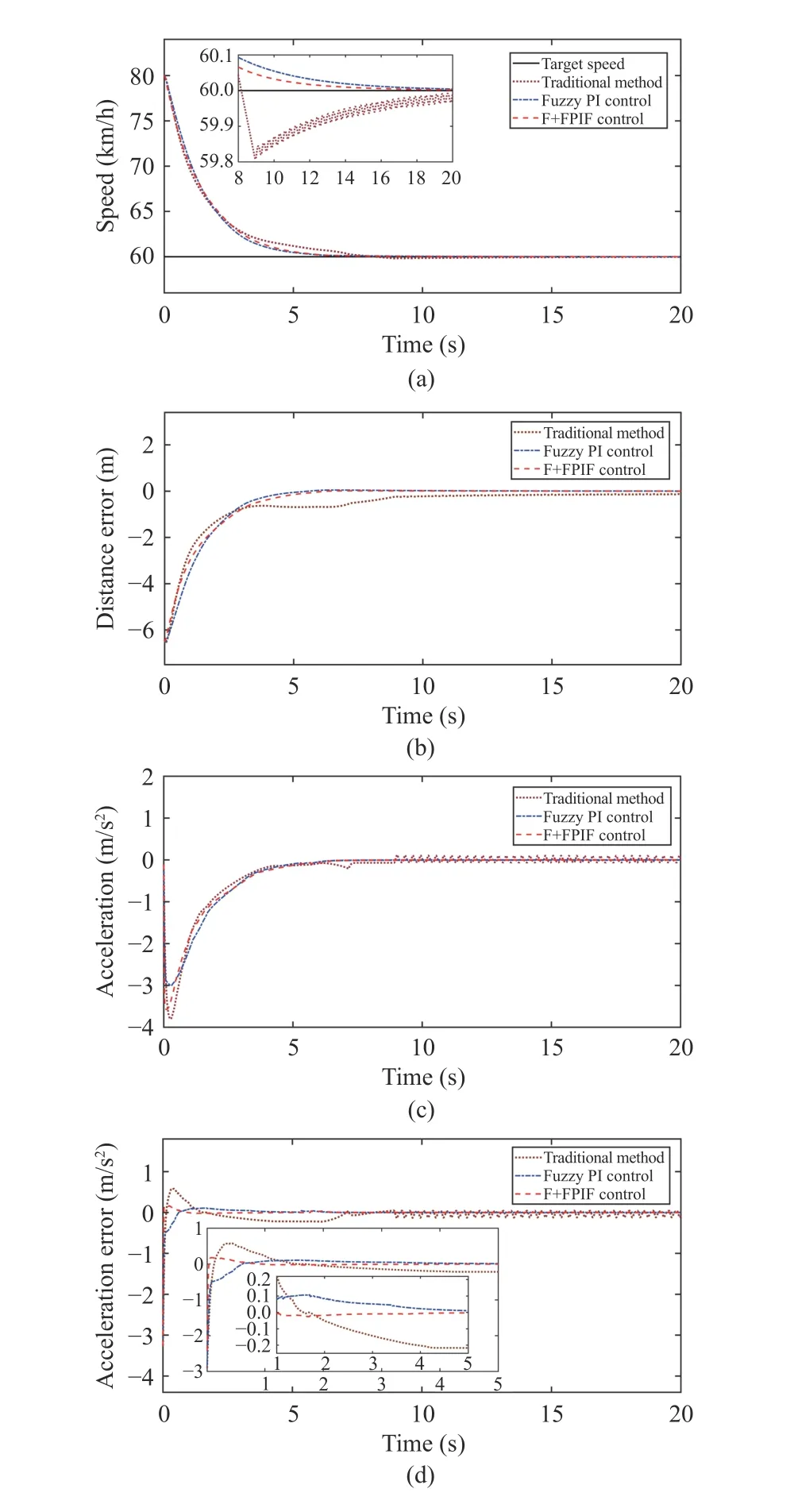
Fig. 12. Results in Experiment 1: (a) Change curves of speed tracking;(b) Change curves of distance error; (c) Change curves of output acceleration;(d) Change curves of acceleration tracking error.
In addition,teof the F+FPIF control is the smallest, which is 0.477 s smaller than the fuzzy PI control. This indicates the F+FPIF control has the fastest tracking speed for desired acceleration. Althoughteof the traditional method is smaller than the fuzzy PI control, the acceleration tracking effect afterteis very poor according to Fig. 12(d).
The above results show that the F+FPIF control can effectively improve the tracking speed and accuracy of the system to desired acceleration.
Experiment 2:Vc= 70 km/h. The simulation results are as follows.
The evaluation indexes are the same as Experiment 1, and the calculation results are shown in Table VI.
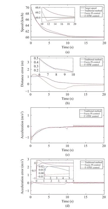
Fig. 13. Results in Experiment 2: (a) Change curves of speed tracking;(b) Change curves of distance error; (c) Change curves of output acceleration;(d) Change curves of acceleration tracking error.
In Fig. 13, it can be seen that the F+FPIF control and fuzzy PI control still have a better control effect than the traditional method. Since the speed of fuzzy PI control decreases slowly during the initial stage, the distance MAE is smaller than the F+FPIF control, which is also related to the safe distance model of the system. This result is as expected, and the other results are similar to Experiment 1.
As for the acceleration indexes, fuzzy PI control can obviously improve the tracking accuracy of the system to desired acceleration compared to the traditional method.However, F+FPIF control has a faster tracking speed and higher tracking accuracy for the desired acceleration than fuzzy PI control. This also shows that F+FPIF control has a better tracking effect for desired acceleration than the other two methods.
Above all, the results under two different tracking speeds show that F+FPIF control can effectively improve the trackingspeed and accuracy of the system to desired acceleration,which also indicates the effectiveness of the control strategy of F+FPIF.

TABLE VI EVALUATION INDEXES IN EXPERIMENT 2
B. Working Condition 2-Car Following Smoothly
The car following smoothly is mainly used to study the control effect of the upper controller. It means that the main car with an initial speedVcclosely follows the lead car, and the initial speed of the lead car isVo, and the initial distance between the two cars isxmeters. The scene schematic is as Fig. 14.

Fig. 14. Schematic of car following.
Since working condition 1 has verified the effectiveness of the F+FPIF control, next the experiments are only done with the F+FPIF control for the lower structure.
At the same time, to verify the impact of different tracking speeds on the upper controller, two following scenarios are provided in the section.
1) The first scenario is that the main car accelerates to follow the lead car at a constant speed, and two experiments with different following speeds are designed to study the influence of different tracking speeds on the upper controller.
2) The second scenario is that the main car follows the lead car with variable acceleration.
Experiment 3:In the first scene,Vc= 50 km/h,Vo= 60 km/h,x= 30 m. The simulation duration is 20 s, and the simulation results under different upper controllers are as follows.
In Fig. 15, the final speed and distance under every controller have a good control effect, which shows the effectiveness of these controllers. However, there are obvious differences in the changes of speed and distance error in the process of following.
The control effect of the controllers is mainly evaluated by the indexes of speed and distance. The speed performance indexes are selected as rising timetr(unit: s), overshootδand MAE (unit: m/s). The performance index of distance is MAE(unit: m). The results are shown in Table VII.
For the speed indexes,trof PID is the shortest, which shows the response speed is the fastest.δof PID and SFC are very obvious, whileδof the other three methods are relatively small, andδof IT2 FLC is the smallest. In addition, the MAE of SFC is the maximum, and the MAE of IT2 FLC is the minimum.
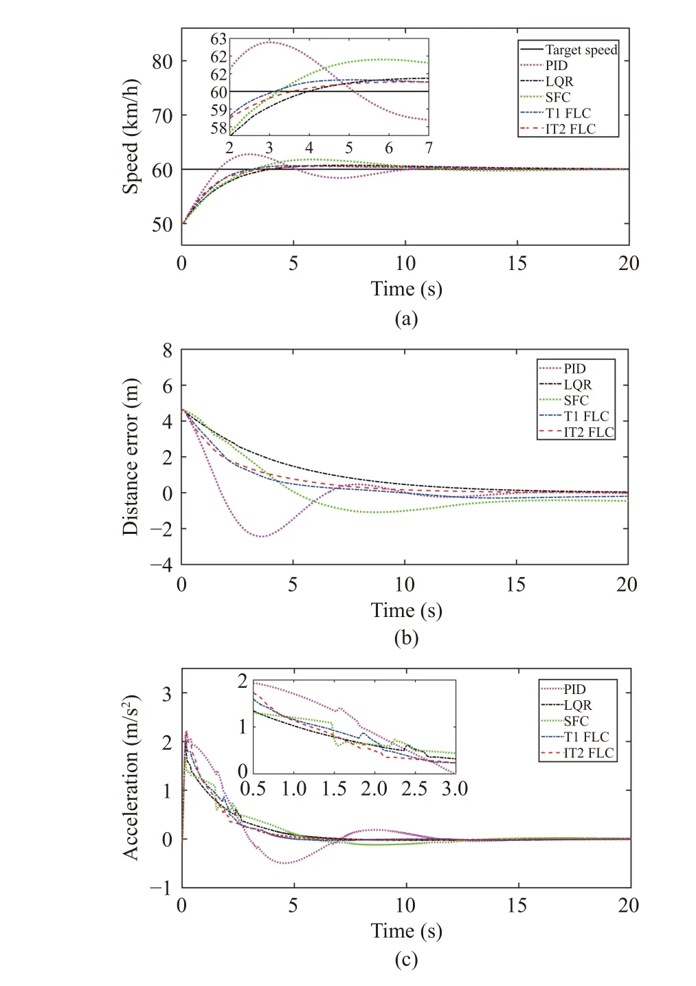
Fig. 15. Results in Experiment 3: (a) Change curves of speed tracking;(b) Change curves of distance error; (c) Change curves of output acceleration.
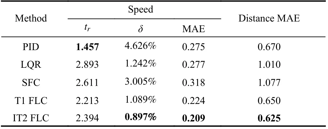
TABLE VII EVALUATION INDEXES IN EXPERIMENT 3
For the distance index, MAE of SFC and LQR are similar and relatively large. MAE of IT2 FLC is the minimum and MAE of PID and T1 FLC are similar to that of IT2 FLC.However, in Fig. 15(b), the distance error of PID fluctuates greatly in the process of following. The larger the fluctuation range of the distance error, the less satisfactory the following effect. Because the positive distance error indicates that the actual distance is greater than the expected safe distance, this will improve the safety of driving, however, it also reduces road utilization. The negative distance error indicates that the actual distance is less than the expected safe distance, which will reduce the safety of driving. By comparison, the changes in distance error of IT2 FLC and T1 FLC are relatively steady,which also shows that they have a good tracking effect on distance. Moreover, the following effect can also be accepted by the driver.
In addition, the change of acceleration of IT2 FLC is smoother than the other four methods by Fig. 15(c).
Thus, on the whole, the above results show that IT2 FLC has a good control effect for speed and distance in the process of following.
Experiment 4:In the first scene,Vc= 50 km/h,Vo= 70 km/h,x= 30 m. The simulation results are as follows.
The performance evaluation indexes are the same as Experiment 3, and the calculation results are shown in Table VIII.
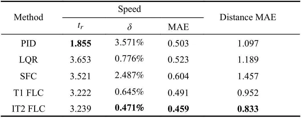
TABLE VIII EVALUATION INDEXES IN EXPERIMENT 4
In Fig. 16, it shows every controller still has a good control effect for the final speed and distance, and only the variations of speed and distance error are different in the process of following.
Table VIII shows the results are similar to Experiment 3.The rising time of PID control is still the smallest, which shows that the response speed is still the fastest, but itsδis also the largest.δof IT2 FLC, T1 FLC and LQR are still small. Moreover, MAE values of speed and distance of IT2 FLC are still the minimum, and the changes in speed and distance error are still relatively stable. That indicates that IT2 FLC still has good control effects.
In summary, IT2 FLC has a good control effect for speed and distance in the process of following the front vehicle at a constant speed.
Experiment 5:In the second scene,Vc= 75 km/h,Vo=82.8 km/h,x= 45 m. Let the lead vehicle move at a variable acceleration. The simulation duration is 60 s, and the simulation results are as follows.
The calculation results of each index are shown in Table IX,where the unit of peak value is km/h.
In Fig. 17(a), the speed of the main vehicle under each controller changes closely with the change of speed of the lead vehicle, and the final speed error tends to zero, which demonstrates the effectiveness of these controllers. However,differentially from the previous two experiments, the control effects of these controllers have changed accordingly.
For the speed index, the peak values of each controller are similar except for SFC. MAE of SFC is still the largest, but MAE of PID and LQR are relatively small. MAE of IT2 FLC is slightly higher than that of PID, LQR and T1 FLC.
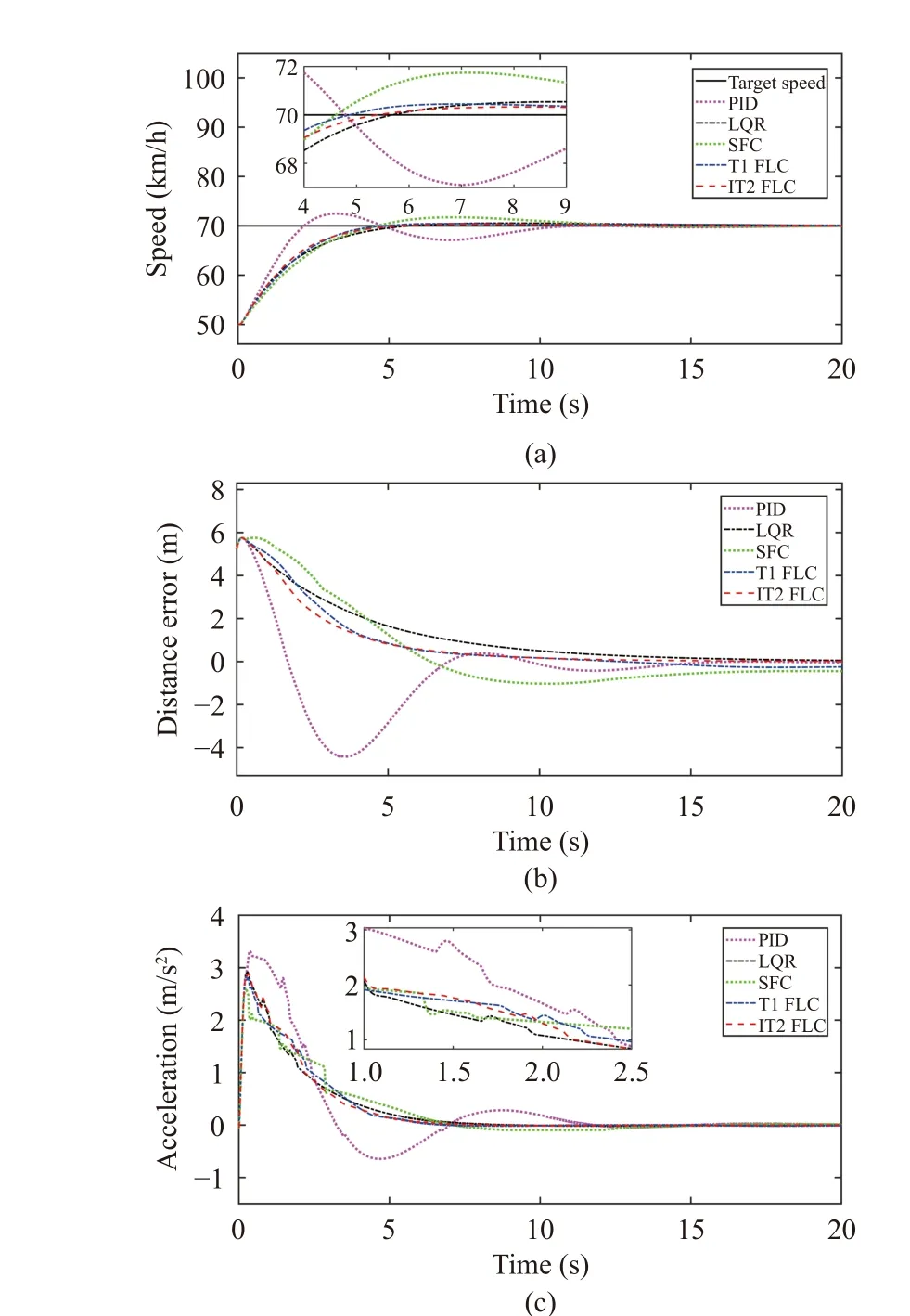
Fig. 16. Results in Experiment 4: (a) Change curves of speed tracking;(b) Change curves of distance error; (c) Change curves of output acceleration.
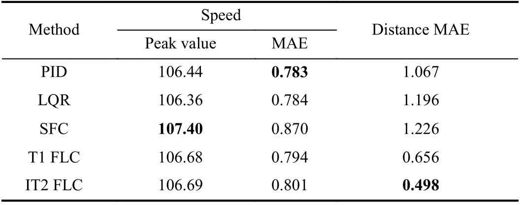
TABLE IX EVALUATION INDEXES IN EXPERIMENT 5
However, the distance MAE of IT2 FLC is still the smallest.Compared with PID, LQR, SFC and T1 FLC, MAE of IT2 FLC decreases by 53.33%, 58.36%, 59.38% and 24.09%,respectively. Furthermore, in Fig. 17(b), IT2 FLC has a smaller fluctuation in distance error compared to the other four methods in the process of following, and the meaning of fluctuation of the distance error has been described in Experiment 3, which illustrates that the control effect of IT2 FLC is superior to the other four methods on distance.
In summary, the above three experimental results show that IT2 FLC has a good control effect for speed and distance in the process of following, which also demonstrates its rationality and effectiveness.
VI. CONCLUSION
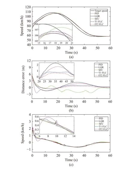
Fig. 17. Results in Experiment 5: (a) Change curves of speed tracking;(b) Change curves of distance error; (c) Change curves of output acceleration.
In this paper, a comprehensive control strategy is proposed for the hierarchical ACFC system, which integrates the variable time headway model, type-2 fuzzy control, F+FPIF control and inverse longitudinal dynamics model of vehicles.In the upper control structure, an IT2 FLC is designed to simulate the driver’s operating habits. Meanwhile, the control strategy of F+FPIF is given for the lower control structure to improve the tracking speed and accuracy of the system to desired acceleration. In addition, an improved variable time headway model is analyzed and used as the safe distance model for vehicle-following, and the inverse longitudinal dynamics model of vehicles is also established. Finally, to verify the validity of the control strategy, the corresponding model is built and simulated by MATLAB/Simulink and CarSim. The simulation results show the rationality and effectiveness of the control strategy, where F+FPIF control of the lower structure can effectively improve the tracking accuracy and speed of the system to desired acceleration, and IT2 FLC of the upper structure also has a good control effect on the speed and distance in the process of following. Hence,these methods provide a new way of thinking in the research of vehicle-following control.
Cooperative adaptive cruise control (CACC), which can improve driving safety and alleviate traffic jams, has become one of the significant technologies for highway safety construction [81]-[85]. It can make vehicles in the fleet drive at coordinated speed and keep a small distance between vehicles.However, the control method needs continuous adaptive learning and optimization to cope with various external disturbances and changes. In recent years, deep learning has become one of the research hotspots in the field of artificial intelligence, and it is widely used because of its strong selflearning ability [86]-[90]. Nowadays, according to the respective advantages of fuzzy theory and deep learning, some researchers have proposed combining them to deal with various problems in the engineering field, and achieved excellent control effects [91]-[95]. Therefore, the next work arrangement is to combine deep learning with IT2 FLS to study CACC.
 IEEE/CAA Journal of Automatica Sinica2022年9期
- IEEE/CAA Journal of Automatica Sinica的其它文章
- Autonomous Maneuver Decisions via Transfer Learning Pigeon-Inspired Optimization for UCAVs in Dogfight Engagements
- Efficient Exploration for Multi-Agent Reinforcement Learning via Transferable Successor Features
- Reinforcement Learning Behavioral Control for Nonlinear Autonomous System
- An Extended Convex Combination Approach for Quadratic L 2 Performance Analysis of Switched Uncertain Linear Systems
- Adaptive Attitude Control for a Coaxial Tilt-Rotor UAV via Immersion and Invariance Methodology
- Comparison of Three Data-Driven Networked Predictive Control Methods for a Class of Nonlinear Systems
