Fundamental study towards a better understanding of low pressure radio-frequency plasmas for industrial applications
Yong-Xin Liu(刘永新), Quan-Zhi Zhang(张权治), Kai Zhao(赵凯), Yu-Ru Zhang(张钰如), Fei Gao(高飞),Yuan-Hong Song(宋远红), and You-Nian Wang(王友年)
Key Laboratory of Materials Modification by Laser,Ion,and Electron Beams(Ministry of Education),School of Physics,Dalian University of Technology,Dalian 116024,China
Keywords: RF plasma,electron heating,discharge mode,pulse modulation,electromagnetic effects
1. Introduction
Radio-frequency(RF)plasmas have found wide applications in hi-tech industries. Especially in semiconductor industries,RF plasma sources have become indispensable core part of semiconductor devices,which are used for material etching and thin film deposition.[1–3]Two typical RF plasma sources commonly used in semiconductor industry are the capacitively coupled plasmas (CCP) reactor and the inductively coupled plasmas (ICP) reactor, see Fig. 1. In the 1970s, people developed the CCP reactor, which contains two parallel-plated electrodes, spaced by a few centimeters, in a vacuum chamber. One electrode is driven by an RF power source of typical power in the range 100 W–1000 W and of the frequency in the range 13.56 MHz–200 MHz. The plasma density in CCP is relatively low, i.e., in the range of 1015m−3–1016m−3.The ICP reactor is driven by an RF power supply via a planar coil(or antenna)sitting on a dielectric window on the top of a vacuum chamber, or via a helical coil surrounding a dielectric cylinder. The RF current flowing in the coil induces electromagnetic fields that can transfer energy into electrons inside the chamber. The plasma density of an ICP is determined by the magnitude of the RF current. As the power efficiency of inductively coupling is significantly higher than that of capacitively coupling, the typical density in the ICP is 1–2 orders of magnitudes higher than that in the CCP. In practical applications,e.g.,etching process,two separated RF power sources are simultaneously used to drive the CCP and the ICP reactors. In dual-frequency driven CCPs, the highfrequency source can control the plasma density, while the low-frequency source determines the distribution of ion energy bombarding the electrode, where a wafer is placed.[4,5]In an ICP system, besides the source coil used to generate a plasma,the second RF source is usually used to bias the substrate holder,and thereby,to control the ion energy.[6,7]In microelectronic manufacturing,the CCP source is primarily used to etch dielectric,e.g.,silicon dioxide,while the ICP source is routinely employed to etch metal and silicon. An in-depth understanding of the fundamental processes occurring in the RF plasmas is of extreme importance to improve the performance of plasma sources used in these practical applications, which could ultimately create enormous societal benefits.
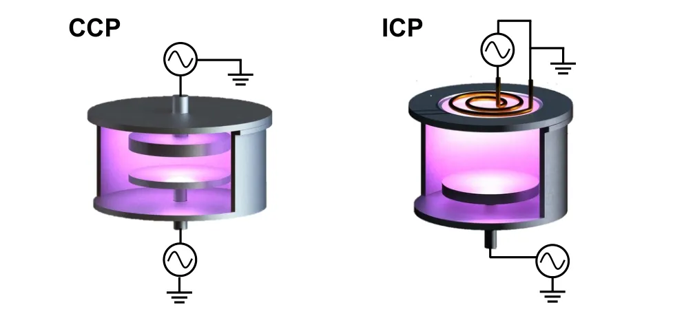
Fig.1. The schematic of typical CCP and planar-coil type ICP reactors.
The optimization of technological processes requires a fundamental knowledge of the charged particle dynamics in the RF discharges. The electron heating or electron power absorption mode in time-varying fields is one of the fundamental issues for the sustainment of RF discharges, as these basic processes determine the electron energy distribution function(EEDF),of which the electrons with energies higher than thresholds are responsible for the gas-phase chemical reactions,e.g.,ionization,excitation,dissociative attachment processes, etc.[8,9]In Section 2, we discuss the electron heating mechanism in CCPs and ICPs. These microscopic processes significantly influence the concentrations and spatial distributions of charged species and neutral radicals. On the other hand,the acceleration and collisionality of various ionic species when traversing the sheath region define their energy distribution functions at the substrates, which play a key role in the interaction of the plasma with material surfaces, e.g.,atomic layer etching.[10]In Fig. 2, we present a schematic of the interactions of various particles (electron, ions, photon, and neutrals) with the boundaries (the RF electrode and the sidewall) of a plasma chamber. It can be seen that the secondary electron emission can be induced by ion and atom bombarding the surface and photon irradiation. Besides, part of the outward moving electrons are reflected back to the bulk region when arriving at the boundaries. Some interactions,e.g., ion sputtering and surface chemical reactions, play very crucial role in material processing.
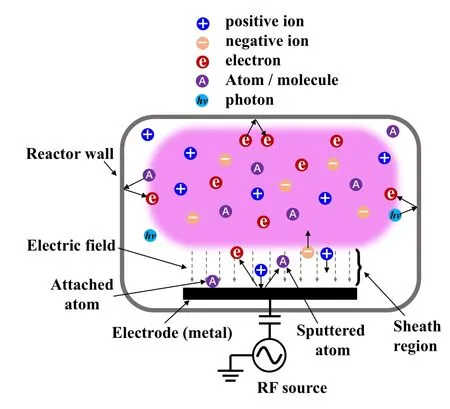
Fig. 2. Schematic of charged particles–surface interactions in a plasma chamber.
Compared to the low-energy electrons,high-energy ones are capable of ionizing and exciting background atoms or molecules,thus playing a more important role in determining the macroscopic properties of an RF discharge. Plasma operation mode(or discharge mode), represented by the spatiotemporal distributions of excitation/ionization rate caused by highly energetic electrons, have been a hot topic, which has been extensively studied both in experiment and via simulations recently.[11–13]The highly energetic electrons are responsible for generation and sustainment of a plasma, so understanding the discharge mode is also key for the optimization of some important plasma parameters and improvement of the quality of the independent control of the ion flux and energy on the substrate. In this review,some typical discharge modes,the mode transitions,their effects on the macroscopic parameters of RF discharges,and especially the underlying physics,are described in Section 3.
In the semiconductor manufacturing, the feature size of a transistor is shrinking approaching the atomic size, some plasma-induced problems will appear in continuous-wave(CW)driven RF plasmas,such as the continuous ion bombardment and sputtering,[14,15]the highly intense photon radiation of vacuum ultraviolet,[16–18]the surface charging,etc. To address these formidable challenges, a variety of methods have been put forward to optimize plasma properties. One of the most promising candidates is to pulse modulate the RF power source. Numerous fundamental studies and practical processing have proved that pulse modulated plasmas can produce a higher etching rate, better uniformity, and less structural,electrical or radiation (e.g., vacuum ultraviolet) damage. Besides,pulse modulated plasmas can also ameliorate unwanted artefacts in etched micro-features such as notching, bowing,micro-trenching and aspect ratio-dependent etching.[19]As such,pulse modulated plasmas have become indispensable in the etching process of the next generation of micro-devices with a feature size in the sub-10 nm regime. The research of pulse modulated RF plasmas is introduced in Section 4.
Currently,a 300 mm-diameter wafer(the substrate or the electrode can be a bit larger) in a CCP reactor is commonly used in the semiconductor industries,and the evolution of the wafer to a larger size, i.e., 450 mm, is in the plan, aiming to increase productivity and to decrease cost. In etching process by a CCP reactor,a very-high-frequency(VHF)power source is commonly used to produce a high-density plasma.The driving frequency(60 MHz is widely used nowadays)is expected to be higher, e.g., higher than 100 MHz, in the next generation of CCP sources. This higher frequency not only produces a high plasma density,and therefore a high etching rate,but also gives rise to a reduced ion bombarding energy,which is being required to process integrated circuits with smaller critical dimensions (gate widths). In all, increasing both the substrate size and the excitation frequency in large-area CCP reactors becomes a trend for current plasma processing. However, if the excitation wavelength in a plasma becomes comparable to the electrode dimension and the plasma skin depth becomes comparable to the electrode spacing, so-called electromagnetic(EM)effects,such as the standing wave effect and the skin effect,can become the most important limitations for processing uniformity.[20,21]In Section 5,an overview is given on the theoretical, numerical and experimental investigations that have recently been carried out to understand these EM effects. Besides,some methods of improving the plasma uniformity are also summarized.
This review is organized in the following way. In Sections 2–5, the research progress of some typical topics in RF plasma field, including electron heating, discharge mode,pulse modulated plasma, and electromagnetic effects, are respectively described in details. Finally, the conclusions and outlook are given in Section 6.
2. Electron heating
To sustain an RF discharge, electrons need to continuously gain energy from RF electric field to ionize/excite background gas.Therefore,electron heating mechanisms,i.e.,how electrons gain energy from the electric field, have long been hot issues in the research field of RF discharges.There are two main electron heating mechanisms that are considered to be dominant in RF discharges:(i)Ohmic heating due to electron–neutral collisions, and (ii) stochastic heating due to momentum transfer from the interaction between electrons and the RF oscillating sheaths. It is usual to introduce the macroscopic electron current densityJe=−eneuto understand the Ohmic heating, whereeis the elementary charge,neis the electron number density anduis the mean electron velocity.The Ohmic power transfer per unit volume can be then expressed as

whereσm=e2ne/meυmis direct current conductivity,meis the electron mass,υmdenotes the electron momentum transfer collision frequency and the brackets〈〉Tdenote a time average of a physical quantity over one RF periodT.[22]The fundamental mechanism that transfers the RF power to electrons’thermal energy is the breaking of the phase-coherent motion of individual electrons by collisions,leading to Ohmic heating of electrons. According to Eq.(1),Pohmis proportional toυm,so Ohmic heating dominates an RF discharge at relatively high pressures.
The phase-coherence can be broken, i.e., the phase randomization can also occur, due to electron thermal motion in spatially inhomogeneous RF electric fields, even in the absence of collisions,leading to collisionless heating. This collisionless heating is named as stochastic heating, which can dominate at low pressures. As the electron thermal velocity is much higher than the ion thermal velocity,a positively charged sheath region,which features a high electric field,forms at the plasma boundary adjacent to the electrode. The presence of the sheath region leads to a large spatial gradient of the electric field from the plasma bulk to the electrode surface. When the electrode is powered by an RF voltage, the sheath (or strong electric field)region expands and collapses during one RF cycle, inducing the stochastic heating. Generally, electrons are heated,without collision,by repeated interaction with RF oscillating electric fields that are localized within a sheath region adjacent to electrodes in a CCP or skin layer in an ICP operated at low pressure.[8]The schematic of electron–field interaction shown in Fig.3 can be simplistically described by a well-known “hard wall” model. In this model, the plasma sheath edge is regarded as a moving rigid barrier that specularly reflects all incident electrons.[8,9]As can be revealed,an incident electron is either accelerated by interacting with the expanding sheath (see the scenario A in Fig. 3) or decelerated by interacting with the collapsing sheath (see the scenario B in Fig. 3). The velocity of the reflected electron,vr,is given byvr=−vin+2ush, wherevinis the velocity of the incident electron andushis the velocity of the moving sheath edge. Since head-on collisions are more frequent than overtaking collisions due to larger relative velocity in the head-on collision case, the consequence is that the electrons can gain net energy from the interactions on the time average.
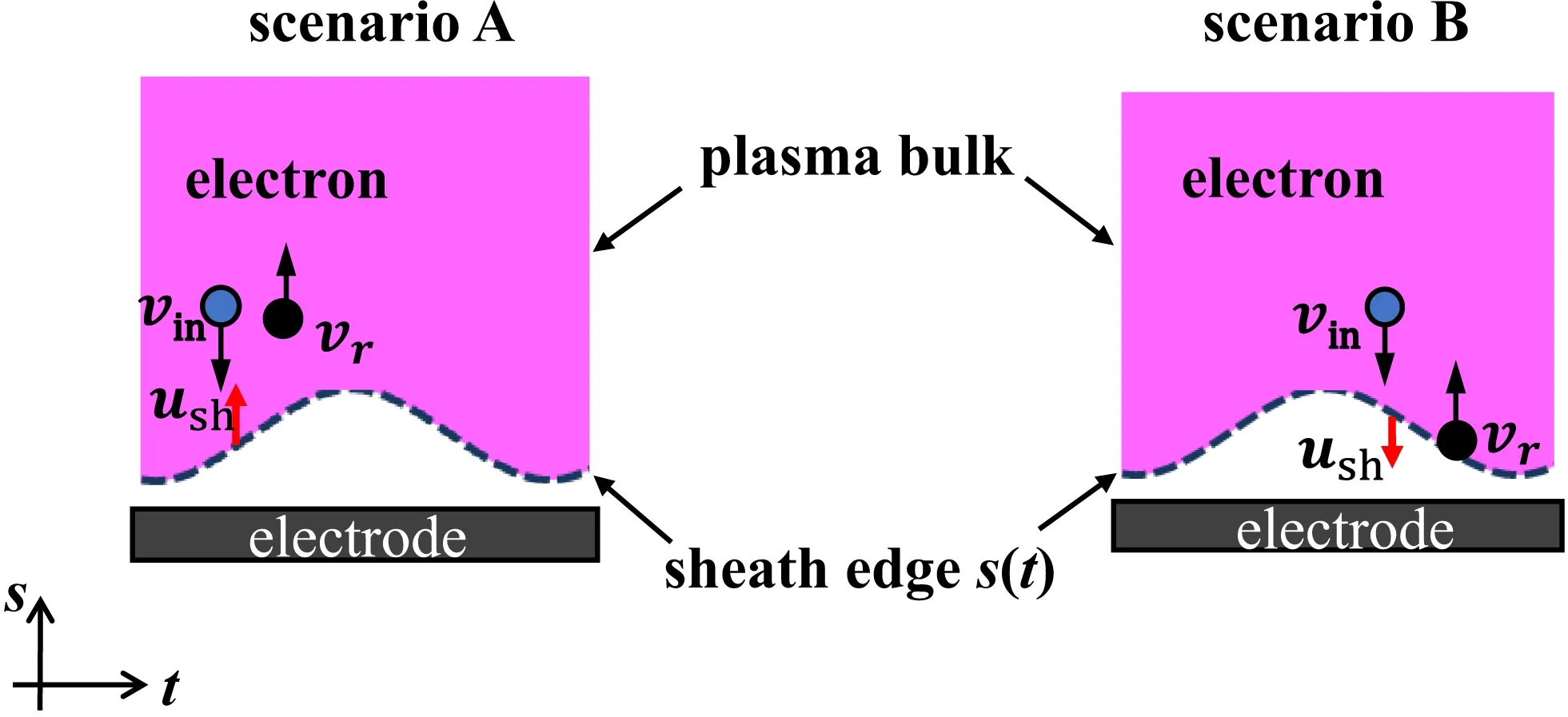
Fig.3. A sketch of interactions between an incident electron and the RF oscillating sheath edge. Scenario A:head-on collision, and scenario B:overtaking collision. Note that the red arrow indicates the moving direction of the sheath edge.

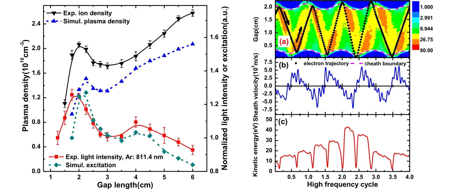
Fig.4. Left panel: plasma density and light intensity versus electrode gap length. Solid lines are from experimental measurements,while dashed lines are from PIC/MCC simulations. Right panel: (a)spatial–temporal evolution of ionization rates(contours)from the simulations,together with sheath edges(dashed lines)and the trajectory(dots)of a typical bouncing electron. (b)The corresponding expanding speed of the powered sheath,and(c)the evolution of the kinetic energy for the corresponding electron. Reprinted with permission from Ref.[23].
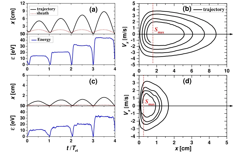
Fig. 5. Position of a typical bouncing electron and of the sheath edge,and the electron kinetic energy as a function of time at(a)13.56 MHz and(c)60 MHz. Temporal evolution of the resonance in the electron x–vx (unit in 106 m/s) phase space at (b) 13.56 MHz and (d) 60 MHz. Smax is the maximum sheath width. Reprinted with permission from Ref.[24].
However, it is worth noting that although the electrons can acquire high energy from the oscillating sheath,the power cannot be effectively deposited if the energetic electrons do not experience any collision with background atoms or molecules,but directly lose on the electrodes when their energy is high enough to overcome the sheath potential. Therefore, Ohmic heating also plays an important role in the overall electron power absorption. In other words,the stochastic heating produces anisotropic electron beams, while the effective heating only occurs when the anisotropic distribution of the velocity components is redistributed in an isotropic manner by collisions with the neutral particles. The combination of electron power absorption in an electric field and the isotropization due to collisions contributes to the overall electron heating.[9]
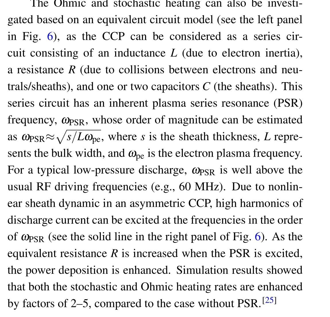
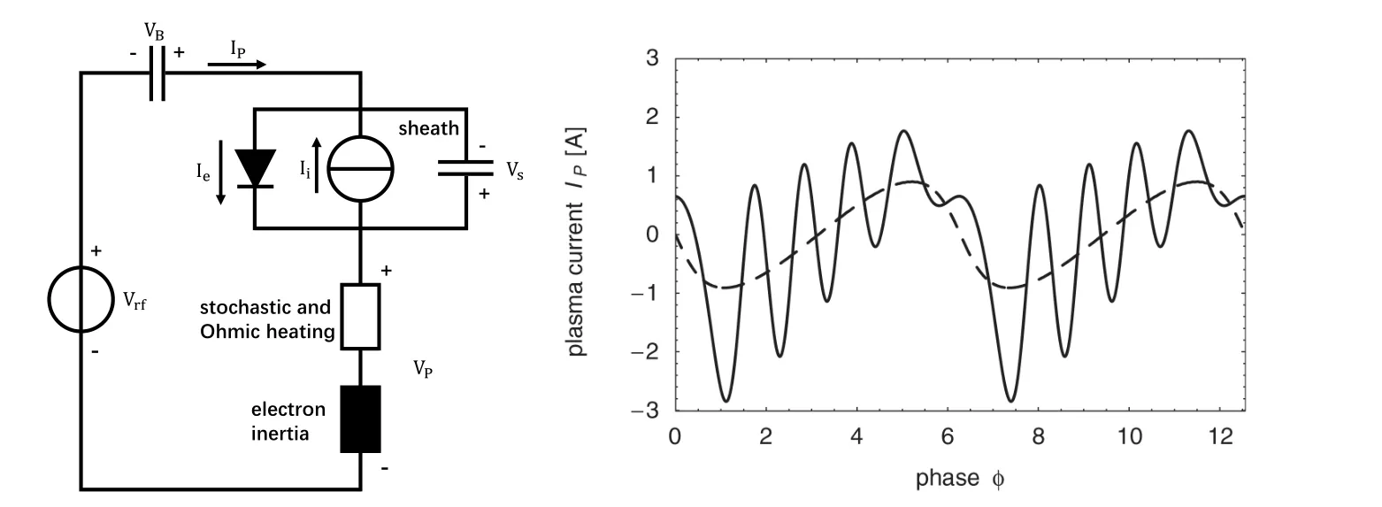
Fig. 6. A sketch of the equivalent series circuit in an asymmetric capacitive discharge (left), and plasma current IP for both high frequency harmonics(solid line)and the fundamental frequency current(dashed lines)where PSR effects do not occur(right). Reprinted with permission from Ref.[25].
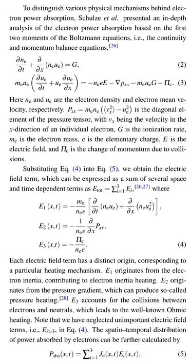
whereJe=qneueis the electron current density,andEiis the electric field, which is defined by Eq.(4). This approach allows to explicitly identify the physical origins of electric field generation and the corresponding electron power absorption with high spatial and temporal resolution within one RF period. By an combination of Boltzmann moments analysis and PIC/MCC simulations,Vasset al.quantified the power deposition rates caused by the collisionless (electron inertial and pressure) heating and collisional (Ohmic) heating.[27]They pointed out that by decreasing the gas pressure, the Ohmic heating is suppressed,while the pressure heating is enhanced.Different from previous understanding,[8]the Ohmic heating predicted by this method still contributes significantly even at very low pressures. At the lower limit of the gas pressure of interest,Ohmic heating rate can be comparable to the pressure heating, and the electron inertial heating component can be negligible. Figure 7 shows an example of the spatiotemporal plots of the power density within one RF cycle in a CCP(see Ref.[9]for more details).
Different from that in CCP where the axial electric field(perpendicular to the electrode surface) dominates the electron heating,there,however,exists another electric field component in ICP, which is able to heat electrons, causing the stochastic(collisionless)heating.[29]Figure 8 shows a dielectric cylinder with a radius ofaand a height ofh(h≫a),and the plasma is sustained inside the tube by a solenoidal coil,which is wound around the cylindrical chamber. The alternating RF current in the coil generates a time varying magnetic field,B,along thez-axis direction inside the tube, thus inducing the azimuthal electric field,Eϕ. The electrons then gain energy from the electric field to partially ionize the background gas,sustaining the discharge.
The spatio–temporal distribution of the electromagnetic field inside the chamber can be described by the Maxwell’s equations

whereµ0is the vacuum permeability,Jeis the electron current density, andJextis the current density in the coil. Note that the displacement current is neglected.
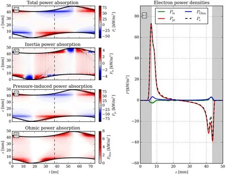
Fig. 7. (a) Total electron power density, Pabs; (b) electron power absorption due to inertia effects, Pin =JeE1; (c) electron power absorption due to pressure heating, Ppre =JeE2; and(d)electron power absorption due to collision, POhm =JeE3. The left panels present spatiotemporal results,the solid black lines indicate the positions of the sheath edges,and the vertical dashed line represents the time at which the temporal snapshot on the right side is shown. x=0 and 50 mm indicate the powered and grounded electrodes,respectively. The gray areas on the right side indicate the sheaths. Discharge conditions: argon gas,3 Pa,500 V,13.56 MHz. Reprinted with permission from Ref.[9].
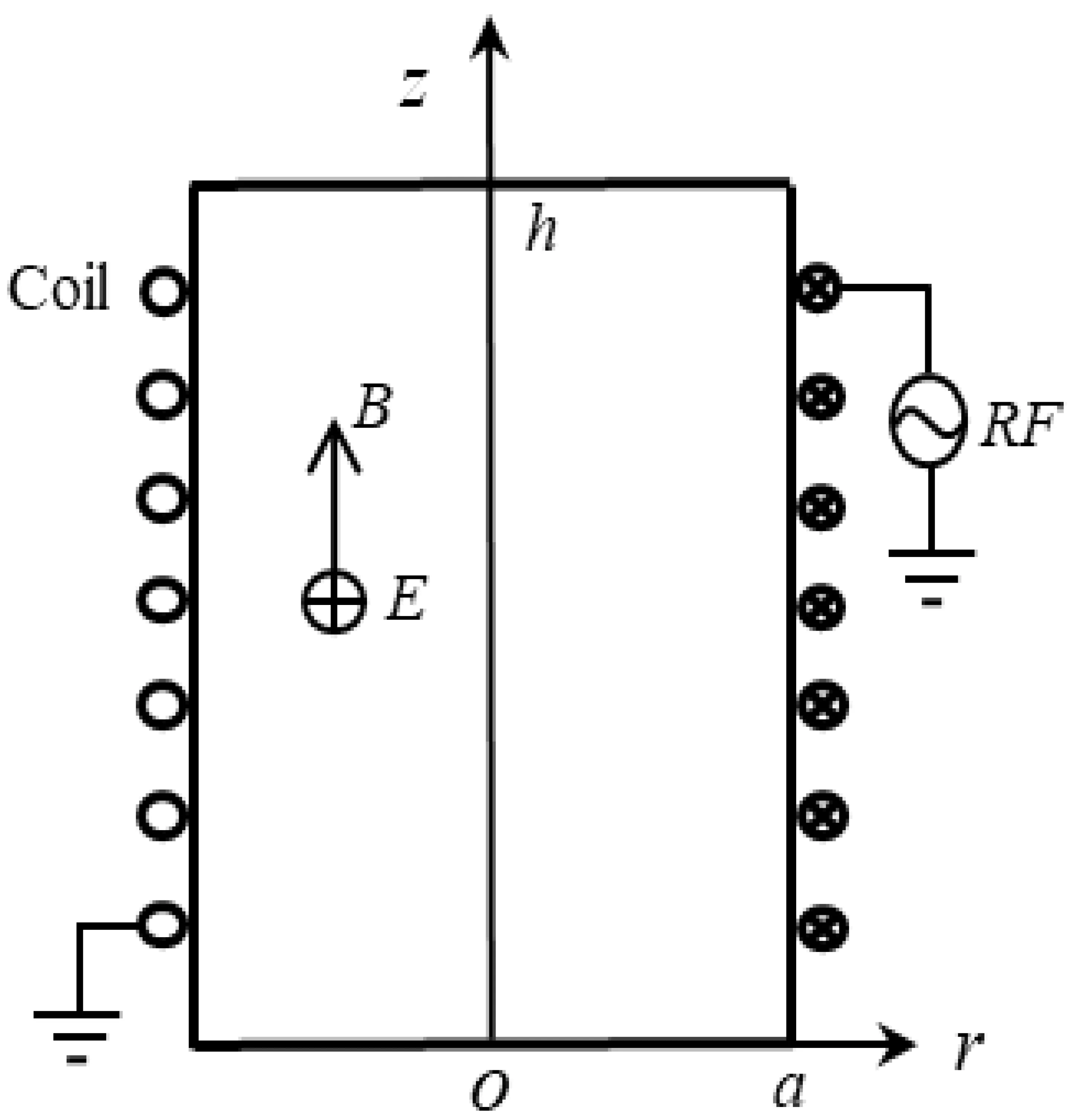
Fig.8. A sketch of an ICP reactor with a cylindrical coil.
As the magnetic field, the electric field and the electron current density in the ICP have time-dependent harmonic oscillating form,we have
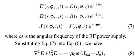
wherek0is the wave number of electromagnetic waves. All physical quantities are assumed to be axisymmetric,and therefore, the electromagnetic fields have only the following components:E ≡{0,Eϕ,0};B ≡{Br,0,Bz},whereBrandBzare the radial and the axial component of the magnetic field,respectively. The capacitive field is assumed to be Faraday shielded,the azimuthal field component,Eϕ,can be thus calculated in the(r, z)cylindrical coordinate system by differentiating Eq.(8)

AsEϕdominates the electron heating in ICP, the electron heating rate can be determined whenEϕis obtained by solving Eq.(9).
In the low-pressure regime, the Ohm’s law,Je=σEϕ(σis conductivity), does not hold between electron current and electric field,due to the smaller electron–neutral collision frequency than the RF frequency (i.e., electron dynamics is non-local).[30]In this case,the electron current density,Je,relies on the profile of the electric field on the spatial scale of the order of the mean free path,[31]which is due to the spatial dispersion of conductivity caused by electron thermal motion.A non-local conductivity depending on the spatial position is therefore required to determine the electric field penetration into the plasma. By solving the Maxwell’s equations and the linearized electron Boltzmann’s equation, You and Yoon[32]derived the non-local conductivity in the solenoidal ICP, and predicted the anomalous skin effect as well as negative power absorption. These theoretical predictions have been observed in the experiments of the planar[33]and the solenoidal[34]ICPs operated at low pressure. Recently, Yanget al.studied the effects of the conductivity during the transition from collisionless to collisional regimes in cylindrical ICPs by a numerical model, which is based on self-consistent coupling of the electron kinetics equation,electromagnetics equation,and global model equations.[35,36]For simplification, they solved the electromagnetics equations in a rectangular (x,z) coordinate system. The local and non-local conductivities for arbitrary electron energy distribution are respectively given as[35]
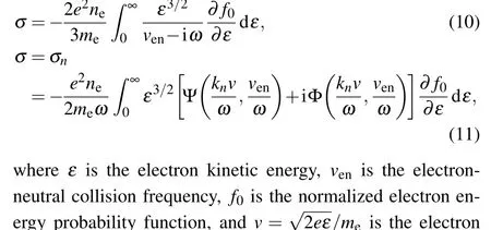

In Ref.[35],the non-local relation between electron current and electric field as well as the existence of negative power absorption was verified in the non-local conductivity case at low pressures(collisionless regime),as shown in Fig.9.However, the phenomena above were not captured under the local conductivity case. As the pressure increases, the electron current and electric field comply with the conventional Ohm’s law and the negative power absorption vanishes for both non-local and local conductivity cases. This suggests that the discharge experiences a transition from collisionless to collisional regime as the pressure increases. The local conductivity is only valid for the relatively high pressures where the collisional heating dominates,while the non-local conductivity is valid no matter what heating mechanism dominates.Therefore, the consideration of the non-local conductivity in a numerical model is very important to capture the important physical properties in low pressure regime.
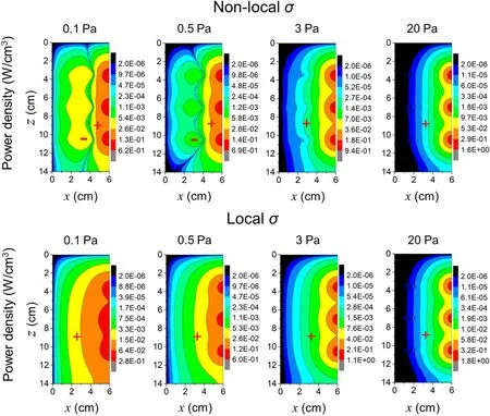
Fig.9. The 2D profiles of absorption power density at different pressures with non-local and local conductivity σ.[35]
3. Discharge modes
In low pressure RF plasmas, electrons, which are generally confined within the bulk region for most of time within one RF period, can obtain energy via interacting with the RF electric field. By contrast, ions in the bulk cannot response to the RF electric field instantly due to their large mass, but the ions at the sheath edge are accelerated by the sheath electric field towards the electrode, and play an important role in material processing. How do the electrons gain and lose their energy in the RF electric field, i.e., electron heating mechanism,determines the EEDF,as well as the proportion of highenergy electrons. These highly energetic electrons can ionize and excite background molecules, and consequently, are responsible for the sustainment of a plasma. So,how the plasma is sustained by these highly energetic electrons,i.e.,so-called discharge mode, is one of the most fundamental issues in the study of low-pressure RF discharges. Due to different chamber geometries and power coupling mechanisms between the CCP and the ICP,the discharge mode differs.
In CCPs, the plasma is sustained in between two electrodes, the electrons are primarily heated by an electro-static field. Depending on the generation mechanism of the highenergy electrons, the discharge modes in CCPs containsαmode,γ-mode, drift-ambipolar (DA) mode, and striation mode,which will be described in details.
Theα-mode In CCP operated in electropositive gas,e.g.,the inert gas argon,the RF voltage between the two electrodes drops primarily across the sheath regions adjacent to the electrode, while the electric field strength in the bulk plasma is quite weak.The electrons gain energy primarily at the edges of the oscillating sheaths, and subsequently, the generated highenergy electrons can ionize and excite background atoms,thus generating the maximum of ionization or excitation at the edge of the expanding sheath region. This electron power absorption mode is termed asα-mode (see the top panels in Fig.10).[11]
Theγ-mode By increasing the working pressure and/or the applied RF voltage,ions can gain more energy after being accelerated by the high electric field in the sheath region. The secondary electron emission can be induced from the electrode surface due to bombardment of these high-energy ions. An avalanche ionization occurs when these secondary electrons travel towards the bulk region and collide with background atoms, leading to a maximum of ionization or excitation rate at the edge of the fully expanded sheath(see middle panels in Fig.10). This discharge mode is calledγ-mode, which dominates the ionization process in a low-frequency or a direct current (DC) discharge. In these modes, the electron power absorption, as well as the ionization rates are typically high around the sheath edges and low in the plasma bulk,where the electric field is generally weak in electropositive CCPs.[11]
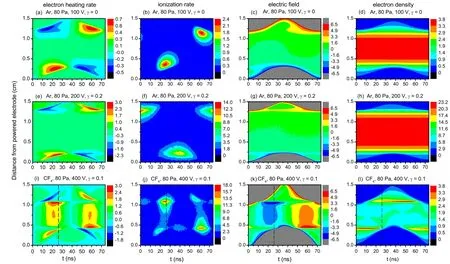
Fig.10. PIC simulation results:the spatio-temporal distributions of the electron heating rate(first column),ionization rate(second column),electric field (third column), and electron density (fourth column) in Ar and CF4 discharges driven at 13.56 MHz and 80 Pa. Reprinted with permission from Ref.[11].
The DA mode The electron power absorption mode in electronegative plasmas, e.g., the ones operated in O2, CF4,Cl2, or their mixture, is more complex. Besides the sheath region, where electrons can be heated, the electrons can gain energy from a drift field throughout the plasma bulk and from a steep ambipolar field at the edge of the collapsing sheath. As a consequence, the maxima of excitation and ionization rates can be observed across the bulk region and at the edge of the collapsing sheath, this discharge mode is DA mode, which is analyzed in details in Ref.[11](see bottom panels in Fig.10).The high drift electric field is caused by a low direct current(DC)conductivity in an electronegative CCP,where the electron is usually depleted due to electron dissociative attachment with molecules,e.g.,O2,CF4(corresponding to the formation of negative ions, e.g., O−, F−). The strong ambipolar electric field is associated with a large spatial gradient of electron density at the edge of the plasma bulk. In discharges operated at high pressure,such as in atmospheric pressure plasma jets,strong ionization and high electric fields in the bulk have been observed experimentally[37]and by simulations[38,39]due to the high electron–neutral collision frequency.
Note that in electronegative CCPs the drift field in the plasma bulk oscillates at the excitation frequency, e.g.,13.56 MHz. The(positive and negative)ions in this drift field are generally considered to be at rest (being unresponsive to the RF electric field), due to their large masses, while the lighter electrons can instantly follow the rapidly alternating RF electric field,and thereby,be accelerated to high energies,producing ionization and excitation. Consequently, in previous investigations in the RF plasma field most of the attention has been paid to the electron dynamics.[40–44]The visual appearance of such discharges commonly shows a homogeneous bright region in the central plasma bulk,with two dark sheath regions close to the electrodes.
The striation mode As the ion plasma frequency becomes comparable to or higher than the driving frequency,positive and negative ions may respond to the RF electric field with an oscillating motion, generating space charges. This may lead to the formation of stable periodic structures (‘striations’) as explained below. The electric field caused by the space charges enhances or attenuates the local drift electric field in the bulk,resulting in a spatially modulated electric field profile. The total field reinforces the response of the positive and negative ions to the alternating RF electric field by‘focusing’them into the striations. Consequently,the space charges,as well as the striated electric field are enhanced due to a positive feedback. The effect is self-amplified until a periodic steady state is established. The striated electric field results in the spatial modulation of the electron power absorption rate and,consequently,of the electron-impact excitation/ionization rate. This discharge mode is named striation mode.[45]
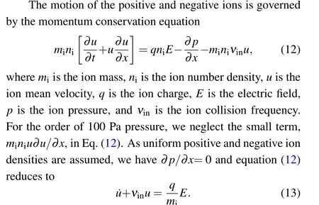
Liuet al.have reported experimental observation of selforganized striated structures of the plasma emission for the first time in CF4CCP driven at 8 MHz by phase resolved optical emission spectroscopy (PROES).[45]These observations were reproduced by PIC/MCC simulations(see Fig.11). Particularly,an analytical model indicated that the resonance between the eigenfrequency of the ion–ion system and the driving frequency is the basis for the formation of the striated structures. The motion of the positive and negative ions in an ion–ion plasma under the influence of an RF electric field can be described by a one-dimensional(1D)uniform slab ion–ion plasma model in the following.[46]
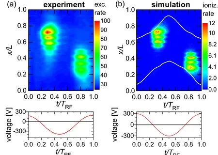
Fig.11. (a)Measured electron-impact excitation rate and(b)simulated spatiotemporal ionization rate(in units of 1021 m−3·s−1). Powered electrode is at x/L=0,grounded electrode is at x/L=1. The panels at the bottom show the discharge voltage in the experiment and in the simulation.[45]
The electric fieldEis composed of an “external” field componentEextand an“internal”field componentEint. If the positive ions (with densityn+) move a distancex+and the negative ions(with densityn−)move a distancex−,the space charges ofen+(x+−x−)anden−(x−−x+)form at the edges of the slab, respectively, as shown in Fig. 12. Note that the displacement of the ions moving towards the right is defined to be positive. The space between the two regions with space charges is filled by quasineutral plasma, wherein the electric field is given as
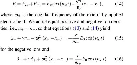
for the positive ions.
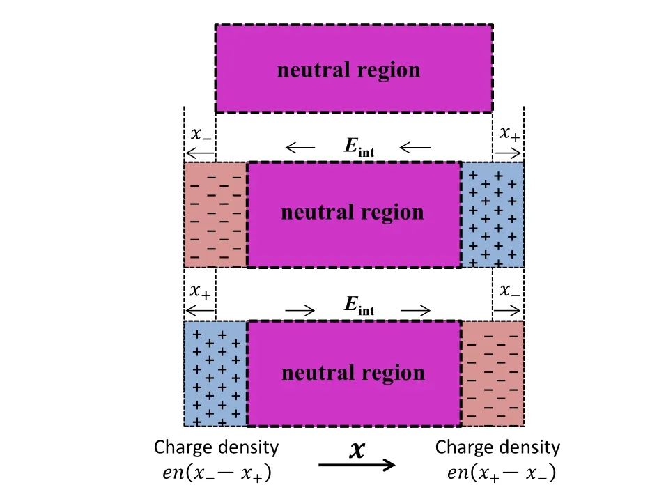
Fig. 12. Schematic of the coupled motion of the positive and negative ion system(with equal positive and negative ion densities,n+=n−)immersed in a time-varying,spatially uniform electric field Eext=E0cos(ωrft),where E0 is a constant. x± indicates the displacements of positive and negative ion groups,respectively. Note that the displacement of the ions moving towards the right is defined to be positive.

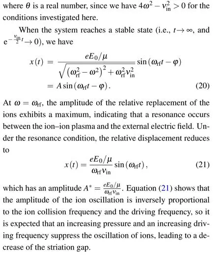
The striations were found to occur within a wide frequency range. In the striation mode, the ion density minima were found to exhibit an approximately quadratic increase with the driving frequency.[46]For a fixed driving frequency,the minima of the positive and negative ion densities(between the density peaks in the bulk) are comparable and independent of other external parameters. The striation gap, i.e., the distance between two ion density peaks, is approximately inversely proportional to the pressure, while it exhibits a weak dependence on the RF voltage and the electrode gap.[47]The striations have been observed in the PIC/MCC simulations of CCPs in O2and Cl2under some conditions,i.e.,a low driving frequency,relatively high pressure,proper voltage amplitude,etc.[48–50]This suggests that the striation is a general property of CCPs operated in electronegative gases.
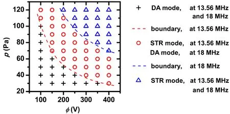
Fig. 13. Phase diagram of the DA and striation (STR) modes, determined by PIC/MCC simulations,at 13.56 MHz and 18 MHz.[47]
Mode transitions in CCPs The operation modes of RF plasmas are very sensitive to the external control parameters,and mode transitions induced by changing these control parameters have been observed and extensively studied in experiment and via numerical methods.[51–56]Godyaket al.[51]studied the transition between theα- andγ-modes in the experiment of argon and helium plasmas and observed a sharp increase of the electron density and a drop of the electron temperature by increasing the driving current, due to fast generation of low-energy electrons via secondary electron ionization. Denpoh and Nanbu[52,53]and Proshinaet al.[54]observed a transition from the bulk power deposition mode(i.e., DA mode) to the sheath power deposition mode (αmode)with decreasing gas pressure and/or increasing RF voltage in the PIC/MCC simulations of a CCP in CF4. With the same simulation approach, Yanet al.[55,56]compared the spatio-temporal distributions of the electron power absorption,as well as the ionization dynamics in electropositive argon and in electronegative SiH4capacitive discharges. They observed power absorption mode transitions induced by changing the gas pressure, the RF power, and the driving frequency. The mode transitions induced by these parameters were later confirmed by a combined method of phase resolved optical emission spectroscopy measurements and PIC/MCC simulations.[57]The underlying physics of the mode transitions in electronegative CCPs is primarily associated with the variation of the electronegativity (defined as the ratio of the negative ion to electron density) as a function of the external control parameters.[57–60]A transition between the striation and DA modes can be observed by changing either the pressure or the RF voltage(see Fig.13).[47]It is seen that for both 13.56 MHz and 18 MHz,the striation mode occurs at relatively high RF voltage or working pressure. For a given frequency,the phase boundary is found to be approximated by a constant product of the RF voltage and the working gas pressure required to generate high enough ion densities to allow the ions to react to the RF electric field,i.e.,to fulfill the resonance criterion. The critical product is found to increase as a function of the driving frequency according to the resonance criterion.
In ICPs, the discharge modes exhibit significant difference,due to distinct power coupling manners. Different from that in CCPs, Faraday’s law is the basic for the operation of ICP sources. An RF current flowing through an antenna coil induces an RF magnetic field, which generates an azimuthal induction field, causing electron heating. This system can be viewed as a transformer, i.e., the antenna coil acts as a primary circuit, while the plasma is equivalently a single-loop secondary circuit. Since the plasma is produced without an electrode,ICPs is of“electrodeless discharge”. In the following,two classic discharge modes in ICP is described.
E-mode At low RF powers the ICP sources feature a lowdensity and weak light emission. The plasma sustained in this mode is analogous to that in CCPs, in which the high-energy electrons are created by the electrostatic electric field due to the potential difference between the individual loops of the antenna coil. This mode is often called the E-mode.[61,62]It was reported by Chung and Chang[63]that the EEDF in the E mode changes from a bi-Maxwellian to a Druyvestein-like structure with increasing the gas pressure,which is similar to that in a CCP.[64]In general, there are very few studies only focusing on the E mode in ICPs.
H-mode By increasing the input power, the electrostatic electric field tends to be suppressed,while the electromagnetic field is enhanced. Meanwhile, a sudden jump in the electron density and the light emission is frequently observed at a critical voltage value. After this transition,the plasma is primarily sustained by the azimuthal RF electric field,which is produced by the oscillating magnetic field. Therefore,this mode is often named the H-mode.[61,62]The H mode is characterized by a high plasma density(usually in excess of 1×1010cm−3)and a stronger plasma emission. Note that in the H mode, there is still a small fraction of capacitive power deposition, which causes a slight fluctuation of the plasma potential. The RF fluctuation of plasma potential in ICPs can be minimized or suppressed by installing a Faraday shield.[64]
The inductive coupling efficiency is found to strongly depend on the plasma density. At relatively low density, the inductive power exhibits a linear dependence on the plasma density. The inductive power deposition reaches its maximum when the skin depth becomes comparable to the chamber dimension at a certain plasma density. At the plasma density higher than the critical density, the inductive power absorption decreases because the skin depth becomes shorter than the chamber characteristic dimension,so that the spatial scale that electromagnetic field can permeate into the plasma is restricted within the skin depth. These high-energy electrons that can overcome the ambipolar electric field are able to reach the skin layer and gain energy by interacting with the electric field in there. By contrast,the low-energy electrons cannot be heated by these strong electric fields within the skin layer,as they are generally confined in the central region by the ambipolar electrostatic potential. This is the reason why the EEDF exhibits a two-temperature profile.
Numerous numerical and theoretical studies on the E-to-H mode transition can be found in the literature.[65–70]Kortshagenet al.theoretically predicted the minimum coil current required for sustaining the H mode, and the theoretical results were in reasonable agreement with their measured values.[65]Yoonet al.developed a theoretical formula for the transition power for the E-to-H mode transition based on non-local heating theory.[66]Turner and Lieberman[67]and Cungeet al.[68]studied the mechanisms of this transition in a CW and a pulse-modulated ICP, respectively. Zhaoet al.studied the E-to-H mode transition using a hybrid fluid/Monte-Carlo model.[69]Xuet al.developed a two-dimensional(2D)fluid model that includes the effect of the circuit-matching network.[70]
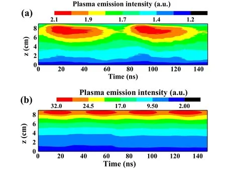
Fig.14. Space and phase resolved optical emission intensity profiles in planar coil H2 ICP at 50 mTorr(a)in the E mode(300 W)and(b)in the H mode(600 W),z is the distance from the substrate.[78]
In term of experimental study, Leeet al.observed a dramatic evolution of the EEDF in a 100 mTorr N2ICP. In the E mode, the measured EEDF exhibits a dip around 3 eV,and evolves into a Maxwellian distribution in the H mode.[71]Amorimet al.[72]and Suzukiet al.[73]observed a jump of the plasma density in an Ar ICP. Cungeet al.investigated the changes of the spatial profile of the ion density, the EEDF,and optical emission intensity at 750 nm in the CW discharge,and the time evolution of the antenna-coil current,the plasma impedance, and the magnetic field in a pulse-modulated Ar ICP.[74]Seoet al.measured the electrical characteristics of the antenna and the plasma potential during the E-to-H mode transition in an Ar ICP driven at 6.5 MHz and 19 MHz. They found that the mode transition is accompanied by a sudden drop of the plasma potential.[75,76]Gaoet al.investigated the role of a matching network in the mode transition in an Ar ICP,and found that the E-to-H and H-to-E mode transitions can be induced by adjusting the series capacitor in a Γ-type matching network for a fixed parallel capacitor.[77]They also measured the 2D plasma emission intensity during the E-to-H mode transition in a planar-coil ICP operated in Ar by an ICCD camera,and found that in the E mode the spatial profile of the plasma emission is non-axisymmetrical, while in the H mode the plasma emission intensity becomes more axisymmetrical.[78]Besides, the plasma emission intensity was found to exhibit different time dependence (see Fig. 14). In the E mode, the optical emission intensity exhibits one maximum within one RF period (see Fig. 14(a)), and this maximum is caused by high-energy electrons created by the electrostatic electric field adjacent to the coil plane on the top of the ICP chamber,which is similar to theαmode in CCPs. In the H mode, one can observe two maxima of emission intensity within each RF period (see Fig. 14(b)), due to the high-energy electrons generated by the azimuthal induced electric field,corresponding to two extrema of the RF current within one RF period. The Eto-H mode transition is usually observed during the ignition process of an ICP.[79]
4. Pulse modulated RF plasma
Compared to the conventional plasmas operated in CW mode, pulse modulated plasmas allow a more flexible control of the plasma properties by adjusting the pulse repetition frequency and the duty cycle, thus exhibiting many advantages in practical processes, e.g., an improved etch selectivity,a better etch and deposition uniformity,an optimized etch and deposition rate, etc. Therefore, pulse modulated plasmas are extremely promising tools for the next generation of semiconductor processing equipments,and relevant studies are not only of fundamental importance, but also of practical interest. A continuous and a pulse-modulated RF waveforms are schematically shown in Fig.15.
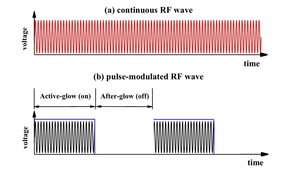
Fig. 15. Schematics of (a) a continuous RF waveform and (b) a pulsemodulated RF waveform.
Since 1980s, a large number of investigations have been implemented to explore the complex physics in pulse modulated plasmas.It has been shown that pulse modulated plasmas exhibit distinct transient and non-equilibrium characteristics in comparison to a CW discharge. The time evolution of various plasma parameters over whole pulse period has been extensively investigated in experiment and via theoretical model.Lieberman and Ashida[80]studied ICPs in low-pressure Ar and Cl2gases using a global model, finding that in Ar discharge the pulsed modulation of RF power leads to a higher time-averaged electron density than in CW mode,while in Cl2discharge, the pulsed operation can produce the same neural radical flux to the walls with a reduced average power. Ramamurthiet al.[81]examined the time evolution of charged particle densities and the electron temperature in a pulse modulated ICP using a 2D self-consistent fluid model. It was found that the warm electrons persist away from the power deposition zone, where the electron temperature exhibits a peak.Samaraet al.[82]reported the time-resolved measurements of optical emission intensity in a pulse modulated argon CCP,and found that in the case of higher power or longer afterglow duration,the integrated plasma emission overshoots more significantly at the beginning of the active period, while in the case of lower power or shorter afterglow duration,the plasma emission intensity overshoot cannot be observed. The overshoot of plasma emission intensity can be understood in the following. At the beginning of each pulse, the charge density is so low, that the RF electric field can penetrate into the central region, heating electrons intensively. As a result, the high-energy electrons generated significantly enhance the excitation rate.Mishraet al.[83]measured the temporal evolution of the plasma potential in a pulse modulated dual-frequency CCP by using an emissive probe, and found that the plasma potential follows the source pulse voltage during the whole pulse cycle. Yagisawa and Makabe[84]numerically investigated the ion energy distributions (IED) and the ion angular distributions (IAD) of different ions incident on the wafer in a pulse modulated dual-frequency CCP operated in CF4/Ar.They found that as the pressure increases, the time-averaged Ar+IED contains more low-energy component and the averaged energy of F−ion is lower than that of Ar+ion during the whole pulse period.Mishra and Economou[85]investigated the effect of pressure on the spatio-temporal evolution of a Cl2ICP and they found negative-ion density increases in the afterglow at a higher pressure due to the increasing loss of electrons via dissociative attachment process with increasing pressure, the maximum of the negative-ion wall flux, however, initially increases but then drops with increasing pressure. Xueet al.[86]studied the evolution of electron density and effective electron temperature in pulse Ar/O2mixture ICP by using a Langmuir probe,combined with a global model. They found that at the beginning of the pulse-on period, the electron density increases rapidly,while the effective electron temperature overshoots significantly.When the power is turned off,the electron density first shows a peak and then slowly decays. In addition,effects of biasing the substrate on pulse modulated discharges were reviewed by Economou[19]and Bannaet al.[87]One of the main purposes of biasing the substrate is to modulate the shape of the IEDs of ions incident on the wafer. Moreover,applying substrate bias also provides additional control parameters to enhance the etching rates and improve the etch results.For example, positive and negative ions can be alternatively accelerated toward the wafer during the etching by combining pulsed source with low frequency bias,which can mitigate the charging damages and thus improve the etch profile.[88,89]
Besides, numerous experiments, simulations, and theoretical studies have focused on the plasma decay process during the afterglow period of pulse modulated plasmas. During a diffusion-dominated afterglow at low pressure, the plasma decay process is called ‘diffusion cooling’, which describes the process that the average kinetic energy of electrons is reduced due to the diffusion loss of high-energy electrons.[90–94]The effect of electron–electron interaction (Coulomb collisions) was found to play an important role in the evolution of the EEDF as the electron temperature decreases during the late afterglow.[92,95,96]Besides,collision processes of long lifetime metastable atoms and vibrationally excited molecules can lead to electron re-heating during the afterglow.[91,97–99]Recently,experimental diagnostics and PIC/MCC simulations were combined to investigate the electron cooling, re-heating and plasma density decay processes during the afterglow of a pulsed CCP in argon.[100]In those studies,inelastic collisions(i.e., excitation and ionization processes) and Coulomb collisions were found to play different roles in the electron cooling during two different stages.
Compared to the study on the plasma decay process during the afterglow, there have been much fewer studies on the pulse ignition process of an RF plasma. During the ignition phase, it is generally recognized that due to the significant power coupled into the system the electron temperature rises sharply and overshoots its quasi-steady value, while the charged particle density increases moderately. This process features a fast change of the electrical parameters, as well as the electron power absorption mode.[13,87,101–105]As the pulse ignition is a non-equilibrium process, high-resolution timedependent diagnostics are indispensable for the determination of the dynamic evolution of plasma parameters.[79,106,107]
Gaoet al.[108]measured the temporal evolution of the input power and the electron density in a pulse-modulated ICP in argon,and examined the effects of the RF power and gas pressure. It was found that during the initial stage of the pulse-on period,the input power exhibits two maxima,and meanwhile the electron density was observed to exhibit an overshoot at a high power and a low pressure. Wanget al.[109]investigated the effect of the power-off duration on the plasma ignition process of a pulse modulated CCP operated in 450 mTorr Ar by a combination of experiments,PIC/MCC simulations,and an analytical model. They found that the time evolution of the plasma and electrical parameters during the ignition process depend strongly on the duration of the afterglow period,Toff,due to the dependence of the remaining(or initial)charge density on this parameter. In longToffcase (Toff≥100 µs), the optical emission intensity evolves with time in the same manner as the power deposition into the system, suggesting that the power is primarily absorbed by the electrons, which dissipate their energy via inelastic collisions. In shortToffcase(Toff<100 µs), theαmode dominates during the entire ignition process, as the electric field is largely shielded by the abundant charge located in the inter-electrode space. Particularly,this makes it possible to study the gas breakdown process in a pulse modulated plasma by extendingToffto a sufficiently long value.
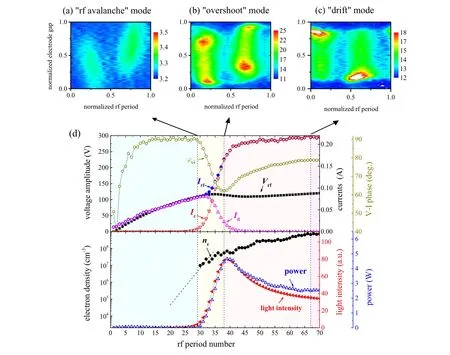
Fig. 16. Spatiotemporal plots of the measured excitation rate at the times t1 (a), t2 (b), and t3 (c), which are defined in (d). (d) shows electrical parameters,i.e.,the RF voltage and current amplitudes(Vrf and Irf),conduction and displacement currents at the discharge center(Ic and Id),V–I phase(φvi),power deposition,and plasma parameters,i.e.,electron density(ne)and light intensity as a function of the number of RF periods since the beginning of pulse.
In this way,Liuet al.[110]investigated the gas breakdown process in the same pulse CCP system withToff= 400 µs by the same set of methods. They found that the system goes through different modes of electron power absorption,i.e., ‘RF-avalanche’, ‘overshoot’, and ‘DA’ modes within the pre-breakdown, breakdown and post-breakdown phases (see Fig. 16). During the breakdown phase, the drop of theV–Iphase from 90°corresponds to the variation of the RF current period with time, which can be well understood by a current waveform model described in the following. The conduction and displacement current densities at the discharge center are
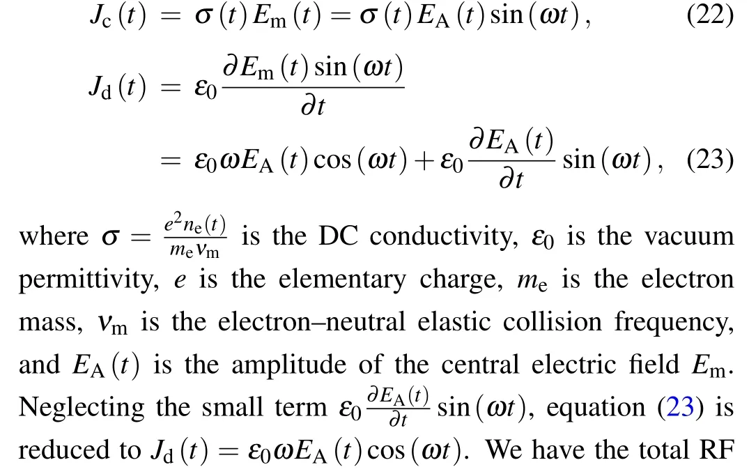


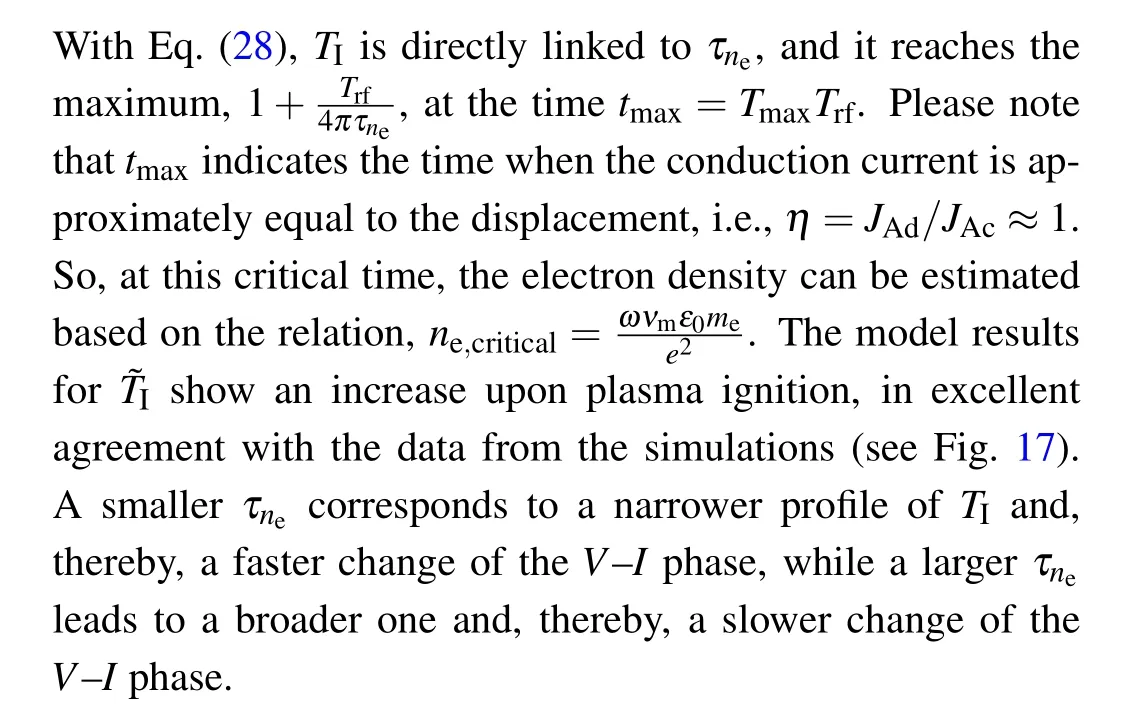
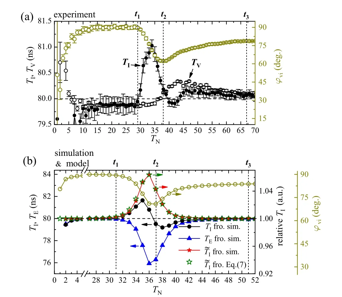
Fig. 17. (a) Periods of the measured Irf (TI) and Vrf (TV) as a function of TN. (b)Periods of the simulated Irf (TI)and Em (TE), and the relative periods [defined by Eq. (26)] of Irf (˜TI) from the simulations and Eq. (28) as a function of TN.
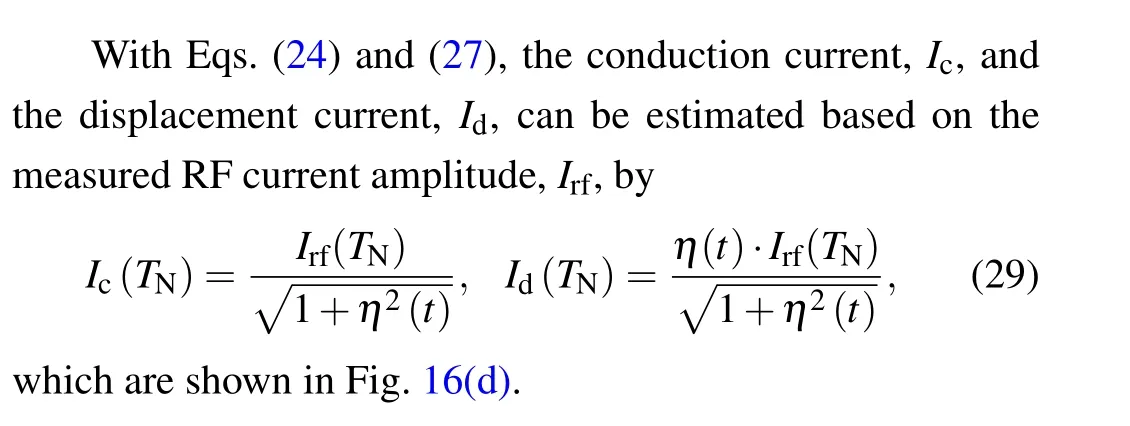
Previous studies on the ignition process of a pulse modulated CCP mostly focused on the time evolution of the axially resolved or even spatially averaged plasma parameters(e.g., the plasma emission, the electron density and temperature, etc.),[104,105,109–114]however, a 300 mm-diameter electrode is used in current semiconductor industries and, therefore, time evolution of various plasma parameters is highly radius-dependent during the ignition process in a pulse modulated plasma. Suet al.[115]studied, for the first time, the time evolution of discharge parameters at different radial positions over a 300 mm-diameter electrode during the ignition process of a pulse modulated CCP in argon by multi-fold experimental diagnostics. It was found that during the ignition phase, the plasma emission intensity, the power density, and the discharge current increase most significantly at the electrode center (see Fig. 18). At small radii, i.e.,r ≤8 cm, the emission intensity at every radius was observed to change with time in the same manner as the power density during the ignition phase. Subsequently,the profile of electron density becomes edge-high during the post-ignition phase and remains thereafter until the end of the pulse-on period. Methodologically, the synergistic diagnostics lay the foundation for extensive studies on spatiotemporal evolution of plasma ignition process under broader conditions.
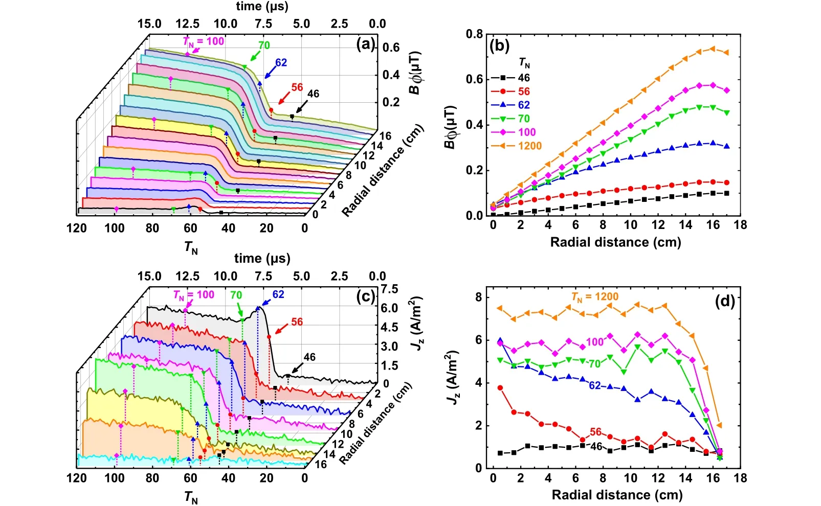
Fig.18. Time evolution of the amplitudes of(a)the azimuthal magnetic field,Bφ,and(b)the axial current density,Jz,at various radial positions during the first 120 RF cycles. The radial distributions of Bφ (b)and Jz (d)at the times corresponding to dashed vertical lines in(a)and(c).[115]
5. Electromagnetic effects and plasma uniformity in CCP
5.1. Classification of electromagnetic effects
Capacitively coupled 13.56 MHz RF plasma reactors with 100–300 mm diameter wafers have been widely used in the semiconductor equipment for etching and film deposition processes. For such plasma reactors, the instantaneous potential on the powered electrode is almost independent of the radial position since the electrode diameter is negligible as compared to the wavelength of the electromagnetic wave.Therefore,an electrostatic approximation neglecting the effect of the magnetic field generated by the time-varying electric field can be used to calculate the electromagnetic field in the plasma.[9,116,117]Nowadays, large-area CCP reactor driven at the VHF has received growing attention due to various benefits, particularly for the solar cell and flat panel display industries. On one hand, a larger reactor is needed to accommodate a larger wafer, thus improving the throughput. On the other hand, the use of higher excitation frequencies can i) enhance the etching/film deposition rate by raising the ion flux impinging on the substrate,and ii)minimize the substrate damage by lowering the mean ion energy.[118,119]When the excitation frequency of the RF source becomes high enough,however, electromagnetic effects will come into play and negatively affect the plasma uniformity.[20,21]Over the past two decades, the electromagnetic effects in VHF CCPs have been investigated by a variety of approaches, such as analytical models,[120–124]numerical simulations,[117,125–134]and experiments.[118,119,135–139]Overall,the physical reason causing the plasma non-uniformities can be divided into four categories:
i)Standing wave effect When the excitation frequency of the RF source is sufficiently high so that the half-wavelength of the electromagnetic surface wave becomes comparable or smaller than the electrode size,constructive interference of the oppositely traveling waves propagating along the sheath-bulk plasma interface from the electrode edge to the center will take place, causing the so-called standing wave effect (SWE). A schematic of the electromagnetic wave propagation in a VHF CCP reactor is shown in Fig.19.The presence of the SWE will lead to enhancements of the electric field and power deposition at the reactor center,thus causing a center-peaked distribution of the plasma density. Figure 20 shows that as the driving frequency increases the plasma density experiences the transition from a flat,center-high,to a multimodal radial profile,indicating a shrinking electromagnetic wavelength. In a VHF CCP,there are two distinct electromagnetic modes (the first even mode withEz(r,−z) =Ez(r,z) and the first odd mode withEz(r,−z)=−Ez(r,z))that are sufficient to determine the electromagnetic fields inside the reactor except the region close to the sidewalls.[121,140]The inter-electrode RF voltage SWE is mainly associated with the first even mode, which can occur in both geometrically symmetric and asymmetric discharges.

Fig. 19. Schematic of the electromagnetic wave propagation in a VHF capacitive discharge.
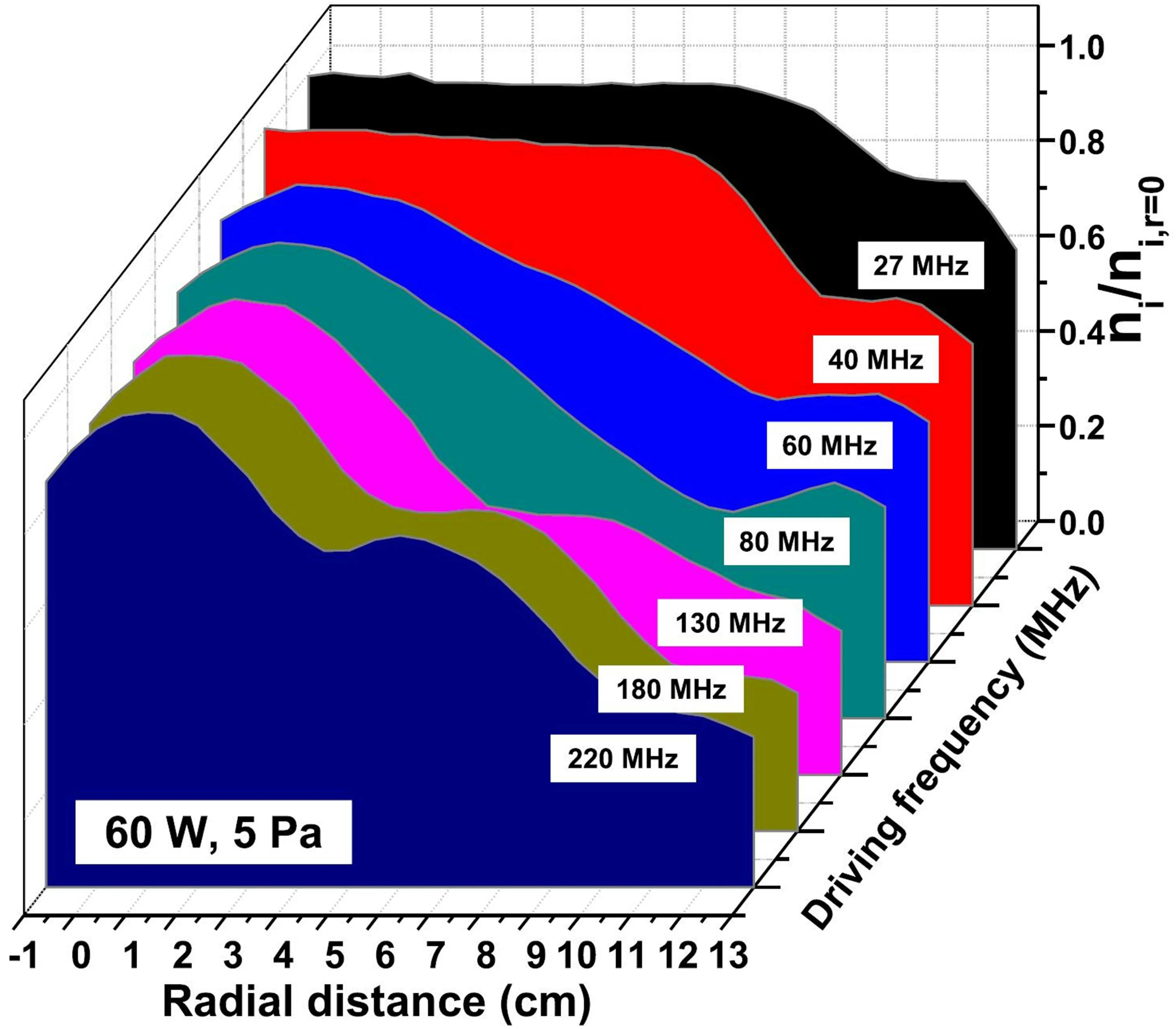
Fig. 20. Measured radial profiles of plasma density along the mid-gap of the electrodes in capacitive argon discharges driven at different driving frequencies,at 60 W and 5 Pa. All density curves are normalized to their radial maxima. Reprinted with permission from Ref.[137].
ii) Telegraph effect Different from the first even mode,the first odd mode can be excited only in a geometrically asymmetric CCP reactor. Due to the unequal areas of the powered and grounded electrodes, perturbation of the plasma RF potential dominated by the first odd mode will produce a net radial current in the bulk plasma to maintain the RF current continuity.[121,140]The propagation of such plasma potential perturbation is analogous to a quasi-TEM wave in a lossy transmission line,so it is called the telegraph effect. Since the perturbation ofEzdominated by the first odd mode is an odd function of axial positionz, i.e., the sheath voltages adjacent to both electrodes are equal and opposite,the telegraph effect does not affect the total inter-electrode RF voltage, which is solely determined by the SWE.
iii) Skin effect When the plasma density is sufficiently high so that the skin depth of the electromagnetic wave penetrating into the plasma becomes comparable or smaller than the plasma thickness,an induced radial electric field is formed at the sheath–bulk plasma interfaces, causing a maximum inductive power deposition at the electrode edge.[123,125]With increasing the applied voltage, the inductive heating caused by the skin effect becomes enhanced and the discharge might experience a local or global E-to-H transition depending on the gas pressure.[122–124]
iv)Edge effect It is well known that the electrostatic edge effect associated with the enhancement of the electric field close to the electrode edge often appears in the conventional 13.56 MHz CCPs. Operated at the VHF domain, an electromagnetic edge effect will also occur due to the abrupt change of the permittivity around the electrode edge.[120]In a geometrically asymmetric discharge,unlike the first even and odd modes that can be propagated radially inwards from the reactor edge,the high-order even and odd modes are radially evanescent,which produce a sharp maximum in the power deposition at the reactor periphery.[120,121]
5.2. Nonlinear standing wave excitation
While the underlying physics of the SWE dominated by the fundamental frequency has been well understood by the studies aforementioned,[117–140]the important nonlinear effects were inevitably ignored. It has long been recognized that in low-pressure, geometrically asymmetric CCPs, highfrequency nonlinear plasma series resonance (PSR) oscillations can be self-excited due to the interaction between the capacitive sheath and the inductive bulk.[141–152]The lowresistance feature of such an RLC-like resonance allows the discharge to be sustained with quite a small voltage at the resonance frequency, while a sufficiently high current is generated between the electrodes. Although the fundamental driving frequency is generally much lower than the PSR frequency, the higher harmonics produced by the nonlinear sheath motion can be strengthened at or near the series resonance frequencies,thus drastically enhancing the local electron power deposition.[142,145,146]Since these higher harmonics have much shorter wavelengths than the fundamental frequency,they are easier to form a standing wave.
The important role of the higher harmonics in affecting the plasma nonuniformities was emphasized by Upadhyayet al.[153]and Sawadaet al.[154]By a combination of experimental measurements and high-resolution, self-consistent 2D fluid simulations, the authors concluded that the presence of higher harmonics is strongly correlated with the occurrence of the sharp central peak of the plasma density.Milleret al.[155]observed distinct differences in the spatial distributions and harmonic content of RF fields in the plasma at the different frequencies(13.56 MHz,60 MHz,and 176 MHz). Their results suggested that interaction between the plasma and the RF excitation circuit may strongly influence the structures of the magnetic fields.
Recently, Liebermanet al.[156]developed a 1D nonlinear radial transmission line model for a highly asymmetric cylindrical discharge to address the coupling of the series resonance-enhanced harmonics to the standing waves. The model assumed a fixed uniform plasma slab with a single nonlinear homogeneous collisionless (ion) sheath at the powered electrode,which is driven at the edge(r=R)by a RF source having resistanceRTand voltageVrf=Vrf0cosωtthrough a large blocking capacitorCB(see Fig.21). Radial propagation of the electromagnetic waves in an axisymmetric parallel-plate CCP can be described by Maxwell’s equations
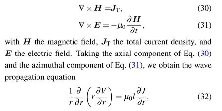
whereris the electrode radius,Vis the RF voltage of the grounded electrode with respect to the powered electrode,µ0is the vacuum permeability,lis the interelectrode gap, andJis the total axial current density. The radial profiles of harmonic RF voltage and current can be determined by coupling Eq.(32)with the following current balance equation(33)and the electron momentum balance equation(34):

where∂Σ/∂tis the displacement current,Ji0is the ion current,Je0is the electron random thermal current,Vsis the sheath voltage,Teis the electron temperature,meis the electron mass,dis the plasma thickness,VBis the self-bias, andνenis the effective electron collision frequency. The theoretical model predicted that the spatial wave resonances of self-excited nonlinear higher harmonics can lead to a significant center-peaked profile in the electron power deposition, even at a relatively low frequency of 30 MHz.

Fig. 21. A nonlinear radial transmission line model of an asymmetrically driven RF capacitive discharge.
Recently, Zhaoet al.[157]reported the first experimental evidence of nonlinear standing waves excited by PSRenhanced harmonics in VHF(100 MHz)CCP reactors by using a high-frequency magnetic probe. Experimentally determined spatial structures of the harmonics of the magnetic field were compared with simulations based on the nonlinear transmission line model described by Eqs. (32)–(34), showing a reasonably good agreement (see Fig. 22). At low pressure,higher harmonics enhanced by the PSR were found to induce spatial wave resonances,with voltage and current peaked onaxis, leading to center-high plasma density. Besides, it was observed that the excitation of the higher harmonics was suppressed at higher pressures,resulting in improved plasma uniformity.

Fig. 22. Experimental data (points) and simulation predictions (lines) for discharges driven at 13.56 MHz (left) and 100 MHz (right) at 3 Pa, for a fixed power of 80 W: radial distributions of the harmonic magnetic field Bϕ,n (a), (b), the harmonic voltage Vn (c), (d), and the harmonic current Jn (e), (f). All harmonic amplitudes(n=1–5)are normalized to the radial maxima to obtain a clearer view of the harmonic structures. Reprinted with permission from Ref.[157].
The nonlinear radial transmission line model was incorporated into a 2D fluid code by Kawamuraet al.[158]to study the electromagnetic effect in a low-pressure electronegative chlorine discharge. It was found that at higher applied frequencies, the higher harmonics contribute significantly to the center-high nonuniformity due to their shorter plasma wavelengths. Wenet al.[159]studied the dynamics of series resonance and SWEs in a dual-frequency CCP by using the nonlinear radial transmission line model incorporated with a Child law sheath. A more advanced nonlinear electromagnetic model with radially- and time-varying sheath widths was also developed to study the symmetric and antisymmetric modes in an asymmetrically excited cylindrical discharge.[160]Liuet al.[161]coupled the nonlinear radial transmission line model with an analytical collisionless or collisional (ion)sheath model and a 2D bulk plasma fluid model to determine the symmetric and antisymmetric mode surface waves and the electron power deposition in asymmetric cylindrical capacitive discharges,with the stochastic and Ohmic sheath heating being taken into account. The nonlinearly excited harmonics obtained by the collisionless and collisional sheath models for a wide pressure range were compared and discussed.More recently, the effects of the plasma density nonuniformity and RF power on the propagation of electromagnetic surface waves and electron power deposition were examined by Zhouet al.[162]Simulation results indicated that under the assumption of the radially uniform plasma density in a CCP discharge, the self-excitation of higher harmonics at the radial center can be underestimated(see Fig.23).
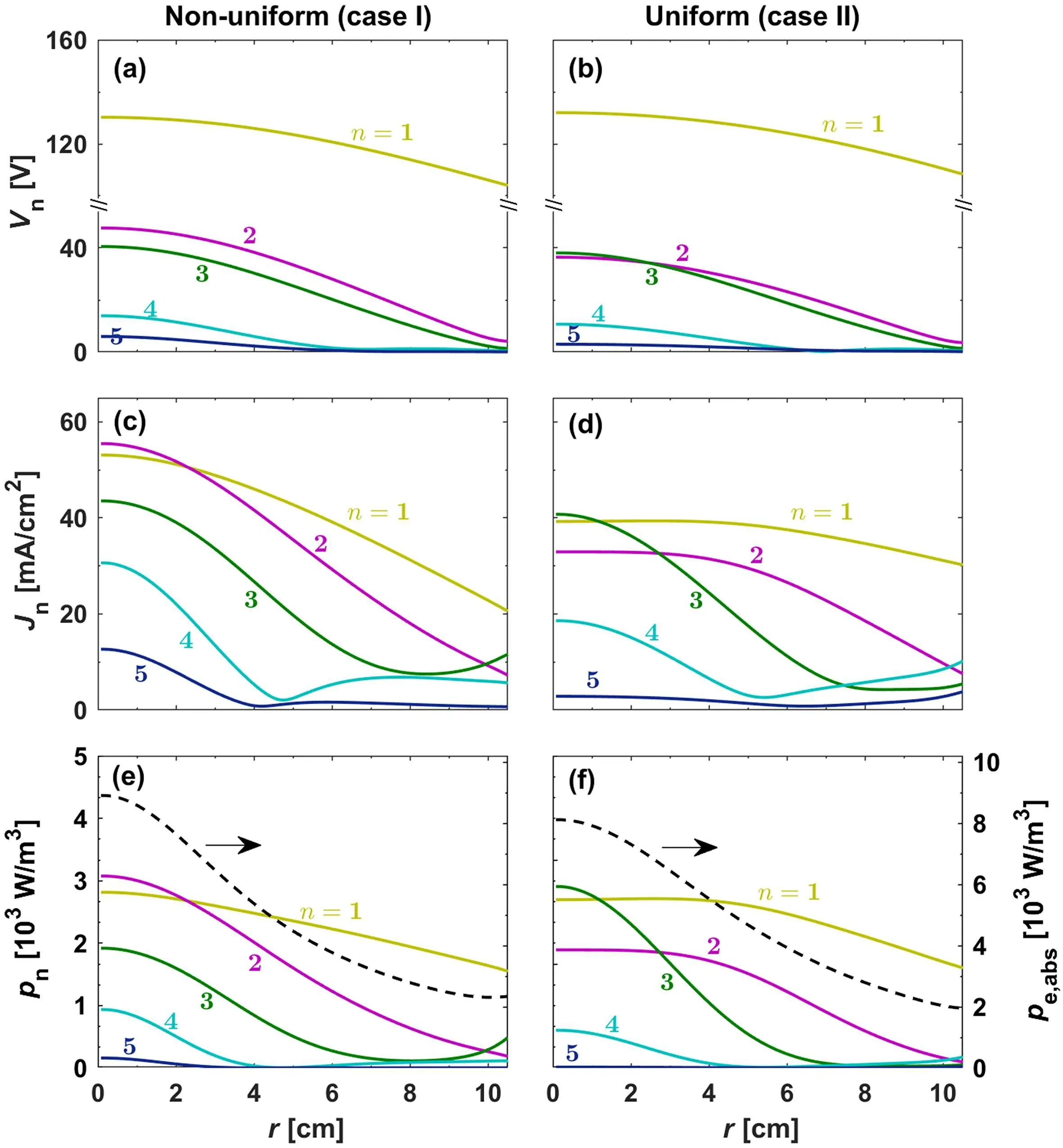
Fig.23. Radial distributions of the harmonic voltage Vn (top row),the harmonic current density Jz,n (middle row), and the harmonic electron power absorption density pn (bottom row) for the non-uniform (left column) and uniform(right column)plasma density profiles. Note that the dashed black lines in (e) and (f) present the radial profiles of the total electron power absorption density pe. The colored numbers in each panel indicate the harmonic order n.[162]
5.3. Methods to optimize the plasma uniformity
Due to continuous growth in both the driving frequency and the wafer size, plasma non-uniformities caused by the standing wave effect have become a major challenge in the material etching and film deposition processes. To optimize the plasma uniformity, several methods have been put forward, such as the use of specially shaped electrodes,[163–167]phase-shift control,[168–170]the use of the dual-frequency or multi-frequency source,[133,138,139,171,172]discharge symmetry control,[173,174]etc.
The use of specially shaped electrodes, e.g., Gaussianshaped electrode, stepped electrode, multi-electrode, graded conductivity and segmented electrodes,etc.,has proven to be effective methods to improve the plasma uniformity in the semiconductor industries.[163–167]By applying two RF sources with the same excitation frequency on separate electrodes, it was shown that plasma uniformity can be optimized by tuning the phase shift between two sources over a wide range of discharge parameters.[168–170]This is the so-called “phase-shift control” method. Besides, the dual-frequency[138,139,171,172]or multi-frequency[133]source can be used as an alternative way to optimize the plasma uniformity. By using a two-dimensional plasma model, Beraet al.[171]found that the plasma distribution can be effectively controlled by mixing VHF source powers at 60 MHz and 180 MHz. Also,it was demonstrated experimentally that in a dual-frequency 90 MHz/180 MHz discharge,the radial profile of plasma density could be controlled and optimized by adjusting the amplitude ratio of the low-frequency to high-frequency voltage.[138]By introducing a low-frequency(2–8 MHz)source to a VHF(100 MHz)CCP,Zhaoet al.[139]investigated the dependence of the radial profile of plasma density on the low-frequency source for two typical cases, i.e., the two RF sources applied on one electrode(case I)and separate electrodes(case II).For case I,it was demonstrated that the SWE could be suppressed by the strong modulation dominated by the low-frequency source, and consequently, the plasma uniformity was improved (see Fig. 24(a)). The modulation effect was observed to become stronger with increasing the low-frequency voltage or decreasing the low-frequency. For case II, it was shown that the center-high density profile dominated by the SWE can be compensated by the electrostatic edge effect dominated by the low-frequency, the latter of which tended to be enhanced by increasing the low-frequency(see Fig.24(b)). The method to optimize the plasma uniformity by balancing the SWE with the edge effect was also examined recently by Hanet al.[172]in a larger CCP reactor with 450 mm diameter electrodes. Using a fast 2D axisymmetric fluid-analytical plasma reactor model,Kawamuraet al.[133]studied the electromagnetic effects in multi-frequency (2 MHz/60 MHz/162 MHz) CCP in argon.A significant SWE characterized by a plasma density peak at the center was observed at 162 MHz. Besides,the plasma uniformity can be improved by adding 2 MHz power source to a 60 MHz discharge or adding a 162 MHz source to a dualfrequency 2 MHz/60 MHz discharge.
The plasma uniformity can also be tuned by adjusting the discharge asymmetry, which can be formed either geometrically,[175–177]electrically,[178–181]or magnetically.[182–185]In a large-area, dual-frequency(40.68 MHz/81.36MHz) CCP in hydrogen, Sch¨ungelet al.[181]demonstrated that the lateral inhomogeneities caused by SWEs can be mitigated by changing the discharge symmetry via the electrical asymmetry effect (EAE), i.e., by tuning the phase shift between the two applied frequencies. However, the underlying mechanism of the influence of discharge symmetry on the nonlinear harmonics and standing waves was not clarified. To this end, Zhaoet al.[174]experimentally investigate the influence of the EAE on the nonlinear standing waves induced by the PSR-enhanced harmonics in a geometrically asymmetric, capacitive argon discharge driven by two consecutive harmonics(30 MHz and 60 MHz)with an adjustable phase shift. To bring the effects of nonlinear harmonic excitations on the plasma uniformity into clear focus,a hairpin probe was used to determine the radial distribution of the electron density while a high-frequency magnetic probe was used to measure the radial distributions of the harmonic magnetic field and harmonic current density (see Fig. 25). It was found that the geometrical asymmetry of the discharge can be compensated electrically via the EAE and, thereby,the DC self-bias and the discharge symmetry can be adjusted accordingly. Since the nonlinear PSR oscillations and the harmonic excitations are sensitive to the discharge asymmetry,the nonlinear standing wave can be suppressed by adjusting the symmetry of the discharge, thus resulting in an improved plasma uniformity.
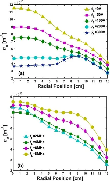
Fig.24. The effects of low-frequency voltage φL (a)and low-frequency fL(b) on the radial profile of the plasma density along the midplane between two electrodes in dual-frequency CCPs. In (a), both the high-frequency(100 MHz, 50 V) and low-frequency (4 MHz, 0–300 V) sources were applied on the bottom electrode (case I), and the gas pressure was 8 Pa. In(b),the high-frequency(100 MHz,50 V)source was applied on the bottom electrode while the low-frequency(2–8 MHz,300 V)source was applied on the top electrode(case II),and the gas pressure was 20 Pa.[139]
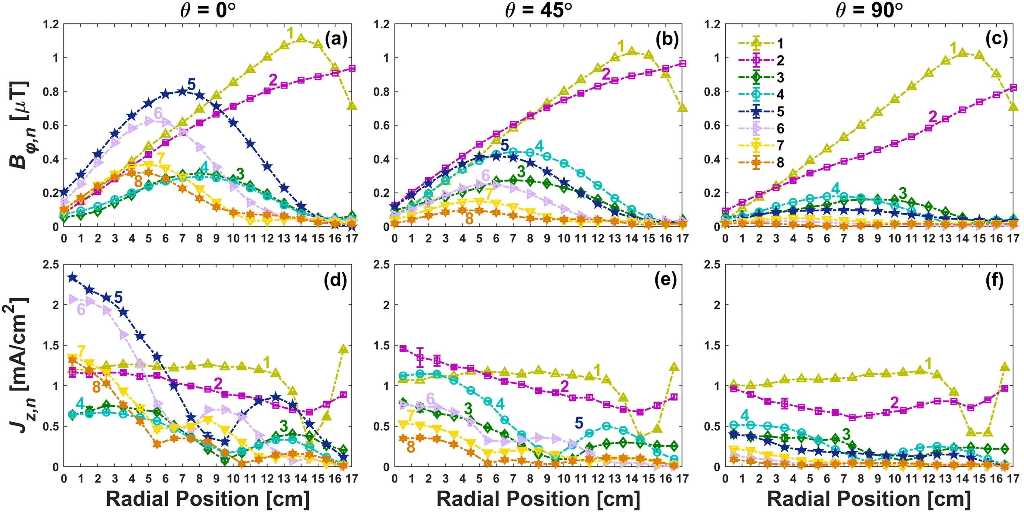
Fig.25. The influence of the electrical asymmetry effect on the nonlinear standing waves excited by the PSR-enhanced higher harmonics in a geometrically asymmetric,low pressure CCP reactor driven by two high frequency sources(30 MHz and 60 MHz)with an adjustable relative phase shift,θ. The first and second rows show,respectively,radial distributions of the harmonic magnetic field and the harmonic current density at different θ: θ =0◦(left column),θ =45◦(middle column),and θ =90◦(right column). The numbers indicate the harmonic orders in each panel.[174]
6. Conclusions and outlook
In this paper,we review the research progress on several topics that have been achieved in RF plasma field over the past several decades. The topics, electron heating and plasma operation mode, are of the fundamental issues, and the relevant investigations are expected to provide the basis for understanding the dependence of macroscopic plasma parameters on external control parameters,as any change in the plasma parameter (e.g., electron density, temperature) is the reflection of microscopic electron dynamics. Especially, the fundamental study makes it possible to realize a knowledge-based control and optimization of plasma parameters, e.g., concentrations of charged particles and radicals,ion energy distribution,etc.,which are favorable for practical plasma-based material processing.
The continuously developing semiconductor and photovoltaic technology sets even higher requirements for RF plasma sources, and apparently, improving the controlling level of plasma parameters becomes increasingly important.To this end,some new electrical control techniques of plasma sources have been developed,such as pulse modulation of RF power, and multi-frequency excitation of plasma, which have been widely adopted in etching processing of today’s semiconductor manufacturing. Last decade, researchers proposed a promising concept of electrical control, i.e., voltage waveform tailoring (VWT), which allows to realize a high-quality independent control of the ion energy and flux on the substrate.So far,most of the investigations,however,are all about the axial profile of plasma parameters between two electrodes,which restricts utilization and popularization of this technique.Particularly,some new knotty problems might arise when the VWT technique is applied in a 300 mm-diameter electrode CCP, e.g., plasma uniformity issue, geometrical asymmetry effect, etc. So, extended study towards the radial profile of plasma parameters under the VWT excitation is of practical importance.
The other two topics reviewed in this article, i.e., pulse modulated plasma,electromagnetic effects,have been mostly studied separately. Specifically, in previous studies of pulsed plasmas researchers have been concerning more about the fundamental process,and thus,the 1D profile of plasma parameters has been more emphasized. While on the study of electromagnetic effects, more attention has been paid to the plasma radial profile in continuous-wave discharge. In current etching processing for semiconductor manufacturing, the plasma source is usually driven by a VHF power supply,which is frequently pulse-modulated. However,there is very few relevant investigations neither in experiment, nor in simulation. The plasma uniformity has become an urgent problem when the electromagnetic effect is combined with pulse modulation of RF power,and thereby,should be addressed in the immediate future.
Methodologically,advanced numerical methods,theoretical model, as well as experimental diagnostic are also essential and should be developed to better serve for these investigations. For example, the commonly-used electrostatic PIC/MCC model should consider the motion of charged particles in electromagnetic field by solving Maxwell’s equations to address the electromagnetic wave propagation problem in VHF CCP. In experiment, some advanced diagnostic tools,e.g., high-frequency magnetic probe and advanced spectroscopic technology, are indispensable, whose results, on the other hand,can be used to validate the simulation results.
In general, the fundamental study of RF plasmas should be geared to the needs of practical industrial application. The selection of research topics should be motivated by the issues encountered in industrial applications.
Acknowledgement
This work has been financially supported by the National Natural Science Foundation of China (Grant Nos. 11935005 and 11875100).
- Chinese Physics B的其它文章
- Direct measurement of two-qubit phononic entangled states via optomechanical interactions
- Inertial focusing and rotating characteristics of elliptical and rectangular particle pairs in channel flow
- Achieving ultracold Bose–Fermi mixture of 87Rb and 40K with dual dark magnetic-optical-trap
- New experimental measurement of natSe(n,γ)cross section between 1 eV to 1 keV at the CSNS Back-n facility
- Oscillation properties of matter–wave bright solitons in harmonic potentials
- Synchronously scrambled diffuse image encryption method based on a new cosine chaotic map

