Multiple bottle beams based on metasurface optical field modulation and their capture of multiple atoms
Xichun Zhang(张希纯) Wensheng Fu(付文升) Jinguang Lv(吕金光) Chong Zhang(张崇)Xin Zhao(赵鑫) Weiyan Li(李卫岩) and He Zhang(张贺)
1State Key Laboratory of High Power Semiconductor Lasers,Changchun University of Science and Technology,Changchun 130022,China
2State Key Laboratory of Applied Optics,Changchun Institute of Optics,Fine Mechanics and Physics,Chinese Academy of Sciences,Changchun 130033,China
3The First Military Representative Office of the Army in Changchun,Changchun 130033,China
Keywords: metasurface,bottle beam,optical tweezers,Pancharatnam–Berry phase
1. Introduction
A bottle beam is a special hollow beam with a closed dark field in three dimensions along the propagation direction. This dark field is a closed region surrounded by highintensity light.[1,2]Bottle beams have a wide range of applications in optical tweezers,[3,4]laser catheters,[5]and optical micromanipulation.[6]In particular,when a bottle beam is applied to optical tweezers, it can stably capture and manipulate microscopic particles. Optical tweezers technology using a bottle beam as the light source has the advantages of non-contact and no strong light directly irradiating on the manipulated particles, so the particles can be manipulated without damage. Since 1987, various methods have been tried to generate bottle beams,such as the ring-slit-lens method,[7]the axial prism-lens system method,[7]the double-beam interferometry method,[9]the optical holography method,[10]and the phase plate method.[11]
With the Pancharatnam–Berry (P–B) phase metasurface proposed by Prof.Cappasso of Harvard University in 2012,[12]the study of metasurfaces has become a research hotspot in the international academic community today. The P–B phase metasurface usually consists of subwavelength-sized grating,and rectangular or elliptical anisotropic units arranged in a particular pattern. By rotating these units to a certain angle, the phase of the incident light can be changed locally,so that the amplitude, phase and polarization of the incident or reflected light can be manipulated arbitrarily,[13–17]thereby shaping the wavefront of the beam. Therefore, such optical devices can replace or improve conventional optical elements.[18–21]An important application in this regard is optical lenses based on metasurfaces. In 2019, Wuet al.designed a metasurface to generate 3D hollow spots and simulated the light field distribution of 3D hollow spots at different wavelengths.[22]In 2021,Liet al.integrated optical tweezers and optical spanners, using a metasurface to generate both optical tweezers and optical spanners. They enhance the application of metasurfaces as optical lenses.[23]For example,a metallic and dielectric-typebased metasurface has been used to focus light into the near or far field,[21–26]and even to achieve achromatic effects in the visible or infrared wavelength range.[27–29]
In this paper, we designed a metasurface with silicon dioxide (SiO2) as the substrate and titanium dioxide (TiO2)nanopillars as the unit. The incident light field passes through the metasurface to generate spherical waves and Bessel beam interference,[30]resulting in multiple high-intensity and micron-sized bottle beams. Compared to conventional optical systems,this system is simple and highly integrated. The lateral and longitudinal inner diameters of the generated bottle beam are significantly reduced. And the paper analyses the ability of the multiple bottle beams to act as arrayed optical tweezers,demonstrating their ability to capture multiple ytterbium atoms.
2. Metasurface design principles
2.1. Optical system design
As shown in Fig. 1, the design of the metasurface optical system is presented in this paper. The incident beam of the He–Ne laser is collimated using a collimator.The beam passes through a polarizer to produce linearly polarized light and then passes through aλ/4 waveplate to produce a left-rotating circularly polarized beam (the angle of the fast axis of theλ/4 waveplate needs to be 45◦to the polarization direction of the polarizer to produce a left-rotating circularly polarized beam).Finally, the beam is incident on the metasurface to produce multiple bottle beams, and the spot is observed using a CCD camera.
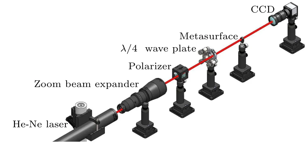
Fig.1. A schematic diagram of the optical system.
2.2. Metasurface nanopillar design
When the circularly polarized light irradiates the P–B phase metasurface, the outgoing light will consist of two components: left-handed circularly polarized light and righthanded circularly polarized light. And the component of the outgoing light with the opposite spin direction of the incident light will carry the geometric phase delay (±2θ), whereθis the nanopillar unit rotation angle and±1 represents lefthanded circularly polarized(LCP)and right-handed circularly polarized(RCP)light,respectively.
With regard to the substrate of the metasurface, high transmittance at the operating wavelength is required to reduce losses and improve the efficiency of the device. To build metasurface nanostructures,materials with both high transmittance and a high refractive index are required. For the above reasons,titanium dioxide(TiO2)nanopillars arranged on a silicon dioxide(SiO2)substrate are chosen in this paper. Both materials have high transmittance at 632.8 nm, where TiO2meets the two conditions of a sufficiently high refractive index and enough low loss rate in the working wavelength. The simulations were carried out using the commercial software package“finite-difference time domain(FDTD Solutions)”(Lumerical Inc.). When calculating the transmittance, polarization conversion and Pancharatnam–Berry phase of the cell, periodic boundary conditions are used along thexandyaxes and the perfectly matched layer (PML) along thez-axis. The refractive indices of the SiO2substrate and TiO2cell are set to 1.46 and 2.58, respectively. To design the working wavelength of the metasurface as 632.8 nm, the metasurface nanopillar unit is shown in Fig.2(a),and its lengthl,widthw,and heighthare selected as 377 nm, 87 nm,and 600 nm, respectively. Its polarization conversion efficiency, as well as transmittance, are higher than 85%. Here,the polarization conversion efficiency is defined as the ratio of the intensity of the transmitted light opposite the incident light rotation to the intensity of the incident circularly polarized light. And its P–B phase delay with the rotation of the nanopillar can cover 0–2π, so that it can effectively control the wavefront. The simulation results are shown in Fig.2(b).
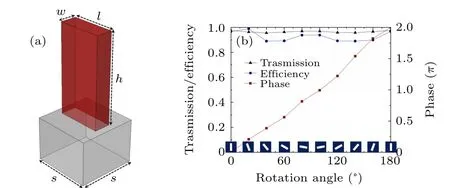
Fig. 2. A schematic diagram of the nanopillar unit and the relationship between its rotation angle and related parameters. (a)A schematic diagram of a single nanopillar unit. (b) The relationship between the rotation angle of the nanopillar unit and the transmittance (triangular line), polarization conversion efficiency(circular line),and P–B phase(square line).
2.3. Phase distribution of the metasurface
In this paper,the metasurface comprises three parts from inside to outside: an inner ring, an opaque ring obstacle, and an outer ring,as shown in Fig.3,and their radii areR1=4µm,R2=6 µm, andR3=2 µm, respectively. For the inner ring part, the metasurface elements are arranged according to the hyperboloid phase distribution. Under the irradiation of lefthanded circularly polarized (LCP) light, the generated waves interfere with the phase length in the focal plane, forming a focused light and acting as a convex lens. The arrangement is given by the following expression:[12]

whereϕ1represents the phase delay,λis the incident wavelength,fis the given focal length,xandyare the transverse and longitudinal coordinates of the nanopillar centroid,respectively,andRis the metasurface radius. The phase delay can be achieved by rotating the nano cells based on the P–B phase principle,and the expression for the rotation angle of the rectangular nanopillar on the metasurface is

In this paper,the metasurface radiusR4=12µm,the focal distancef=10 µm in the inner ring part, and the angleα=0.75 in the outer ring part (Fig. 3), composed of 1178 TiO2units. Its nano unit rotation angle is given by Eqs. (2)and(4).
Figures 4(a)–4(c) show two-dimensional schematic diagrams of the inner and outer ring parts and the ring obstacle metasurface, respectively. Schematic diagrams of the spherical wave and Bessel light distribution along the optical axis direction are shown in Figs. 4(d) and 4(e), respectively. The spherical wave generated in the inner ring part of the metasurface is coherently superimposed with the Bessel light generated in the outer ring part. Multiple high-intensity bottle beams are formed in the region of coherent superposition of the two beams. As seen in Fig. 4(f), four complete bottle beams are produced. Figures 4(g)–4(i) show the line distribution schematic of Figs.4(d)–4(i),respectively.

Fig.3. A schematic diagram of the ring obstacle metasurface. The inset part is an enlarged view of the metasurface.

Fig. 4. The inner and outer rings of the metasurface, light field distribution and linear distribution. (a) A schematic diagram of the inner ring part of the metasurface.(b)A schematic diagram of the outer ring part of the metasurface.(c)A two-dimensional schematic diagram of the annular obstacle metasurface.(d)Optical field distribution of the spherical wave generated in the inner ring part. (e)Light field distribution of the Bessel light generated in the outer ring part. (f)Light field distribution of the bottle beam. (g)Line distribution of the spherical wave(d). (h)Line distribution of the Bessel light(e). (i)Line shape distribution of the multiple bottle beam(f).
3. Analysis and discussion
3.1. Bottle beam light field distribution
In this paper,a metasurface with a radius of 12µm is designed and the incident light is LCP light. After simulation,four complete bottle beams are produced,labeled as Nos.1,2,3, and 4 in this paper. The light field distribution of its beam propagation direction is shown in Fig. 5(a), and the crosssectional light intensity of the multiple bottle beams at the propagation distances of 9.17 µm and 11.24 µm (at the focal plane of the bottle beams of Nos. 2 and 3) are shown in the small figure of Fig.5(a). These two bottle beams were selected,and the transverse full-widths at half-maximum of the two beams were measured to be 0.46µm and 0.6µm,and the longitudinal full-widths at half-maximum were 0.85 µm and 1.12µm,respectively(as shown in Figs.5(b)–5(d)). Here,the lateral and radial full-widths at half-maximum (FWHM) are defined as the distance between two points at half of the maximum intensity of the light field along thexandzdirections of a single bottle beam.
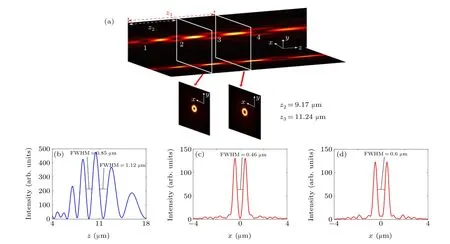
Fig.5. A light field diagram and a linearity diagram of the multiple bottle beams. (a)Light field distribution in the beam propagation direction(z-direction)of the multiple bottle beams. The two insets show the transverse light field distributions at 9.17µm and 11.24µm,respectively. (b)Line distribution of the light intensity in the z-direction of the beam of the multiple bottle beams. (c),(d)Line distribution of the x-direction light intensity at 9.17µm and 11.24µm.The longitudinal full-widths at half-maximum(FWHM)of the bottle beams of 2 and 3 are 0.85µm and 1.12µm,respectively,and the transverse full-widths at half-maximum(FWHM)are 0.46µm and 0.6µm,respectively.
3.2. Effect of different aperture ring diaphragms on the number of bottle beams
The number of generated multiple bottle beams can be changed when the size of the annular obstacle on the metasurface. In this paper,the radius of the metasurface is 12µm,and we control its outer ring sizeR3=2µm,and change the size of the ring obstacle so that the ring obstacle sizes areR2=5µm,6 µm, and 7 µm, respectively (R2corresponds to Figs. 6(a)–6(c), respectively). Through simulation, from the figure, it is easy to find that the number of bottle beams is 2,4,and 5 from left to right, respectively. When the focal length of the metasurface is constant,the size of the generated light field can be reduced by increasing the radius of the metasurface,allowing the light to be more focused.Therefore,when the inner ring of the focused light generated from Figs.6(a)–6(c)gradually decreases,the size of the focused light gradually increases. The interference range between the focused light and Bessel light gradually increases,and the number of bottle beams generated increases in turn. Therefore, the number of bottle beams can be changed by controlling the size of annular obstacles on the metasurface. Then,the number of generated bottle beams can be designed according to the planned number of particles to be captured.

Fig. 6. The two-dimensional light field distribution along the beam propagation direction of the annular obstacle metasurface with different aperture sizes. From left to right,the annular obstacle dimensions are(a)R2=5µm,(b)R2=6µm,and(c)R2=7µm.
3.3. Effect of varying the x-component of the nanopillar unit on the shape of the bottle beam
When we change thex-directional component of the rotation angle of the nanopillar cell, the shape of the resulting bottle beam is changeable.Using a rounded corner rectangular opaque obstacle with a hollow circle in the center(R1=4µm,R4=12 µm), as shown in Fig. 7, the metasurface is divided into three parts, numbered 1, 2, and 3 in Fig. 7. The second part of this is the hyperbolic phase distribution, whose focal plane light field distribution is shown in Fig. 7b, from which it can be seen that an elliptical light spot is formed, and the rotation angle of the nanopillar unit on it is expressed by

Parts 1 and 3 are tapered phase distributions with nanopillar units rotated at the angle shown in Eq.(4),producing a Bessel beam,as shown in small Fig.7(a).Under the incidence of lefthanded circularly polarized light,the elliptically focused light produced in part 2 interferes with the Bessel light produced in parts 1 and 3 to cancel. The resulting light field distribution is shown in Fig.8.
Figures 8(a) and 8(b) show the light field distribution in thexzandyzdirections,respectively. The cross-sectional light intensity of the multiple bottle beams at the propagation distances of 8.88µm and 10.88µm(at the white dashed lines in Figs.8(a)and 8(b))is shown in Figs.8(c)and 8(d). These two bottle beams were selected, and the transverse full-widths at half-maximum of the No. 2 bottle beam were measured and found to be 0.46 µm and 0.98 µm (Fig. 8(c)), and the transverse full-widths at half-maximum of the No. 3 bottle beam were 0.54 µm and 1.3 µm (Fig. 8(d)). An elliptical bottle beam is obtained, which changes the shape of the beam and increases the versatility of its application.

Fig.7. (a)The hollow rounded rectangular obstacle metasurface,where the small figure(a)shows the focal plane of the Bessel beam generated in part 1 and the small figure(b)shows the focal plane of the focused light generated in part 2.

Fig.8. (a),(b)Light field distribution of the multiple bottle beams in the xz and yz directions. (c),(d)Focal plane light intensity distribution of the multiple bottle beams at the propagation distances of 8.88µm and 10.88µm(at the white lines of beams 2 and 3),respectively.
4. Multiple bottle beams to capture multiple particles
4.1. Analysis of the radiation force on the particle
Since the bottle beam can be used as optical tweezers,this paper analyzes the radiation force and the feasibility of trapping multiple particles in the bottle light field of this array.
Usually, cooling and trapping atoms can be achieved by techniques such as cavity cooling,[31]Raman sideband cooling,[32]feedback cooling,[33]and intensity gradient cooling.[34]However,the size of the single-atom confinement potential trap produced by these schemes is relatively large,tens of thousands of times larger than the size of an atom,which makes the detection and subsequent application of single atoms more difficult.In contrast,the bottle beam generated in this paper has a small inner diameter size and a small captive region,so it can capture atoms more precisely. We chose the ytterbium atom(Yb)as the model of the imprisoned particle for the calculation,which is currently used in optical lattice clocks,[35]mainly for precise time measurement. This paper will analyze the ability of the bottle beam to trap ytterbium atoms,and provide an alternative method for atom cooling and trapping in ytterbium atomic optical lattice clocks.
Optical tweezers can capture two types of particles; one is a particle whose refractive index is greater than the refractive index of the surrounding medium,which is referred to as a class A particle. The other is a particle whose refractive index is less than the refractive index of the medium surrounding the particle, which is referred to as a class B particle. Generally speaking,the central bright spot formed by focusing the light beam can capture class A particles.And to stably capture class B particles, a bottle beam needs to be formed. In this paper,we consider capturing particles whose refractive indexes are smaller than the refractive index of the medium surrounding the particles, i.e., class B particles. The use of a bottle beam allows the particles to be controlled at a lower light intensity location,minimizing the effect of the beam energy on the particles.
In this paper,the Rayleigh scattering model is used to analyze the forces on the particles.[36]In this model,the particle can be viewed as a single dipole(a Rayleigh microsphere with a radius much smaller than the incident wavelength is considered as a dipole). The force acting on the particle is the force acting on the dipoles,and the force exerted by the optical field on this dipole can be divided into two parts,namely,the scattering force(Fscat)and the gradient force(Fgrad).
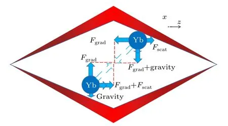
Fig. 9. A schematic diagram of the forces on ytterbium atoms in a bottle beam.
Figure 9 shows the transverse and longitudinal forces on two ytterbium atoms in different positions in the localized hollow beam. It can be seen from the figure that the combined forces(dashed arrows in Fig.9)both point to the center of the hollow region, which leads to the capture of the atoms. The scattering force in the figure is caused by the absorption and re-radiation between the dipole of the beam in the direction of light transmission. The expressions are

wherenis the refractive index of the medium(in this paper,we taken=1.332 for water),ε=8.85×10⁻¹²is the dielectric constant in vacuum, andCis the cross-section of the atomic radiation pressure,which is expressed as
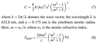
Here,cis the speed of light propagation in a vacuum.
Based on Eqs. (6)–(8), the gradient force and scattering force distributions of the multiple bottle optical field on ytterbium atoms are calculated,as shown in Fig.10.

Fig.10. The gradient force and scattering force distribution of multiple bottle beams. (a)Radial gradient force distribution. (b)Radial scattering force distribution. (c) A comparison of radial gradient force and radial scattering force. (d)Transverse gradient force distribution at 7.45µm and 11.24µm.
Figure 10(a)shows the distribution of the radial gradient force(z-direction): the gradient force is 0 at the black dashed line, and the black solid line marks the range where the bottle beams of 1, 2, 3, and 4 are located. The region where the radial gradient force is greater than 0 means that the direction of the gradient force is in thez-axis positive direction;in contrast, the region where the radial gradient force is less than 0 means that the direction of the gradient force is in thez-axis negative direction. Therefore, it can be seen from the figure that gradient force balance points exist in all four bottle light regions. Figure 10(b)shows the radial scattering force distribution. Figure 10(c)shows the radial gradient force compared with the radial scattering force,where the red line is the radial gradient force,and the black line is the radial scattering force.The scattering force is 5 orders of magnitude smaller than the gradient force,as can be seen from the figure. Therefore, the effect of the scattering force is minimal compared to the gradient force.Figure 10(d)shows the distribution of the transverse gradient force at 7.45µm and 11.24µm(beams 2 and 4).Similarly,a transverse gradient force greater than 0 means that the direction of the gradient force is in the positive direction of thex-axis, and a transverse gradient force less than 0 means that the direction of the gradient force is in the negative direction of thex-axis.It can be seen from the figure that there is a transverse gradient force balance point at the center point(x=0).Gradient force equilibrium points in both transverse and radial light fields imply that the atoms can be imprisoned. Here,the transverse and radial forces are defined as the forces exerted on the particle along thexandzdirections,respectively.
4.2. Feasibility analysis of multiple bottle optical field imprisoned particles
To achieve stable capture of atoms,three stability criteria need to be satisfied.
1. The gradient force needs to be greater than the scattering force. The particle capture mainly relies on the gradient force generated by the optical field. We use the stability factorRto express the ratio of the gradient force and the scattering force,and its expression is

2. Another factor that affects the stability of the beam to enable it to capture particles is the Brownian motion of the particles, which affects the stability of the capture when the size of the particles being manipulated is small. Therefore,to capture the particles stably,the potential well generated by the gradient force should be deep enough to overcome the kinetic energy of the particles. In other words, the kinetic energy of the particle must be much smaller than the potential trapping well,which is expressed as
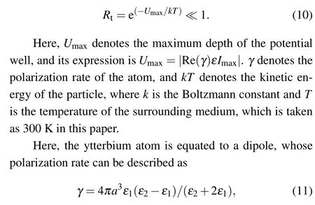
whereε1=1.796 is the dielectric constant of the environment surrounding the atom. Here,ε2=−54+5.9i is the dielectric constant of the ytterbium atom.
3. The gradient force can balance the gravity of the particles. Therefore,the gradient force needs to be larger than the gravity of the particles.
In this paper,the bottle beams of Nos.1 and 3 are selected to calculate their gradient forces and scattering forces. Also,the feasibility of trapping multiple ytterbium atoms is calculated. Since the scattering force is transmitted in the direction of light transmission (radial direction), there is no scattering force distribution in the lateral movement,so the stability criterion of (1) only needs to analyze the force in the radial direction. For bottle beam No. 1, it is calculated that: (1) the stability factorR1=2642.7 yields a radial gradient force four orders of magnitude larger than the radial scattering force;(2)the beam radialRt1=5.74e−22and transverseRt1=1.87e−5,both much smaller than 1,indicate that the potential trap generated by the gradient force is sufficient to overcome the kinetic energy generated by the Brownian motion of the atoms;(3) gravityG=2.82e−24is six orders of magnitude smaller than the gradient force, and gravity can be neglected. Therefore, stable confinement can be achieved for the No. 1 bottle beam.
For the No. 3 bottle beam, it is calculated that: (1)the stability factorR2= 2242.7; (2) the beam radialRt2=4.2147e−28and the beam transverseRt2=5.19e−8; (3)gravityG=2.82e−24.By combining the three stability criteria,the No.3 bottle beam can also achieve stable confinement. Therefore,both Nos.1 and 3 bottle light fields can achieve cooling and captivity of ytterbium atoms, and the capture of multiple particles is achieved.
5. Conclusion
In this paper, the P–B phase metasurface is used to generate several micron-scale bottle beams. Two bottle beams are selected and their transverse full-widths at half-maximum are measured to be 0.46 µm and 0.6 µm, with longitudinal fullwidths at half-maximum of 0.85µm and 1.12µm. The metasurface lens can change the number of bottle beams generated by controlling the size of the annular obstacle. And the shape of the focal point can be changed by changing the rotation of thex-component of the unit,which generates an elliptical bottle beam.
Two of the bottle beams are selected, and their ability to imprison Yb atoms is analyzed. By combining the three stability criteria, it is concluded that both bottle beams can cool and imprison the ytterbium atoms.
In practical applications, the metasurface is lighter, thinner,and easier to integrate. Moreover,the size of the multiple bottle beams generated in this paper is significantly reduced,resulting in more accurate capture of tiny particles. The multiple bottle beams will have applications in super-resolution microscopy,super-resolution lithography,high-density data storage, optical micromanipulation of nanoparticles, and nanooptical manufacturing.
Acknowledgment
Project supported by the State Key Laboratory of Applied Optics(Grant No.SKLA02020001A17).
- Chinese Physics B的其它文章
- Direct measurement of two-qubit phononic entangled states via optomechanical interactions
- Inertial focusing and rotating characteristics of elliptical and rectangular particle pairs in channel flow
- Achieving ultracold Bose–Fermi mixture of 87Rb and 40K with dual dark magnetic-optical-trap
- New experimental measurement of natSe(n,γ)cross section between 1 eV to 1 keV at the CSNS Back-n facility
- Oscillation properties of matter–wave bright solitons in harmonic potentials
- Synchronously scrambled diffuse image encryption method based on a new cosine chaotic map

