Numerical investigation of a muzzle multiphase flow field using two underwater launch methods
Jing-hui Zhang,Yong-gang Yu,Xin-wei Zhang
School of Energy and Power Engineering,Nanjing University of Science & Technology,Nanjing,210094,China
Keywords:Underwater launch Multiphase flow Muzzle flow field Numerical simulation Mach disk
ABSTRACT A two-dimensional axisymmetric model,employing a dynamic mesh and user-defined functions,is used to numerically simulate the transient multiphase flow field produced by an underwater gun.Furthermore,a visualized shooting experiment platform with a high-speed camera is built to observe the evolution process of such a multiphase flow field.The simulated phase distribution diagram is agreed well with the shadow photo of the experiment,indicating that the numerical model is reasonable.Further examinations of the multiphase flow fields by using the submerged and sealed launch methods show that use of the sealed launch can significantly improve the interior ballistic performance of an underwater gun.In the cases by using these two types of underwater launch methods,the displacement of the projectile within the range of the muzzle flow field meets the exponential law over time.Moreover,a not fully developed bottle-shaped shock wave is formed when t=0.4 ms,but this bottle-shaped shock wave expands more rapidly for the sealed launch.In addition,the amplitude of pressure oscillation for the sealed launch is larger than that of the submerged launch,but the pressure oscillation of the sealed launch lasts shorter.
1.Introduction
The muzzle flow field generally refers to the time-varying region of gas flow formed by its expansion outside the muzzle once a gun has been fired,where this is an unsteady and complex flow field with abrupt shock waves[1].Initially,experimental methods were mainly used to study the muzzle flow field.For example,Schmidt et al.[2] experimentally observed the influence of the precursor flow field and found that the interactions between the precursor and propellant gas flow fields significantly influence the near muzzle flow.Klingenberg [3] experimentally measured the parameters of the gas in the muzzle flow field,and the results showed that the turbulence of the muzzle flow field hinders the development of the inner slip surfaces which prevents the influx of oxygen from the outer atmosphere.The muzzle flow field is a transient process with a very short duration,which makes it difficult to measure its parameters in the experiment.With the development of computational fluid dynamics (CFD),an increasing number of researchers use numerical methods to study the muzzle flow field,for example:Jiang et al.[4,5]carried out numerical studies on wave dynamic processes occurring in muzzle blast flows,which are created by a supersonic projectile.The results indicated that a higher pressure ratio dramatically increases the acceleration of the projectile while the effect of the pressure ratio is mainly limited by the muzzle near field.Li and Hao [6] carried out numerical simulations to analyze the effects of different muzzle velocities and found that a shear layer is formed at the warhead and extends outward both in the supersonic and hypersonic flow fields.Ye et al.[7]applied numerical methods to study the influence of the shape of the projectile nose on the muzzle flow field and found that the velocity variations caused by the shape of the projectile nose are negligible as the duration time is very short.Zhuo et al.[8] used a kinetic model to solve the Euler equations of chemical nonequilibrium and numerically simulated the launch process of a base bleed projectile from the muzzle to the free-flight stage.Gao et al.[9]established a hydrodynamic model for the dynamic simulation of the railgun muzzle flow field.By analyzing the aerodynamic simulation results,they found the muzzle arc has negative impacts on the muzzle environment and the bore interior,which are mainly caused by the complicated muzzle flow field and the rise of temperature.
Underwater guns are suitable for the short-range defense of offshore ships because they have a short response time,and are highly reliable.However,water that has a density about 800 times higher than that of air is an incompressible fluid in most cases,which results in that the performance of the underwater launch is different from that in air.On the one hand,there is considerable resistance when a gun is launched underwater.On the other hand,a large amount of high-temperature gas is injected into water,causing drastic gas-water mixing.In addition,affected by the highdensity water,the structure of the complex shock wave in the muzzle flow field is difficult to predict,where this poses a daunting challenge to the use of guns for underwater launches.
An underwater launch is accompanied by the interaction between a gas jet and water.By focusing on gas-liquid interaction during the underwater lunch,Hu [10] and Zhao [11,12] designed nozzles with different shapes to study of the expansion characteristics of a gas jet in a liquid-filled tube,and their research revealed the energy transfer rule and the evolution law of the multiphase flow field.Moreover,based on previous research,a new submerged gun launcher was proposed by Zhou [13-15],which achieved a low-resistance launch by guiding the gunpowder gas to the front of the projectile.Shi et al.[16] conducted a series of experiments on underwater supersonic gas jets,and found that supersonic gas jets are always accompanied by strong flow oscillations when sprayed in water.
The submerged launch and the sealed launch are two major launch methods for the underwater guns.The submerged launch is the one that the gun barrel is directly submerged in water,as shown in Fig.1(a).In this case,the barrel is filled with water during the interior ballistic process,and thus the launch resistance is high,which increases the chamber pressure and reduces the muzzle velocity.By contrast,the sealed launch is a low-resistance launch method,in which a diaphragm is used to seal the muzzle to separate the barrel from the water before launch,as shown in Fig.1(b).Such a low-resistance launch can reduce the launch resistance and increases the muzzle velocity.To analyze the flow field formed by a sealed underwater gun,a series of numerical simulations were carried out by Zhang and Yu [17],and they found that the sealed launch and the air launch have similar interior ballistic performance.
Most previous studies have focused on the muzzle flow field in the air,and the interaction between the gas jet and water.A few studies have been conducted on the muzzle flow field of a sealed underwater gun.In our previous research [18],preliminary numerical simulations of the muzzle flow field for the submerged launch were carried out,but we have not compared the submerged lacunch with other launch methods such as the in-air launch and the sealed launch.Besides,the evolution of the bottle-shaped shock wave which is an important phenomenon in the muzzle flow field of the underwater gun has not been quantitatively analyzed in previous works.Therefore,in this paper,the muzzle flow fields of the underwater gun with the submerged launch and the sealed launch have been investigated by experiments and numerical simulations,respectively.In addition,the impacts of different underwater launch methods on the expansions of bottle-shaped shock waves are quantitatively studied by some physical parameters such as the Mach disk diameter and the Mach disk displacement.The results are important for understanding the characteristics of the underwater multiphase flow field and for reducing the harmful effects of the gas jet and provide a reference for the design of new underwater guns.
2.Numerical model and calculation method
2.1.Physical model
Based on the characteristics of an underwater gun,the following assumptions are made:
(1) The combustion of the propellant follows the law of geometrical combustion.The propellant particles are burned under the mean pressure and follow the law of exponential burning rate.The heat and temperature generated by the combustion of unit mass propellant are constant.The gas composition does not change during the expansion.
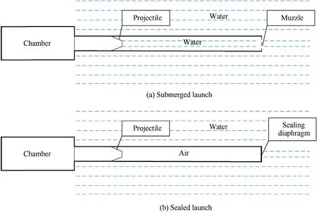
Fig.1.Schematic diagram of two types of underwater launch methods.
(2) The impetus f,covolume β,and specific heat ratio kare constant.Among them,the impetus fis work done by the expansion of the gas produced by the combustion of 1 kg propellant at an atmospheric pressure when the temperature rises from 0 to T,covolume β is the volume of 1 kg propellant gas molecules,and kis the index of the reversible adiabatic process of the ideal gas.
(3) The energy produced by the combustion of propellant not only provides kinetic energy for the projectile,but also loses part of the energy due to friction and heat dissipation,which is called the secondary work.Among them,the heat dissipation on the inner surface of the barrel is indirectly corrected by reducing for increasing k,while other factors are considered by introducing the secondary work coefficient φ.
(4) According to previous experiment results [18],gravity has little influence on the underwater muzzle flow field during a short time,and the flow field can be considered to be twodimensional (2D).Therefore,a 2D axisymmetric model is used in this work.
(5) The gas jet is assumed as the ideal gas and the gas body force is ignored.
(6) Water is assumed to be incompressible,with a density of 998.2 kg m.The vaporization of water caused by the hightemperature gas is ignored because the gas flow interacts with water for only a short period,while the cavitation caused by the projectile is considered.
(7) In the trial calculation,it is found that the Mach number of the vapor generation area is lower than 0.2,so water vapor is assumed to be incompressible,with a density of 0.5542 kg m.
2.2.Mathematical model
(1) Mass conservation equation:

where subscript q is selected from 1 to 3 to represent the gas,liquid,and vapor phase,respectively;ρrepresents the density of the q phase.αrepresents the volume fraction of the q phase,and α+α+α=1.t represents the time.Uis the velocity vector of the q phase.Sis the source term of mass transfer between vapor and liquid,and it is 0 when no mass transfer between these two phases.
(2) Momentum conservation equation:

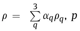
(3) Energy conservation equation:


where;E is the average energy;T is the average temperature;kis the effective thermal conductivity;Sis the source term of energy which indicates the energy change caused by the cavitation.
(4) State equation:

where R=319.6 J/(kg∙K),which is the constant of propellant gas,ρ=998.2 kg m.
(5) Turbulence equation:
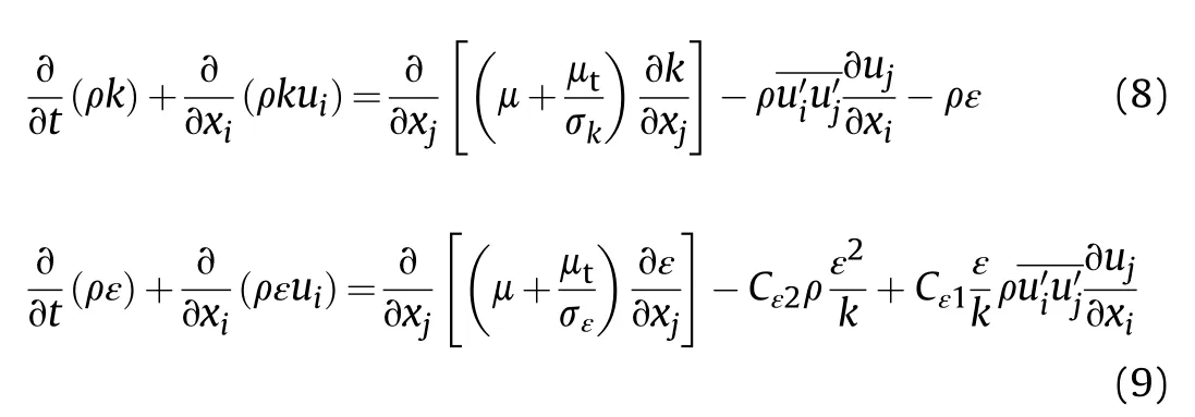
The standard k-ε turbulence model is a semi-empirical formula containing two variables that the turbulent kinetic energy k and its diffusivity ε.The transport equations are:

(6) Schnerr-Sauer cavitation model
In this work,the volume of fluid (VOF)method is used to track and locate the gas-liquid interface,and the Schnerr-Sauer model is applied for the cavitation simulation.The VOF model coupled with the Schnerr-Sauer model has been verified capable of obtaining convincing results in the simulations of the underwater supercavitating projectiles [19,20].The underwater muzzle flow field in this work has similar physical phenomena to that of the literature[19,20],such as the process of the projectile exiting the muzzle and then entering the water.Therefore,the Schnerr-Sauer cavitation model also can be used to describe the natural cavitation caused by the high-speed projectile in this paper.
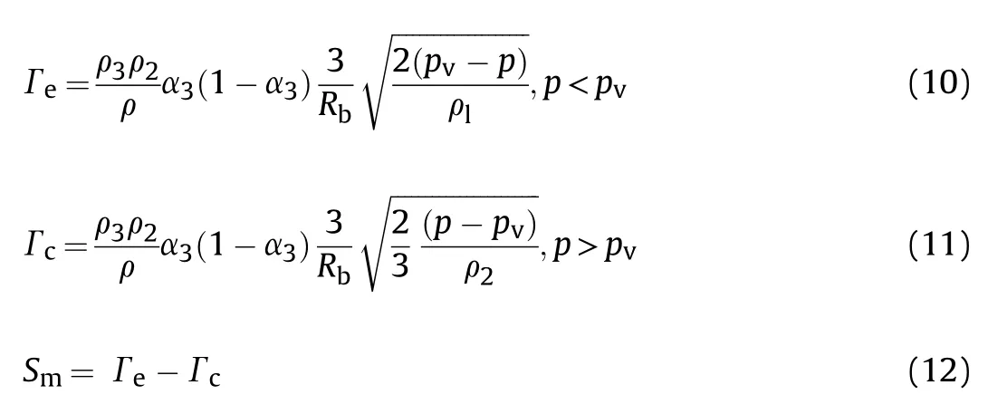

where Ris the radius of the bubble,which can be expressed as:

Γand Γrepresent the mass transfer source term when the bubble grows and collapses respectively;pis the saturated vapor pressure and p=3540 Pa;c is the number of bubbles per unit volume,and c=10normally in the Schnerr -Sauer cavitation model [21];Lis the latent heat of vaporization.
It is necessary to couple the interior ballistic equations for calculating the muzzle flow field.The interior ballistic equations are as follows:
(1) Form function of the propellant:

where ψ is the mass fraction of the burnt propellant,Z=e/eis the relative thickness of the burning propellant,eis the half of the web-thickness of the propellant,and e is the burnt thickness.Zis the relative thickness of the burnt propellant when the particles are burnt out.χ,λ,and μare the form quantities of the burnt propellant,which are only related to the shape and size of the propellant.χand λare the form quantities when the propellant surface starts to decrease.
(2) Law of the propellant burning:

where uis the burning coefficient,n is the burning exponent.
(3) Momentum equation of projectile:

where Ais the sectional area of the projectile,pis the pressure at the projectile bottom,pis the pressure at the warhead,m is the projectile mass,v is the projectile velocity,and φ is the secondary work coefficient.
(4) Interior ballistics energy equation:

where lψ is the diameter of the free volume in the chamber,l is the projectile displacement,θ=k-1 is the adiabatic exponent.fand ω are the impetus and the charge weight,respectively.lis the length of the barrel,lis the diameter shrunk length of the chamber,and Δ is the loading density.
(5) Motion equation:

Eqs.(16)-(21) jointly form interior ballistic equations.
2.3.Calculation method
The underwater launch process is simulated by using the Computational Fluid Dynamics(CFD)software with the VOF model and the Schnerr-Sauer cavitation model.In the computational model,the PRESTO! method is used for the discretization of the pressure gradient term;the first-order upwind method is used to dispersing momentum and energy,while the second-order upwind method is employed in the turbulence and density equations.The pressure implicit splitting operator (PISO) algorithm is used to couple the pressure and velocity.In order to balance the calculation efficiency and accuracy,the time step is set to 1 × 10s.
User-defined function(UDF)is a user-made program,which can be dynamically connected to a fluent solver to improve the performance of the solver.In this paper,since the CFD software can not directly calculate the interior ballistic process,the interior ballistic Eqs.16-21 are written in the UDF file.In the calculation process,at first,the governing Eqs.1-15 can be solved to get the warhead pressure pand then transferring pto the interior ballistic equations in the UDF.The projectile velocity v can be obtained by solving the interior ballistic equations,and then is fed back to the dynamic mesh to achieve the movement of the projectile.
3.Grid division and convergence verification
3.1.Grid division
The calculation domain for simulation (as shown in Fig.2) can be divided into the barrel area and the flow field area.The barrel area is cylindrical with a length of 1 m and a radius of 6.35 mm,and the flow field area is cylindrical with a length of 1 m and a radius of 0.3 m.Most grids in the entire calculation domain are structured,and the grids around the muzzle are encrypted with a grid size of 0.3 mm × 0.3 mm.The layering method of the dynamic mesh technique is applied to achieve the movement of the projectile.As the projectile moves forward,the grid near the projectile bottom will be stretched and split into two grids when its length his extended from 0.3 mm to 0.6 mm.Similarly,the grid near the warhead will be merged with another grid when its length his compressed to 0.2 mm,which can be seen in Fig.3.
The boundary conditions of the calculation domain are set as follows: the wall of the chamber is defined as the pressure inlet,and the chamber pressure can be obtained by solving the interior ballistic equations;the outer boundary of the flow field area is defined as the pressure outlet with the environmental pressure(101,325 Pa).For the submerged launch,the barrel area in front of the projectile is initialized to be full of water.On the other hand,for the sealed launch,the barrel area is initialized to be full of air.The temperature and pressure are initialized according to the environmental conditions,namely,300 K and 101,325 Pa,respectively.
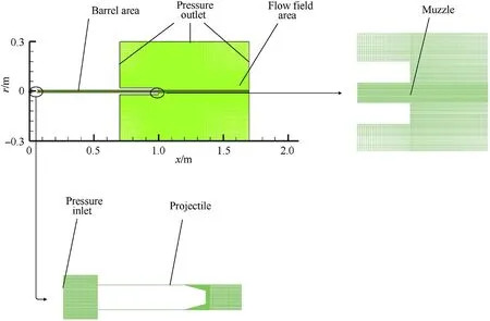
Fig.2.Schematic diagram of the calculation domain,grids and boundary conditions.

Fig.3.Schematic diagram of the layering method.
3.2.Grid convergence verification
To eliminate the influence of the grid thickness on the simulated results,we use calculation grids with grid number N=200000,150000,120000 and 100000 for trial calculations.As can be seen in Fig.4,the axial pressure has complex fluctuations after several expansion-compression processes,which indicates there are complex waves in the flow field.The axial pressure curves can effectively reflect the position and amplitude of shock waves,and thus we choose them when t=1.0 ms as the characteristic parameters for the verification of grid convergence.
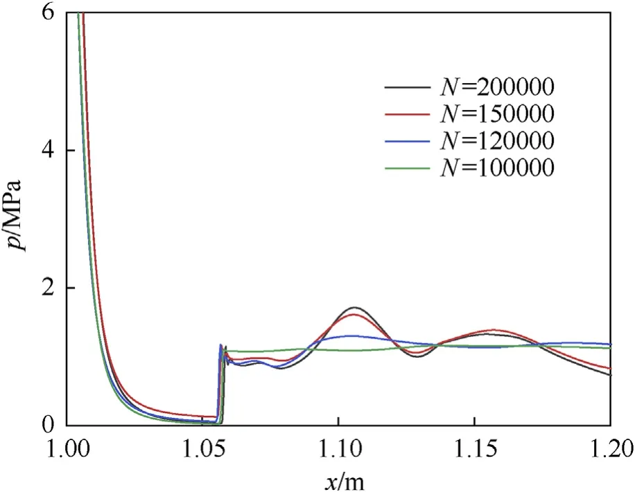
Fig.4.Curve of axial pressure (t=1 ms).
The pressures all drop rapidly at first,and then rise sharply at a Mach disk near x=1.06 m for the four grids,as shown in Fig.4.Moreover,the peak pressures at this Mach disk are close for the four grids,which indicates that the grid number in the range of 100000 to 200000 has little effect on capturing shock waves with a larger amplitude.On the other hand,the grid can hardly capture the pressure oscillation behind the Mach disk for N=100000.Moreover,the grid can capture some pressure oscillations,but their amplitude is small for N=120000.In the case that the grid number increases to N=150000 and N=200000,the waveforms of the two pressure curves are almost identical,and these curves both have two more obvious pressure oscillations after the Mach disk.In addition,the maximum relative error of the pressure for N=100000,N=120000 and N=150000 is 29.6%,23.5% and 3.7% compared with that of N=200000,respectively,which indicates that the grid can accurately capture pressure oscillations with smaller amplitude for N ≥150000.Therefore,considering both the efficiency and accuracy of the calculation,we choose the grid with N=150000 to for calculation.
4.Model verification
In this paper,a numerical model for the underwater launch is established,and numerical simulations are carried out for the submerged launch and the sealed launch.The projectile used in the numerical simulation weighs 45 g,and the charge mass of the 4/7 single-base propellant is 4 g.To verify the numerical model and further investigate the muzzle multi-phase flow field of underwater launch,a visual experimental system is constructed,and the schematic diagram is shown in Fig.5.This experimental system consists of five parts that are water tank,launcher platform,pulse ignition source,high-speed camera system,and pressure measuring system.The water tank is 1.0 m in length,0.4 m in width,and 0.6 m in height.There is a window on the front of the water tank for observation and a shooting hole in the center of the side wall for the barrel to penetrate.The deceleration buffer box is filled with sand to collect the bullets.The launcher platform subsystem has a 12.7 mm gun that is fixed under the cement platform.The pressure of the combustion chamber is measured by the piezoelectric pressure sensor and the piezoelectric signal generated by the sensor is amplified by the charge amplifier and then is recorded by the computer.The pulse ignition source is connected to the chamber to ignite the propellant.A FASTCAM-Ultima APX highspeed camera is applied to record the evolution of the flow field with the resolution of 1024×512 pixels,and the frequency of 4000 frames per second.To ensure a submerged environment during the submerged launch,the barrel and water tank are filled with water.For the sealed launch,a diaphragm is used to seal the muzzle to ensure that the chamber is filled with air.After all the devices have been ready,the charge is ignited by the pulsed electric igniter,and the high-speed camera is used to observe the evolution of the multiphase flow field.
The experiments of the underwater muzzle flow field also apply the 45 g projectile and 4 g 4/7 single-base propellant for the comparison,and the results are as follows:the muzzle velocities of the projectile in the experiment for the submerged launch and the sealed launches are 303.90 ± 0.35 m/s and 233.1 ± 0.34 m/s,respectively,which are consist with the numerical valves.Moreover,the comparisons between the experimental shadow photographs and the simulated phase diagrams are shown in Fig.6 and Fig.7.
The moment when the projectile is leaving the muzzle is defined as t=0.As can be seen from Fig.6(a),during the submerged launch,the projectile continuously pushes the water column in the barrel like a piston after ignition.Since the water is incompressible,the projectile accelerates continuously,causing the local pressure at the muzzle to decrease.When the pressure drops below the saturated vapor pressure of the water (3540 Pa),the cavitation occurs near the muzzle,producing a mass of water vapor.In Fig.6(b),as the projectile emerges from the muzzle,the gas from the burning gunpowder in the chamber begins to leak out from the muzzle and mixes with the water vapor,initially forming a Taylor cavity.During the collision between the gas and the gas-liquid interface,the strong shearing effect causes the rapid mixing of gas and liquid.The boundary of the cavity becomes irregular under the effect of Kelvin-Helmholtz instability.At the same time,as the pressure near the muzzle is increased caused by the gas from the propellant,the water vapor mass quickly collapses.As the projectile passes through and out of the Taylor cavity with a higher velocity relative to the water medium,the natural cavitation initially occurs on the side surface of the projectile.Meanwhile,the projectile drives the flow of the surrounding water medium and provides space for the axial expansion of the Taylor cavity,and thus the Taylor cavity has a significant expansion in the axial direction.However,the Taylor cavity is still blocked by the high-density water medium in the radial direction,and thus its radial expansion is small,causing the head of the cavity to become tapered,as shown in Fig.6(c).In Fig.6(d),as the projectile continues to move forward,the length of the cavitation on the projectile surface gradually increases,and then the projectile is enveloped by the vapor after the formation of supercavitation.A slender air column is left at the tail of the projectile and is connected to the Taylor cavity.However,the Taylor cavity slowly expands in the axial and radial directions with a tapered head owing to the continuous ejection of the subsequent gas.

Fig.5.Schematic of the experimental setup.
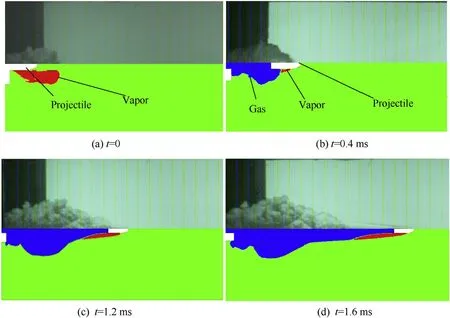
Fig.6.Comparison of shadow photographs (upper parts) and simulated phase diagrams (lower parts) during the submerged launch.
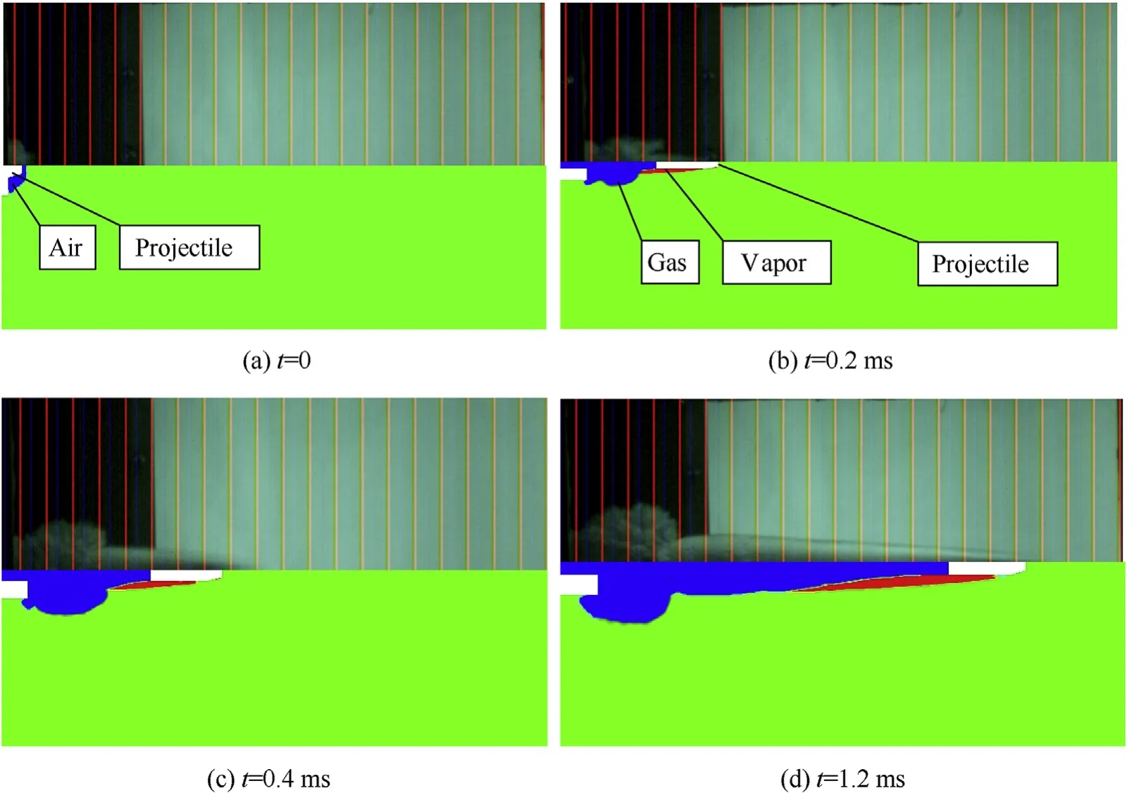
Fig.7.Comparison of shadow photographs (upper parts) and simulated phase diagrams (lower parts) during the sealed launch.
For the sealed launch,unlike the submerged launch,the barrel remains filled with air.As can be seen from Fig.7,after ignition,the air column is continuously pushed and compressed by the projectile and is simultaneously blocked by the high-density water medium,which leads to the accumulation of the air column in the muzzle.At this moment,the gas-liquid interface protrudes only slightly from the muzzle without any significant change in the flow velocity and any cavitation in the muzzle,as can be seen in Fig.7(a).In Fig.7(b),the projectile quickly passes through the gas and contacts with water directly after leaving the muzzle,leading to the natural cavitation at the surface of the projectile.In Fig.7(c)and(d),a Taylor cavity is formed as the gas is ejected continuously from the muzzle.The projectile passes through the Taylor cavity very quickly,which causes the axial resistance of the projectile has no significant decrease.Therefore,the axial displacement of the Taylor cavity is much smaller than that in the case of the submerged launch,is it why the shape of the Taylor cavity is spherical in the case of the sealed launch.As the projectile continues to fly forward while leaving a slender air column,the Taylor cavity expands slowly in both axial and radial directions.
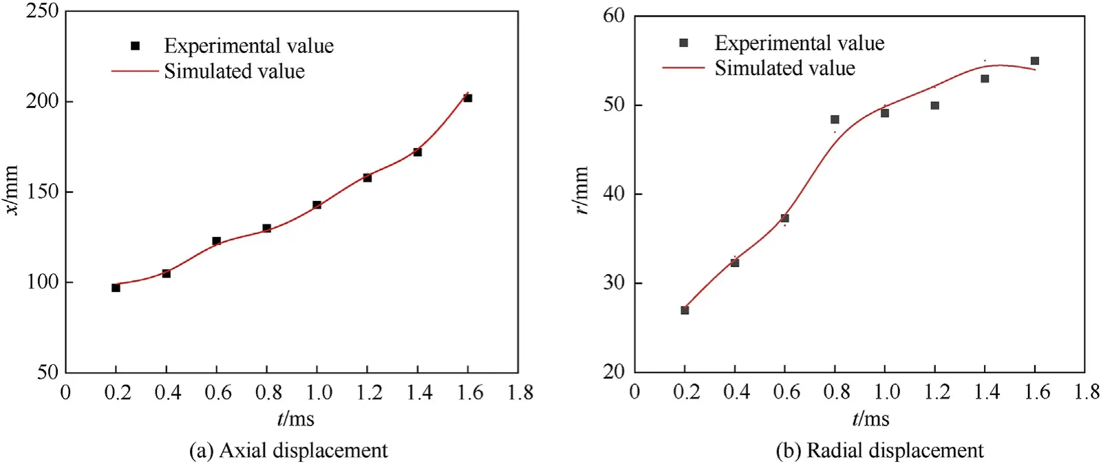
Fig.8.Displacement of the Taylor cavity during the submerged launch.
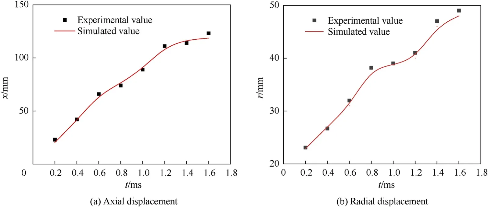
Fig.9.Displacement of the Taylor cavity during the sealed launch.
Figs.6 and 7 show that the external contours of the muzzle multiphase flow field in the experimental shadow photographs are consistent with those in the numerical simulation phase diagrams.Moreover,Figs.8 and 9 show that the maximum displacements of the numerical results are in good agreement with the values measured in the experiments,and the average relative error is 2.3% and 3.3% for the submerged launch and the sealed launch,respectively,indicating that the numerical model in this paper is reasonable.
5.Characteristics of muzzle flow field
To study the influence of the launch method on the muzzle flow field,numerical simulations and comparative analysis of the muzzle flow field of a 12.7 mm ballistic gun are carried out for both submerged and sealed launches.
The initial parameters of the muzzle as calculated from the internal ballistic equations are shown in Table 1,where vis themuzzle velocity which is the projectile velocity when t=0 and Pis the pressure at muzzle when t=0.Figs.10-12 show curves of the chamber pressure,projectile displacement,and projectile velocity respectively.

Table 1.Initial parameters of the muzzle.
Figs.10 and 12 shows that the maximum chamber pressure in the case of the sealed launch is equal to 38% of that for the case of the submerged launch,whereas the muzzle velocity of the projectile is 130% of that for the submerged launch,which shows that the sealed launch method can significantly improve the interior ballistic performance of an underwater gun.It can be seen from Figs.11 and 12 that,during the sealed launch,the projectile directly contacts with water sooner since there is no cavitation at the muzzle,as a consequence of which there is a more rapid decrease in its velocity near the muzzle.In the case of the submerged launch,some of the high-density water medium is expelled by the vapor generated at the muzzle,causing the projectile velocity to slowly decrease after the projectile leaves the muzzle.A fit of the time variation of the projectile displacement outside the muzzle shows that the displacement within the range of the muzzle flow field in both these two launch methods has an exponential dependence on time,namely x=x-xe,where xis the projectile displacement(unit is m),t is time (unit is ms),xis the displacement correction term,xis the deceleration coefficient,and tis the time growth factor.The parameters of the fitting relationship are shown in Table 2.
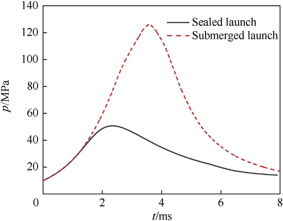
Fig.10.Chamber pressure.
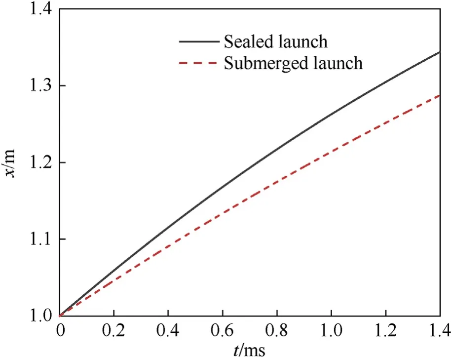
Fig.11.Displacement of the projectile.

Table 2.Fitting parameters for the time dependence of the projectile displacement.
The high-temperature and high-pressure gas expands rapidly and forms a complex wave structure after being ejected from the chamber.To determine the influence of the launch method on the evolution of the muzzle flow field,Figs.13 and 14 show Mach number cloud and contour maps for these two launch methods,respectively.To facilitate a comparison and analysis of the muzzle flow field for different launch methods,Fig.15 shows schematic diagrams of the underwater muzzle flow fields during submerged launch,sealed launch,and air launch [1].
The cloud map of Mach number can clearly show the velocity distribution in the flow field,while the schlieren map can clearly show the shock waves.It can be seen from Figs.13 and 14 that the structures of shock waves present a similar evolutionary law during t=0.2-0.4 ms for these two types of underwater launch methods.When t=0.2 ms,the expansion waves are reflected both at the gasliquid interface and the projectile bottom due to the rapid expansion of the gas jet,and then such waves are converged into a bowshaped shock wave near the muzzle.Subsequently,when t=0.4 ms,with the further expansion of the Taylor cavity,more expansion waves are reflected and converged into two incident oblique shock waves.After that,these two shock waves intersect irregularly,forming a Mach disk and two reflected shock waves.The junction of the incident oblique shock wave and the Mach disk is called the three-wave point.These waves evolve into a bottleshaped shock wave and split the muzzle flow field into the following five regions (as shown in Fig.15):
· Region 1 is the free-expansion zone in the bottle-shaped shock waves.The gas jet mainly expands in this bottle area,with a sharp drop in pressure and a sharp increase in velocity.
· Region 2 is the supersonic zone between the intersecting shock waves and the jet boundary
· Region 3 is the subsonic zone downstream of the Mach disk with a sharp drop in velocity and a sharp increase in pressure and temperature
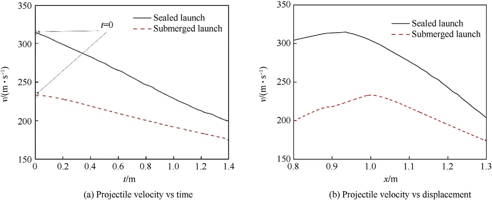
Fig.12.Projectile velocity curves.
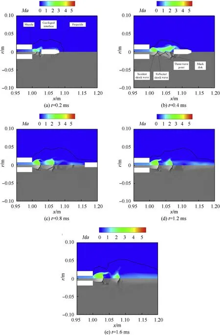
Fig.13.Cloud maps of Mach number (upper part) and schlieren map for the submerged launch.
· Region 4 is the supersonic zone where the gas jet flow becomes complicated after two oblique shock waves
· Region 5 is the transition zone of turbulence.
Ref.[1]shows the typical structure of bottle-shaped wave for an air launch,as shown in Fig.15(c).Because water has greater density and viscosity than air,the underwater bottle-shaped shock waves have some differences compared with the shock waves in air.The shape of Region (1) (free expansion zone) is not fully developed because this region is compressed by water in the radial direction;the incident oblique shock waves shrink inward radially,and the diameter of the Mach disk becomes small.
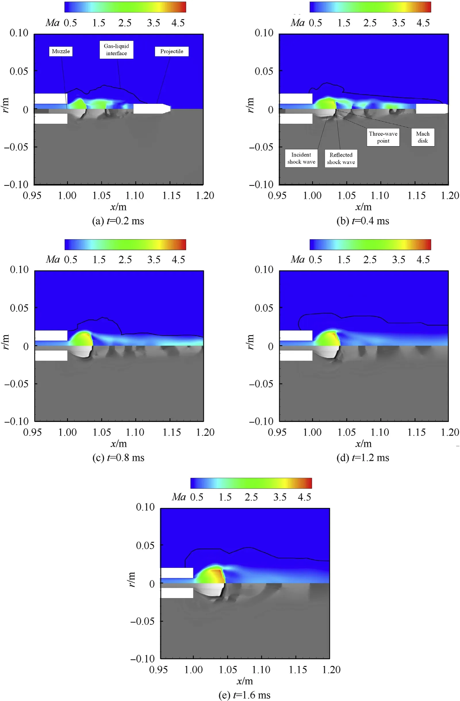
Fig.14.Cloud maps of Mach number (upper part) and schlieren map for the sealed launch.
The initial bottle-shaped shock waves when t=0.4 ms for different launch methods have similar characteristics,but launch methods can significantly affect the subsequent development of shock waves.To analyze the influence of muzzle velocity on shock waves,the diameter of the Mach disk is defined as the distance between two three-wave points,and the displacement of the Mach disk is the distance from the Mach disk center to the muzzle.Fig.16 and Fig.17 show the diameter and the displacement of the Mach disk for the sealed launch and the submerged launch.The diameter of the Mach disk can effectively reflect the radial expansion of the bottle-shaped shock wave,while the displacement of the Mach disk can reflect the radial expansion of the bottle-shaped shock wave.
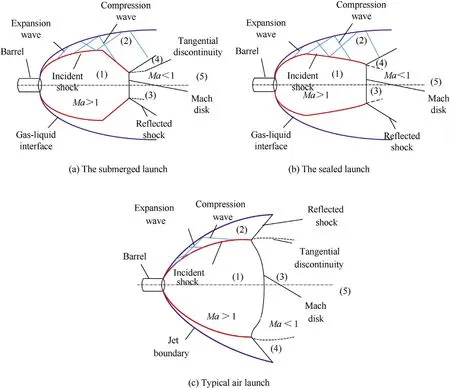
Fig.15.Schematic diagrams of the muzzle flow field flow for different launch methods.
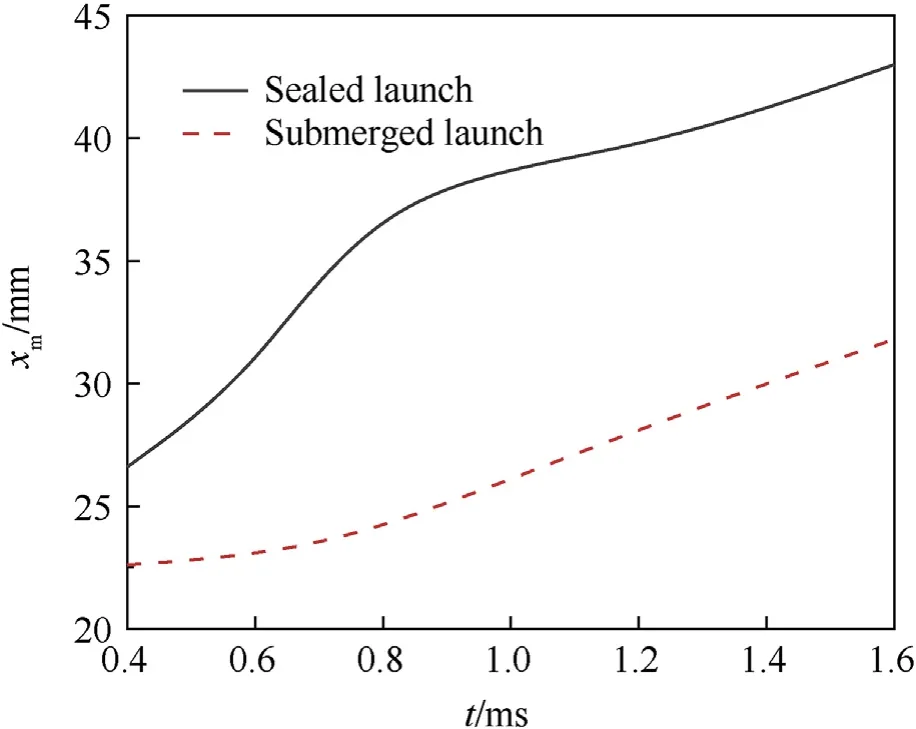
Fig.16.Displacement of Mach disk vs time.
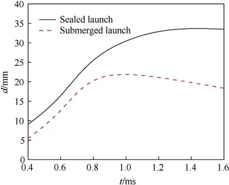
Fig.17.Diameter of Mach disk vs time.
As can be seen from Figs.16 and 17,for different launch methods,the volume of the Taylor cavity is increased with the continuous gas ejection after t=0.4 ms,which provides more space for the expansion of bottle-shaped shock waves.As the incident oblique shock wave deflects outward,the diameter of the Mach disk is increased gradually,and the bottle-shaped shock wave expands gradually in both axial and radial directions.Although the expansion laws of the bottle-shaped shock waves for the sealed launch and the submerged launch are similar to each other,the launch method also can affect the propagation velocity of the bottle-shaped shock wave.For the sealed launch,the displacement and the diameter of the Mach disk are both increased rapidly with time during t=0.4-1.6 ms,in which the displacement of Mach disk is increased from 26.6 mm to 43.1 mm,and the Mach disk diameter is increased from 9.1 mm to 33.5 mm.On the other hand,for the submerged launch,the Mach disk displacement is increased slowly with time from 5.4 mm to 18.3 mm during t=0.4-1.6 ms.The diameter of Mach disk is increased from 5.4 mm to 23.0 mm during t=0.4-0.8 ms and then decreased slowly to 18.3 mm during 0.8-1.6 ms.When t=0.4 ms,the diameter and displacement of the Mach disk for the submerged launch are 60.0% and 84.9% of that for the sealed launch,respectively.At t=1.6 ms,the diameter and displacement of the Mach disk are 54.6% and 73.0% of that for the sealed launch,respectively.In other words,the diameter and displacement of the Mach disk for the submerged launch is increased more slowly than that of the sealed launch,indicating that the bottle-shaped shock wave for the sealed launch expands more rapidly.For the sealed launch,the projectile can leave the muzzle area with a higher velocity due to the less resistance before the projectile,and thus there is more space for the axial expansion of the bottle-shaped shock wave.In addition,the muzzle injection pressure is larger in this case,which makes the bottle-shaped shock wave expand more fully in both axial and radial directions.On the other hand,for the submerged launch,due to a lower muzzle velocity,there is larger resistance on the downstream expansion of the Mach disk.Moreover,the muzzle injection pressure is lower,resulting in that the bottle-shaped shock wave extends slowly in both axial and radial directions.
The evolutions of shock waves in the muzzle flow field which may significantly affect the distribution of pressure and the surrounding environment have been analyzed in the previous analysis.In this section,the influences of two types of launch methods on the pressure distribution are discussed by analyzing the pressure cloud maps (Fig.18 for the submerged launch and Fig.19 for the sealed launch) and the pressure distribution curves along the axis and the radial curve as x=1.02 m (Fig.20).
It can be seen from Figs.18 and 19 that there are some similar behaviors of the pressure distributions in the muzzle flow field for the two launch methods.The bottle-shaped shock waves that appeared at 0.4 ms affect the distributions of the temperature and the pressure.After the gas injecting from the muzzle,the gas pressure drops rapidly in Region(1)(the free expansion zone)and then rises sharply in Region (3) (the subsonic zone) after passing through the Mach disk due to the strong compression effect.In Region (4) (the turbulent mixing zone),there is the pressure oscillation caused by the jet expansion and the compression from the projectile bottom and water,which leads to the alteration structure of the high pressure and the low pressure.Meanwhile.the pressure in the flow field is decreased over time,and these oscillations become weaken over time.
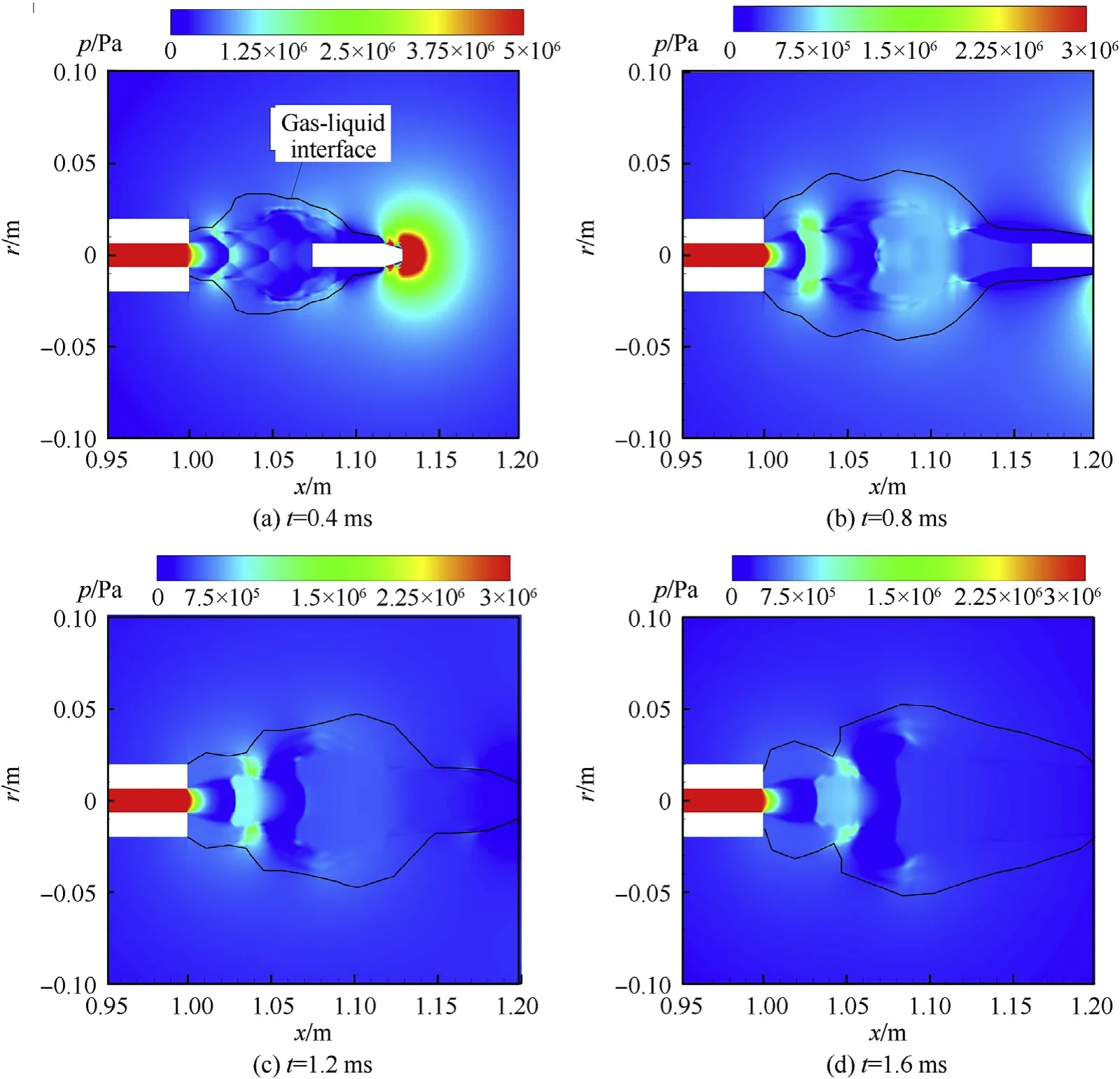
Fig.18.Pressure cloud maps for the submerged launch.
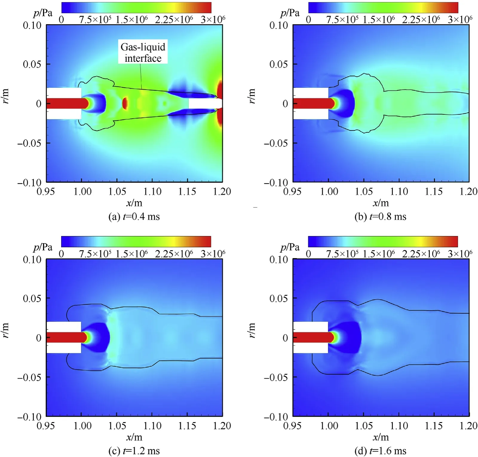
Fig.19.Pressure cloud maps for the sleaed launch.
The pressures in the muzzle flow fields have similar spatial and temporal distributions for the submerged launch and the sealed launch,but the launch method still has a significant impact on the amplitude and duration of pressure oscillations.The maximum pressure difference between the adjacent peak and trough behind the Mach disk can effectively indicate the pressure oscillation amplitude,and such a maximum pressure difference is defined as Δp.As can be seen from Fig.18(a),for the submerged launch,after the gas is ejected from the muzzle,the gas pressure is decreased rapidly along the axial direction and then suddenly rises to about 1.6 MPa at the Mach disk.There are two troughs and one peak of the pressure distribution downstream of the Mach disk,and Δp=0.5 MPa in this case.When t=0.8 ms,the pressure at the Mach disk is decreased to 1.2 MPa,while two peaks and two troughs appear downstream of the Mach disk with Δp=0.4 MPa,indicating that the compression from the projectile and the water medium is strong at this moment,and there are still obvious pressure oscillations.During the period of 1.2-1.6 ms,the pressure at Mach disk is further reduced from 0.8 MPa to 0.6 MPa,while the number and the amplitude of pressure oscillations downstream of the Mach disk are both decreased,namely there is only one pressure oscillation with Δp=0.3 MPa.
It can be seen from Fig.20(b)that the pressure at the Mach disk for the sealed launch is 2.8 MPa at t=0.4 ms,which is 175% of that for the submerged launch at this moment.In addition,there are two large pressure oscillations downstream of the Mach disk for the sealed launch with Δp=1.6 MPa,which is 320% of that for the submerged launch.When t=0.8 ms,the pressure at the Mach disk drops sharply to 1.5 MPa,and multiple pressure oscillations appear downstream of the Mach disk,but the amplitude of pressure oscillation is decreased greatly with Δp=0.6 MPa.
During the period of 1.2-1.6 ms,the pressure at Mach disk is decreased from 1.1 MPa to 0.7 MPa,and there is no obvious pressure oscillation downstream of the Mach disk.Overall,it can be found that the pressure of the Mach disk for the sealed launch is higher than that of the submerged launch;however,the pressure is decreased more rapidly,and the pressure for the sealed launch is only 0.1 MPa higher than that of the submerged launch at t=1.6 ms.Similarly,at t=0.4 ms,the amplitude of pressure oscillations downstream of the Mach disk for the sealed launch is much larger than that for the submerged launch,but the oscillation decreases rapidly,and there is no obvious pressure oscillation at t=1.2 ms for the case of the sealed launch.
The radial pressure distributions for the two underwater launch methods have similar laws to that of the axial pressure distribution.The pressure suddenly rises at the incident oblique shock wave and then is decreased along the radial direction after several oscillations.The pressure at the oblique shock wave is decreased from 1.3 MPa to 0.3 MPa for the submerged launch,while it is decreased from 1.8 MPa to 0.4 MPa for the sealed launch.The pressure oscillation downstream of the oblique shock wave is significantly weakened after t=0.8 ms,and the amplitude is less than 0.1 MPa at this moment.
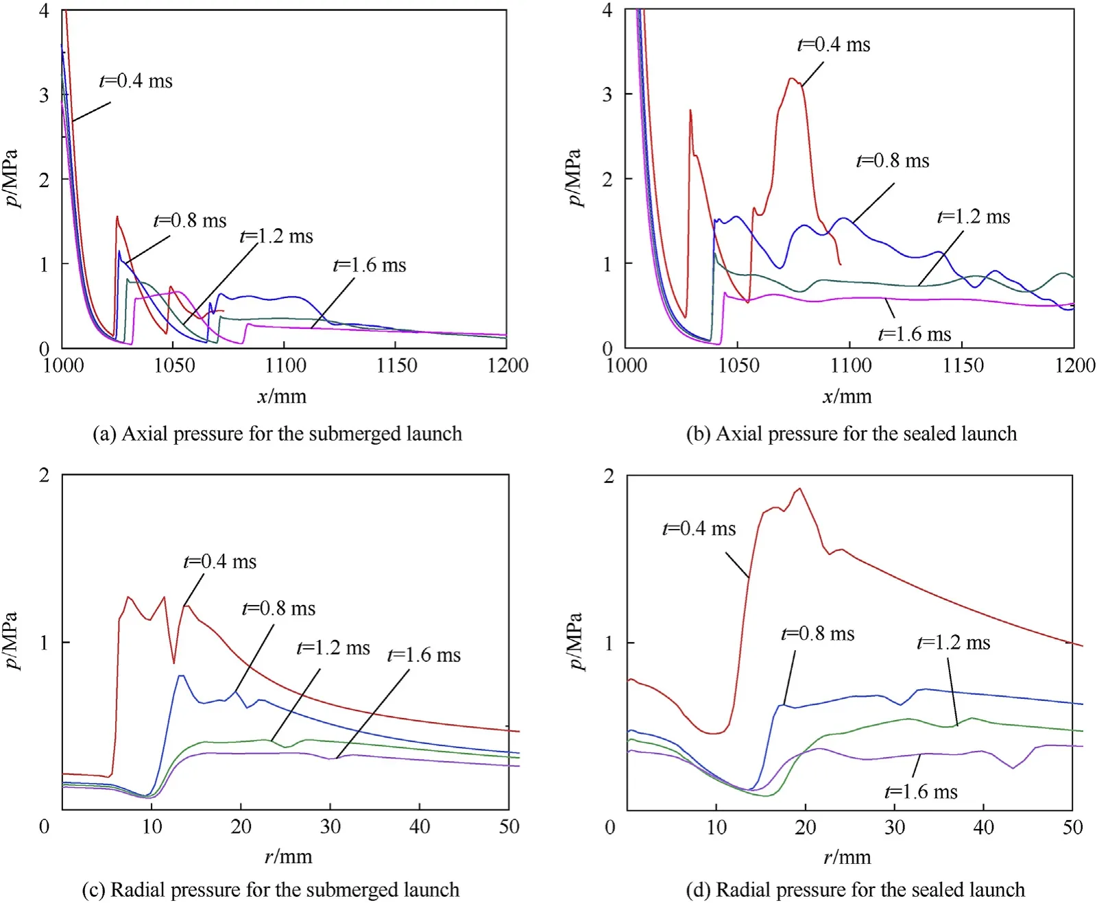
Fig.20.Muzzle pressure distributions.
In general,the pressures both at the Mach disk and the oblique shock wave for the sealed launch is significantly higher than that for the submerged launch when the bottle-shaped shock wave is formed at t=0.4 ms,but these pressures for the sealed launch are decreased more rapidly with time and finally have no difference with that for the submerged launch.For the sealed launch,the amplitude of pressure oscillations after the Mach disk is larger than the one for the submerged launch,while the duration of pressure oscillations is shorter.For example,the pressure oscillation is almost disappeared at t=0.8 ms for the sealed launch,but there is still obvious pressure oscillation at t=1.6 ms for the submerged launch.This is because the case of the sealed launch has smaller resistance before the projectile and a greater muzzle pressure.At initial,the gas is strongly compressed for the sealed launch due to the intensive collision of the gas with the surrounding water medium and the projectile bottom.As a result,the pressures both at the Mach disk and the oblique shock wave are greater,and the pressure oscillation downstream of the Mach disk is stronger.On the other hand,as mentioned above,the higher muzzle pressure and muzzle velocity for the sealed launch can accelerate the expansion of shock waves.Therefore,the shock wave expands more fully than that of the submerged launch,which makes the pressure oscillations in the flow field are decreased more quickly.
6.Conclusions
During the evolution of the underwater multiphase flow field for the submerged launch,the piston-like action of the projectile on the water column in the barrel leads to the cavitation.After the projectile leaves the muzzle,the gas is ejected from the muzzle and evolves as a Taylor cavity with a tapered head.Then,the natural cavitation occurs on the side surface of the projectile after it passes through the cavity.However,for the sealed launch,there is no cavitation before the projectile exits the barrel.The Taylor cavity is spherical,and its axial displacement is much smaller than that in the case of a submerged launch.After the projectile leaves the muzzle,the natural cavitation also occurs on its side surface.
During the sealed launch,the maximum chamber pressure is only 38% of that for the submerged launch,whereas the muzzle velocity of the projectile is 130% of that for the submerged launch.However,the velocity of the projectile dropped more rapidly after it leaves the muzzle.For both launch methods,the displacement of the projectile within the range of the muzzle flow field exhibits an exponential law with time,which is x=x-xe.
For both methods of underwater launch,a not fully developed bottle-shaped shock wave structure is formed at t=0.4 ms,but such a shock wave expands more rapidly for the sealed launch than that of the submerged launch.
For the sealed launch,the pressures at the Mach disk and the oblique shock wave are significantly higher than the pressures in the submerged launch when the bottle-shaped shock wave is formed in the muzzle flow field,which are 175% and 138% of that for the submerged launch,respectively.Compared with the submerged launch,the pressure of the sealed launch is decreased more rapidly with time,and the amplitude of pressure oscillation is larger,but the oscillation lasts shorter.
The authors declare that they have no known competing financial interests or personal relationships that could have appeared to influence the work reported in this paper.
This work was supported by the National Natural Science Foundation of China (No.11372139) and the China Postdoctoral Science Foundation (2020M681596).
- Defence Technology的其它文章
- Experimental study on propagation characteristics of rotating detonation wave with kerosene fuel-rich gas
- Adaptive robust control for triple avoidance -striking -arrival performance of uncertain tank mechanical systems
- Experimental study on WFeNiMo high-entropy alloy projectile penetrating semi-infinite steel target
- Shock wave and bubble characteristics of underwater array explosion of charges
- A micro-chip exploding foil initiator based on printed circuit board technology
- On the higher-order thermal vibrations of FG saturated porous cylindrical micro-shells integrated with nanocomposite skins in viscoelastic medium

