A numerical study of mixing intensification for highly viscous fluids in multistage rotor-stator mixers
Liying Chen,Junheng Guo,Wenpeng Li,Shuchun Zhao,Wei Li,Jinli Zhang,3,
1 School of Chemical Engineering and Technology,Tianjin University,Tianjin 300072,China
2 School of Chemical Engineering,Zhengzhou University,Zhengzhou 450001,China
3 School of Chemistry and Chemical Engineering,Shihezi University,Shihezi 832003,China
Keywords:Multistage rotor-stator mixer Computational fluid dynamics Mixing index Power consumption Distributor
ABSTRACT How to achieve uniform mixing of highly viscous fluids with low energy consumption is a major industry demand and one of the hot spots of mixing research.A typical multistage rotor-stator mixer (MRSM)equipped with a distributor was investigated to disclose the effects on the mixing performance and power consumption for highly viscous fluids via numerical simulation,considering the influence factors associated with different geometric parameters of both MRSM and the distributor.The mixing index and power consumption are used to evaluate the performance of the mixers.The dimensionless correlations for the mixing index and the power consumption are established considering the factors including the flow rate,rotor speed,the number of mixing units.Adopting the optimized mixer with the distributor(X1-T1),the mixing index increases to 0.85 (obviously higher than 0.46 for the mixer T1 without a distributor),meanwhile the corresponding power consumption is about 1/5 of that of T1 achieving the same mixing effect.It illustrates that the distributor can significantly improve the mixing of highly viscous fluids in the MRSM without the cost of large power consumption.These results would provide a guidance on the design and optimization of multistage rotor-stator mixers in industrial applications.
1.Introduction
Mixing of highly viscous fluids has been used in many fields including the food [1-3],biopharmaceutical/biotechnology [4-6],and chemical industries [7],etc.Effective mixing is crucial to improve the product quality,reduce by-products[8],enhance heat and mass transfers [9],and promote the overall performance of production processes [10].Turbulence is precluded in the process of mixing highly viscous fluids,especially when the fluids include shear-sensitive materials [11].Mixing in laminar flow is also possible for highly viscous fluids,but it is likely not to achieve desired uniformity of mixing [12].To improve the mixing performance in laminar flow,some techniques have been adopted to modify the mixers,such as installing baffles and eccentric impellers,inserting large objects [13],and so on;however,such modifications would result in large power consumptions in the mixing process.Therefore,it is imperative to explore new method for uniformly mixing of highly viscous fluids without the cost of large power consumption.
Computational fluid dynamics (CFD) simulation has been carried out to study mixing characteristics of various mixers with high viscosity fluids in the laminar flow,such as laminated internal mixer,different single screws with Maddock barrier mixers,and the double rotor continuous mixer[14-20].Additionally,Iranshahiet al.[21]adopted CFD finite element simulation method to investigate the power consumption and the mixing characteristics of Ekato Paravisc impeller with highly viscous fluids in laminar flow.Kazemzadehet al.[22] used CFD and experimental measurements to study the hydrodynamic and mixing performance with highly viscous yield-pseudoplastic fluids in coaxial mixer with different combinations of Scaba impeller and anchor impeller under the condition of laminar-transitional flow.Moreover,Chenget al.[23]used the laminar flow model to simulate the flow process with highly viscous Newtonian fluids in a horizontal self-cleaning twinshaft kneader.Liuet al.[24] numerically studied the power consumption and hydrodynamics with highly viscous Newtonian fluids in coaxial mixer with a double inner impeller in laminar flow.Guoet al.[25] studied the property of coaxial mixer consisting of anchor and turbine blades with highly viscous Newtonian and non-Newtonian fluids in laminar flow.These results suggest that the mixers with suitable configurations can promote the mixing of highly viscous fluids in laminar flow.
Various inlet configurations have been developed to intensify the mixing in microchannels [26,27].For instance,Scherret al.used T-junction inlet configuration to mix the liquids consisting of 1.5 mol·L-11,2-propanediol,1.5 mol·L-1dimethyl sulfoxide and pure water [28].However,in the view of practical production processes in industrial fields including food manufacture,polymerization fabrication,etc.,the uniform mixing is desirable for highly viscous systems,which is hard to realize only through adjusting inlet configurations.
Recently,the effects of certain distributors have been studied on the mixing performance of rotor-stator mixers with aqueous solutions,of which the viscosities had the order of magnitude about several mPa·s[29,30].For instance,Qinet al.[29]found that adding a liquid distributor can enhance the micro-mixing characteristics of aqueous solutions in the rotor-stator mixer.In addition,two patents claimed the promising applications of the mixers with a distributor.Zhang [31] claimed a mixer with two inlets for highly viscous concentrated liquids,those inlets were connected with a mixing vessel and distributor.Liu[32]claimed a mixing apparatus with an axial porous distributor to intensify the mixing of highly viscous liquids.However,no detailed information about the distributor’s structure was reported.Thus,it is essential to investigate the influences of a distributor on the mixing performance as well as the energy consumption of rotor-stator mixer for highly viscous liquids,of which the viscosity is larger than 1000 mPa·s.
Multistage rotor-stator mixer(MRSM)is popularly used for the mixing,emulsification and dispersion of multi-phased materials including liquid,solid and gas [33-36],with the feature of less dead zone[37].Recently,Wuet al.[38]performed CFD simulation of MRSM for Newtonian and shear-thinning power-law fluids to investigate the strain rate distribution and power characteristics,suggesting the promising applications of MRSM in the mixing of highly viscous fluids.
In this work,we designed a MRSM in the absence and the presence of a distributor,as displayed respectively by T1 and Dis-T1 in Fig.1,and investigated the mixing performance and power consumption for highly viscous fluidsviaCFD simulation.Influence factors including operating parameters (inlet flow rates and rotor speeds) and structural parameters (the number of mixing units,the number of rotor-stator teeth)were studied on the mixing performance.The concentration and velocity distributions were analyzed to understand deeply the mixing mechanism of highly viscous fluids under the laminar flow,meanwhile the effect of the distributor on the mixing performance was discerned.Finally,the structure of the MRSM was optimized in term of effective mixing performance and low power consumption.It would provide useful guidance on scale-up design and optimization of multistage rotorstator mixers in industrial applications.

Fig.1.Schematic diagram of multistage rotor-stator mixer with 8-teeth rotor-stator in the absence(a:T1)and the presence of the distributor(b:Dis-T1),together with the corresponding detailed structures.
2.Mixer Structures
Fig.1 indicates the schematic diagram of the MRSM with 8-teeth rotor-stator in the absence(T1)and the presence of a distributor (Dis-T1).One-stage stator and one-stage rotor constitute one mixing unit,which is defined as the number of mixing unit (s)equal 1.T1 consists of two identical inlets with each diameter of 0.03 m,an outlet with the diameter of 0.04 m,and the total number of mixing units and rotor-stator teeth equal 20 and 8,respectively.The values of geometric variables marked in the radial and axial section of T1 are listed in Table 1.In addition,the effects of the number of mixing units (s=20,30,40,50) and the number of rotor-stator teeth(n=6,8,10)on the mixing performance were studied.As the number of rotor-stator teeth (n) is changed,the cross-sectional area of the mixer is maintained as the same value in the flow direction of the fluid.
In the presence of a distributor,as shown in Dis-T1 of Fig.1(b),one fluid stream flows into the channels of the inlet 1 and exits from the trapezoidal openings,while the other fluid stream enters through two terminals of inlet 2 with the same diameter of 0.025 m.The detailed parameters of the distributor are listed in Table 2.The trapezoidal openings were designed with different length of upper (GD) and bottom sides (ED),as listed in Table 3,twelve kinds of distributors(X-,Y-,Z-series)are denoted according to the values ofGDandED.To make the discussion clear,the mixer equipped with the distributor is named according to the kind of the distributor,e.g.,X1-T1 denotes the T1 equipped with the distributor of X1,Y1-T1 denotes the T1 with the distributor of Y1,to number a few.
3.Numerical Analysis
3.1.Governing equations
With the assumption of the isothermal and steady states for incompressible fluids,the governing equations are the continuity equation and the Navier-Stokes equation.The equations were discretized through the finite volume method [22,39],and the simulations were carried out using the software of Ansys Fluent 14.0.In this work,the specific Eqs.(1) and (2) are numerically solved.

where V is the velocity vector;pis the pressure;ρ and μ are the density and dynamic viscosity of the fluid,respectively.In the simulation,the Multiple Reference Frame approach was used to model the rotating parts,the SIMPLE algorithm was used to calculate the pressure-velocity coupling,the second-order upwind scheme was applied to implement momentum and pressure discretization so as to obtain more accurate flow fields.
The normalized Reynolds numberReis used to determine the type of flow in multistage rotor-stator mixers,i.e.,it is the laminar flow whenReis smaller than 0.02,according to Kroezenet al.[40].Considering the geometry in multistage rotor-stator mixers,Recan be calculated by the following Eqs.(3)-(6) [38,40].

whereN,f,Re*,Morepresents the rotor speed,the correlation factor,the unnormalized Reynolds number and the diameter of rotor,respectively.The geometric parameters(H,L,Q*,IandB)involved in the equations are listed in Table 1.The normalized Reynolds numbers calculated from Eqs.(3)-(6)are less than 0.02 for all the operating conditions in this work.Therefore,the laminar model was used to solve the problem.

Table 1 Variables of multistage rotor-stator mixer with 8-teeth rotor-stator (marked in Fig.1(a))

Table 2 Variables of the distributor in Dis-T1 (marked in Fig.1(b))

Table 3 Geometry values of typical distributors (unit:m)
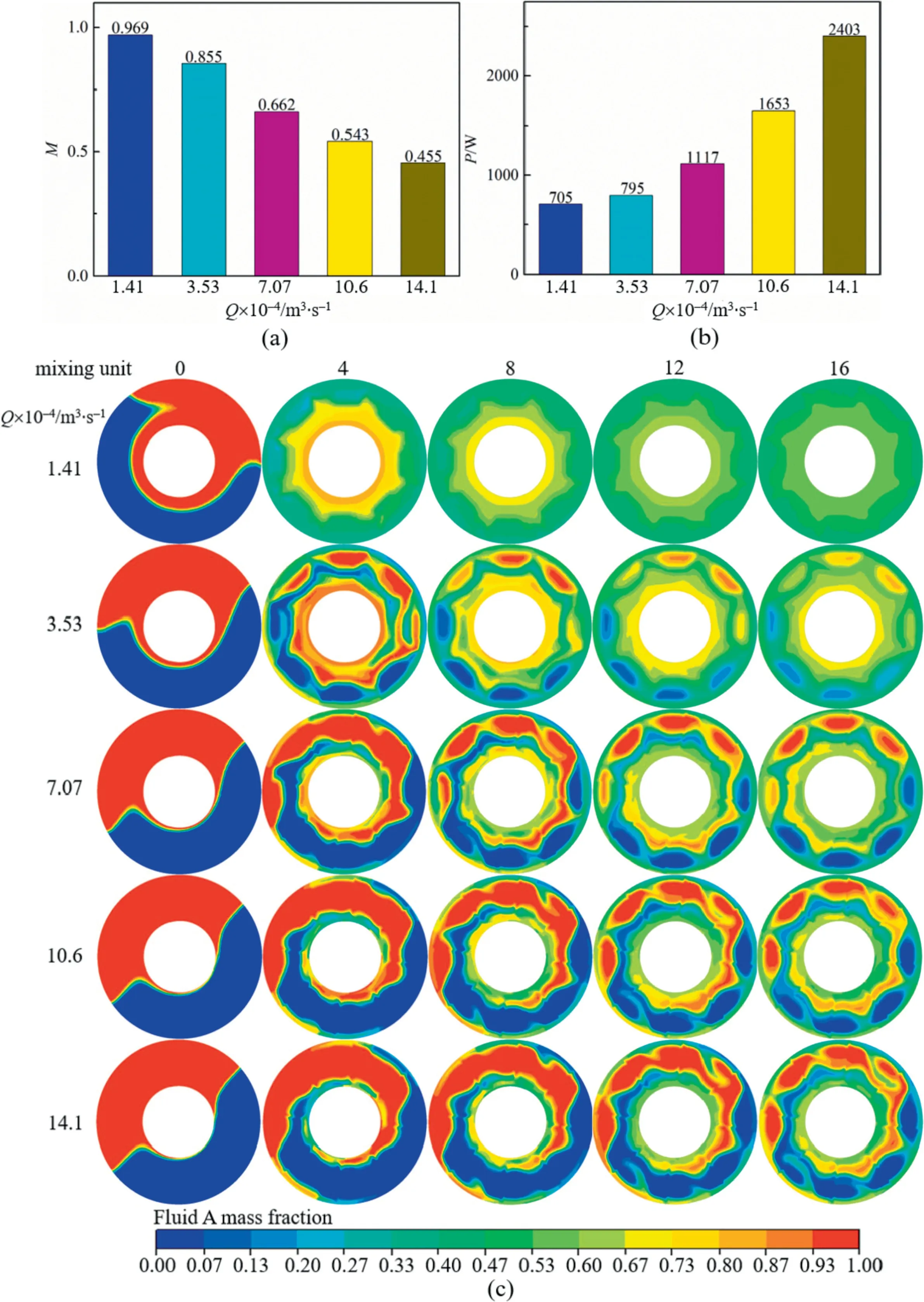
Fig.2.(a)Outlet mixing index and(b)power consumption of T1 under different total flow rates(Q).(c)Concentration contours on the x-y cross section of different mixing units of T1.(Flow rates at two inlets remain the same and the rotor speed is 3.33 r·s-1).
In order to obtain the concentration distribution of fluid species in the steady state,the convection-diffusion equation is introduced as below [41].

whereDois the molecular diffusion coefficient andCois the mass fraction of each species in the mixer.In order to investigate the mixing characteristic,two ideal highly viscous Newtonian fluids with the same physical properties,A and B,were used as the working fluid in this work.The viscosity,density and molecular diffusion coefficient are 50 Pa·s,1500 kg·m-3,1.3 × 10-12m2·s-1,respectively.The mass fraction of fluid A is 1 at the inlet 1 and 0 at the inlet 2,while fluid B is the opposite.In the process of simulation,the boundary conditions were set to the velocity inlet,the pressure outlet and the non-slip wall.
In order to quantify the mixing performance of the mixer,the standard deviation γ of mass fraction of each species and the mixing indexMat a cross section were calculated according to the following equations [42-45]:


Fig.3.(a)Outlet mixing index and(b)power consumption of T1 with different rotor speeds.The percentage of velocity in different directions on x-y cross section located two millimeters behind the fourth stator of T1 at different rotor speeds:(c)axial velocity;(d)tangential velocity;(e)radial velocity.(The total inlet flow rate is 14.1×10⁻⁴ m3·s-1 and the flow rates at two inlets remain the same).
whereciis the mass fraction of each species at the sampling pointi,is the mass fraction of each species after completely mixing andNois the number of sampling points at the section.γmaxis the maximum standard deviation at the inlet.The value ofMis in the range of 0-1,where 0 indicates the status without mixing,and 1 denotes the fully mixing status.
The total power consumptionPof the mixer is expressed by Eq.(10):

whereP1is the power consumption caused by the torque of the mixer,andP2is the power consumption caused by the pressure difference of the mixer.P1andP2can be calculated by the following equations:


whereNis the rotor speed andTis the torque of the rotor shaft,Δp1andQ1represent the liquid pressure difference and volume flow rate at the inlet 1,respectively.Δp2andQ2represent the liquid pressure difference and volume flow rate at the inlet 2,respectively.As a representative,Table S1 lists the values of Δp1and Δp2for T1,X1-T1 with the inlet1/inlet2 flow ratio of 1:1 and 9:1.
3.2.Model validation
The laminar flow model [39,46] was used to simulate the performance of mixers with highly viscous fluids.In this work,the modeling accuracy was confirmed through the comparison between the simulated power numberPowith the results measured in the supplementary experiments.On one hand,the power numberPois calculated by Eq.(13),using the power consumptionP1obtainedviaEq.(11).

Fig.4.(a)Mixing index of different mixing units of the mixer with the total 50 mixing units and(b)the power consumption of four mixers with different number of mixing units.(The total inlet flow rate is 14.1 × 10⁻⁴ m3·s-1 and the flow rates at two inlets remain the same.Rotor speed is 3.33 r·s-1, n=8).

whereDbis the diameter of the rotor.
On the other hand,a small-scaled MSRM was fabricated,as shown in Fig.S1 (in Supplementary Material),having the similar 8-teeth rotor-stator structure as T1 but the total number of mixing units equal 5,whereas the inner diameter equals 0.066 m and other parameters are scaled down accordingly.Experiments were carried out to measure the power consumption in such smallscaled MSRM under the conditions:the fluid dynamic viscosity ranged in 1.92-8.25 Pa·s,the rotational speed ranged in 3.97-16.67 r·s-1and the flow rate is 8.33 × 10⁻⁷m3·s-1.
Fig.S2 shows that the simulatedPois in good agreement with the experimental data,with the average absolute relative error of 6.7%.It confirms that the simulation method can provide the estimated results with enough accuracy.
3.3.Grid independence validation
The tetrahedral grid system used in the simulation was created by Ansys meshing.High-quality mesh is indispensable to obtain accurate calculation results [47],the grid independence test was carried out for T1,in order to ensure that the calculation results are independent of the grid size.The number of grids was used in the range of 4,001,569-23,748,038 for the simulation.Fig.S3 illustrates the effects of the grids’ number on the outlet mixing index and the torque of the mixer at 3.33 and 16.67 r·s-1when the flow rate ratio of inlet 1 to inlet 2 is 7:3 (The total inlet flow rate is 14.1 × 10⁻⁴m3·s-1).It indicates that when the number of grids is larger than 20,806,279,the change of data is very small.Taking into account the cost of the calculation,structure of T1 was simulated with the grids number of 20,806,279.
4.Results and Discussion
4.1.Mixing performance of the mixer without the distributor
4.1.1.Effects of flow rates
Fig.2(a) illustrates that the outlet mixing index of T1 increases as the total inlet flow rate decreases,suggesting that more uniformly mixing can be reached as the average residence time of the fluid becomes longer in the mixer.Previously,Patelet al.[48]obtained similar results when studying the effects of flow rates on mixing pseudoplastic fluid in the mixer with Maxblend impeller.Fig.2(b) displays that the power consumption decreases as the flow rate reduces.However,the processing capacity per unit time is significantly reduced when the flow rate becomes lower.
Fig.2(c)shows the concentration contours on thex-ycross section under different flow rates for T1.The cross section located at 0.001 m behind the shaft is denoted as 0 stage,while for the mixing unit larger than 1 the cross section is located at 0.002 m behind the corresponding stator (The relative positions of the stator and the rotor corresponding to all contours in this work have been shown in Fig.1(a)).As displayed in Fig.2(c),fluid A (shown in red color)enters from the upper inlet 1,tending to cover the shaft,and fluid B (shown in blue color) enters from the side inlet 2,having the trend to sink at the bottom.At the beginning of the entrance,two fluid streams are completely isolated,and there is only molecular diffusion between them,which is a very slow mixing process.When the fluid is stirred by the rotor,the fluid elements are stretched and reoriented in the areas near the blade [49].Hence,after being periodically sheared,squeezed and stretched by the rotor-stator,two fluid streams are superimposed and distributed in the shape of “egg roll”;consequently,the convection diffusion becomes dominant.And as the average residence time increases,the fluid is sheared,stretched,and squeezed more times by the rotor-stator,which effectively reduces the thickness of the material layer that are stacked in the shape of “egg roll”and the area of the isolation zone.Consequently,the contact opportunity between the fluids effectively increases and the diffusion distance decreases,which enhance the convection diffusion between the fluids,ultimately resulting in a more uniformly mixing.This phenomenon confirms the increasing trend of the mixing index with decreasing inlet flow rates (Fig.2(a)).
4.1.2.Effects of rotor speeds
With the increase of rotor speed,the frequency of actions of the rotor-stator on the fluid increases,the convection increases gradually,which greatly augments the contact chance of two fluid streams in the mixing zone,resulting in the better mixing performance (Fig.3(a)).Fig.3(b) illustrates that the power consumption of the mixer increases rapidly as the rotor speed increases,which is attributed to the increasing torque at high rotor speeds.Fig.3(c)shows that the axial velocity does not change significantly as the rotor speed increases;while the tangential velocity increases continuously with the increase of rotor speed (Fig.3(d));the increase of the radial velocity becomes obviously slower as the rotor speed increases.Therefore,the mixing index rises slowly,with the increase of the rotor speed.
And as they had no longer any cause for fear, they went in the old hag s house, and here they found, in every corner of the room, boxes with pearls and precious stones.53 These are even better than pebbles, said Hansel, and crammed42 his pockets full of them; and Gretel said: I too will bring something home, and she filled her apron full. But now, said Hansel, let s go and get well away from the witch s wood. When they had wandered about for some hours they came to a big lake.54 We can t get over, said Hansel; I see no bridge of any sort or kind. Yes, and there s no ferry-boat either, answered Gretel; but look, there swims a white duck;55 if I ask her she ll help us over, and she called out:
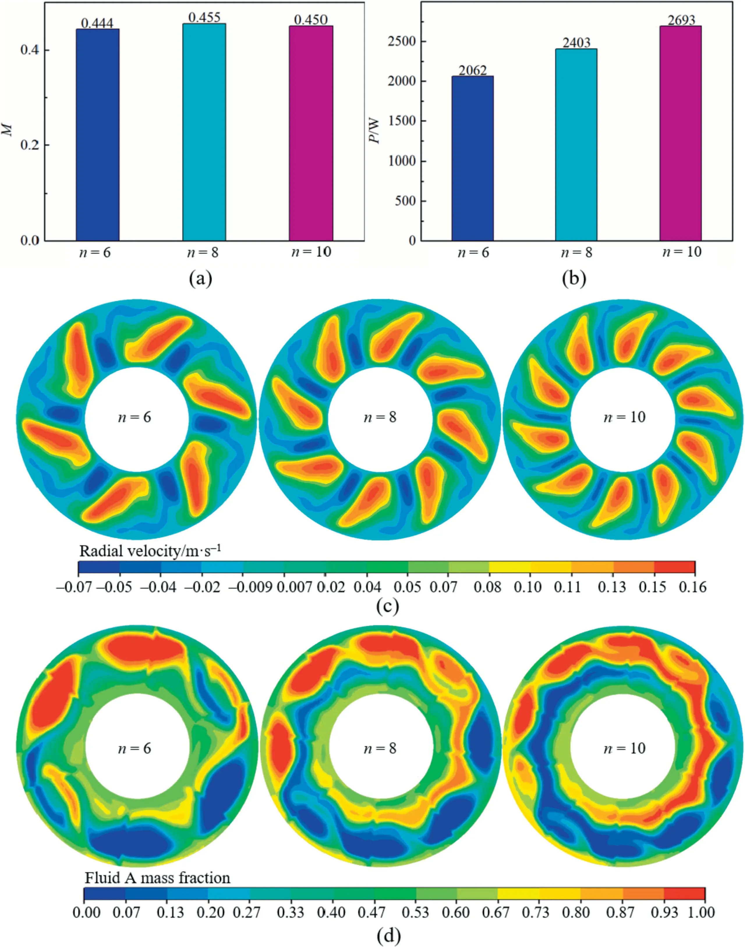
Fig.5.(a) Outlet mixing index and (b) power consumption of three mixers with different number of rotor-stator teeth.(c) Radial velocity contours on x-y cross section located two millimeters behind the fourth stator of three mixers with different number of rotor-stator teeth.(d) Concentration contours on x-y cross section located two millimeters behind the 18th stator of three mixers with different number of rotor-stator teeth.(The total inlet flow rate is 14.1 × 10⁻⁴ m3·s-1 and flow rates at two inlets remain the same.Rotor speed is 3.33 r·s-1, s=20).
4.1.3.Effects of the number of mixing units
As the number of mixing units becomes larger,both the length of the mixer and the residence time of the fluid are increased.Consequently,the fluid is sheared and stretched more times by the rotor-stator,which promotes the convection diffusion between fluids and makes the mixing more uniformly (Fig.4(a)).Fig.4(b)illustrates that the power consumption of the mixers increases almost linearly as rising the number of mixing units,while the increase of the mixing index at the outlet is not proportional to the increase of power consumption.Therefore,it would result in high cost to improve the mixing performance of the mixers only by increasing the number of mixing units.
4.1.4.Effects of the number of rotor-stator teeth
In this work,the number of rotor-stator teeth was changed but the flow area perpendicular to the fluid direction was maintained as a constant,in order to keep the average residence time of the fluid in the mixer unchanged.Fig.5(a) displays that the mixing index first increases but then decreases slightly as the number of rotor-stator teeth rises.With larger number of rotor-stator teeth,the wetting periphery of the rotor-stator teeth in the axial direction increases,resulting in high friction loss between the highly viscous fluids and the rotor-stator,and consequently larger power consumption (Fig.5(b)).Therefore,the mixing index is almost unchanged as the power consumption increases.

Fig.6.Deviations between the estimated values of M (a) and Po* (b) via the correlations and the results obtained in the simulation study for T1.

Fig.7.(a,c,e)Outlet mixing index and(b,d,f)power consumption of T1 and Dis-T1.(The total inlet flow rate is 14.1×10⁻⁴ m3·s-1 and the flow rates at two inlets remain the same.Rotor speed is 3.33 r·s-1).

Fig.8.(a)Concentration contours on x-y cross section behind different mixing units of T1 and X1-T1.(b)Mixing index of different mixing units of T1 and X1-T1.(The total inlet flow rate is 14.1 × 10⁻⁴ m3·s-1 and flow rates at two inlets remain the same.Rotor speed is 3.33 r·s-1).
The mixing of highly viscous fluids mainly relies on the macroscopic convection diffusion of different fluids caused by the shearing and stretching of the rotor.As shown in Fig.5(c),the velocity of the fluid in the radial direction increases when the number of teeth decreases.Fig.5(d) shows that at the teeth number of 6 the individual regions of each fluid are distributed alternately,which is clearly different from the elongating distribution of each fluid at the teeth number of 10.This phenomenon is reasonable in the view of two points:1) with the increase of the number of rotor-stator teeth,the effective action area,action time,shearing and stretching of a single rotor-stator tooth decrease on the highly viscous fluids,which is not conducive to the convection diffusion.2)the shear frequency of the rotor to the highly viscous fluids increases as the number of rotor teeth rises,which makes the fluid distributed uniformly along the circumference of the circle.Such bilateral effects cause slight differences in the mixing index of the mixers with different number of teeth.
4.1.5.Correlations of the mixing index and the power number
In order to guide the optimization and scale up of the multistage rotor-stator mixer,the mixing index and the power number are correlated with major parameters including the flow rate (Q),the rotor speed (N) and the number of rotor-stator mixing units(s).The obtained dimensionless correlations are as follows:

As shown in Fig.6,the predicted values by Eqs.(14)and(15)are in good agreement with the results obtained by CFD simulations.The average absolute relative error (AARE) in Fig.6(a) is 6.7%.
4.2.Effects of distributors on the mixing performance of the mixer
4.2.1.Effects of different distributors
Fig.7(a,c,e)indicate that the outlet mixing indexes of the mixers with the designed distributors are nearly twice higher than that of T1.The mixer equipped with the distributor X1,i.e.,X1-T1,appears the best.The mixing index of X1-T1 is higher than that of the mixer with 50 mixing units,however,the power consumption of X1-T1 is much smaller.As shown in Fig.7(b,d,f),the mixing index of X1-T1 at the rotor speed of 3.33 r·s-1is close to that of T1 operated at high rotor speed of 13.33 r·s-1,but the power consumption of X1-T1 is only about one-fifth of that of T1.It is reasonable since the shape of the trapezoidal openings in the distributor X1 can transport more fluids to the high linear velocity area of the rotor,making the fluids stretched fully.Further,Fig.S4 displays the concentration contours in thex-ycross section located at 0.001 m behind the distributor of X1-T1,comparing with those of Z4-T1.It indicates that in the presence of the distributor X1 the fluid is distributed mainly in the high linear velocity region around the rotor.
Fig.8(a) shows the evolution of concentration contours in thex-ycross sections for two mixers.The cross section located at 0.0028 m behind the shaft is denoted as 0 stage,while for the mixing unit larger than 1 the cross section is located at 0.002 m behind the corresponding stator.It is shown that for T1 without the distributor,two fluid streams are in an isolated state before entering the rotor-stator area.After the action of the rotor-stator,the contact area and the diffusion distance among two fluid streams only change slightly,leading to the insufficient convection diffusion in the radial and tangential directions,and consequently the slower mixing rate.
In the case of X1-T1,the fluid entering from the inlet 1 is divided into 16 strands,and the fluid entering from the inlet 2 is divided into 8 strands,thus,forming a state of alternating distribution of fluid A and fluid B.After being sheared,squeezed and stretched by the rotor-stator,the fluid becomes thinner,which further increases the contact area among two fluids and reduces the diffusion distance.The convection diffusions of the fluids in both the tangential and radial directions are stronger,therefore,the mixing rate of the fluids in the first 10 stages of X1-T1 is faster(Fig.8(b)).After the 10th stage,most parts of the fluids are mixed uniformly,and the unmixed regions of individual fluids are located apart,the convection diffusions of the fluids in the radial and tangential directions become relatively weakened,and consequently the slope of theMprofileversusthe number of mixing units is relatively smaller.
4.2.2.Effects of flow rates,rotor speeds,the number of mixing units on X1-T1
In order to compare thoroughly T1 with X1-T1,the effects of flow rates,rotor speeds,the number of mixing units on the performance of X1-T1 are studied.The results are shown in Fig.9.The dimensionless correlations were performed for X1-T1,as expressed below.
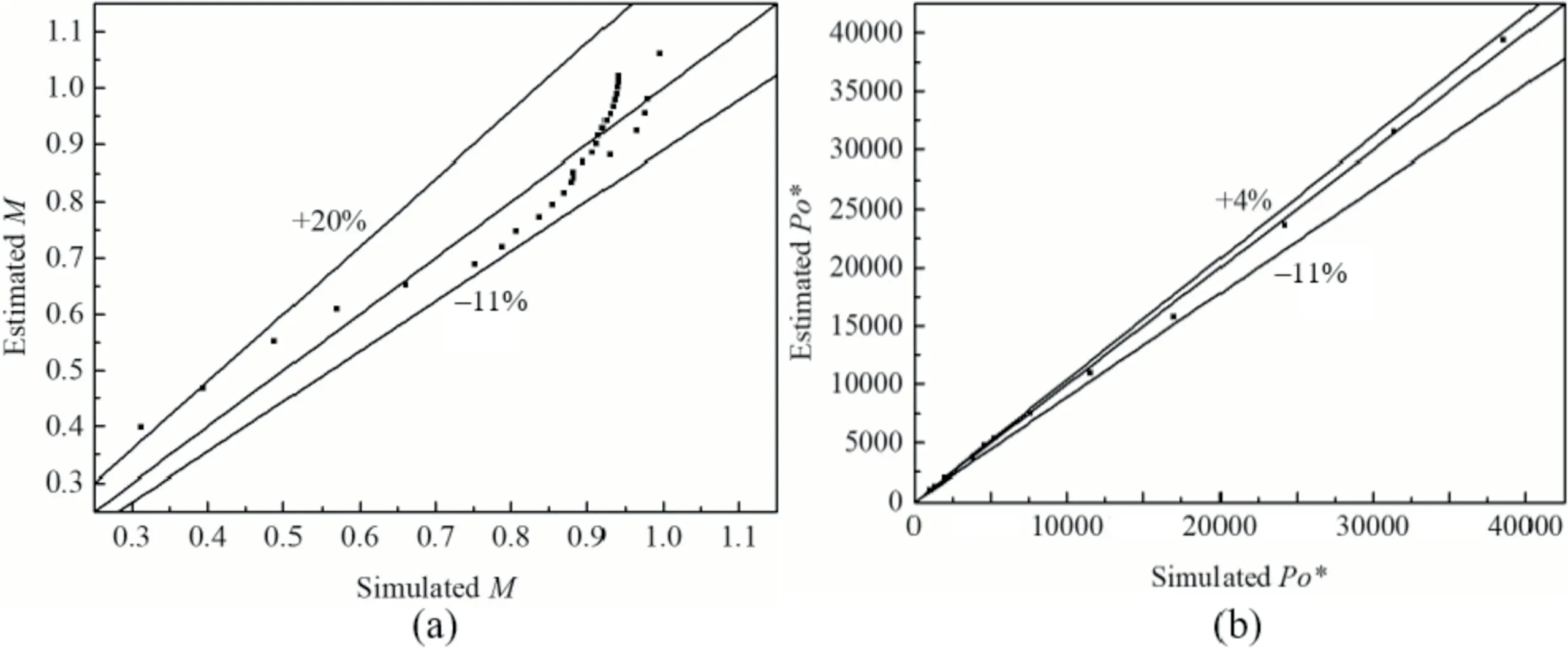
Fig.10.Deviations between the estimated values of M (a) and Po* (b) via the correlations and the results obtained in the simulation study for X1-T1.
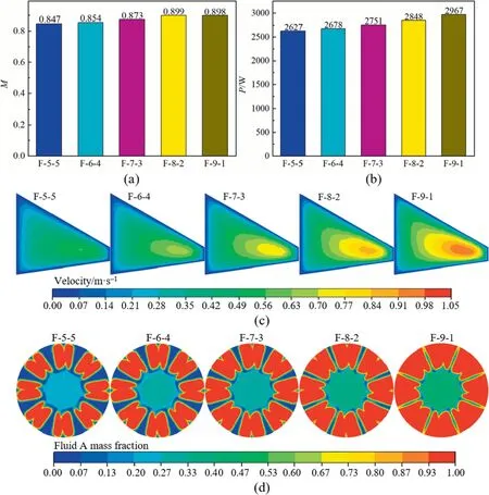
Fig.11.(a)Outlet mixing index and(b)power consumption of X1-T1 of different flow rate ratios at distributor inlets.(c)Velocity contours of trapezoidal opening section of distributor and(d)concentration contours on x-y cross section at stage 0 of X1-T1 of different flow rate ratios.(Total flow rates of two inlets are 14.1×10⁻⁴ m3·s-1 and rotor speed is 3.33r·s-1).

As shown in Fig.10,the values predicted by Eqs.(16) and (17)are in good agreement with the simulated results.The average absolute relative error (AARE) in Fig.10(a) is 6%.
4.2.3.Effects of inlet1/inlet2 flow rate ratios of X1-T1
Maintaining the constant total flow rate,Fig.11(a) illustrates the outlet mixing index of X1-T1 with different inlet1/inlet2 flow rate ratios,which is in the range of 5:5,6:4,7:3,8:2 and 9:1 (e.g.,F-7-3 denotes the inlet1/inlet2 flow rate ratio of 7:3).The outlet mixing index of the mixer has a little change as the inlet1/inlet2 flow rate ratio varies.As shown in Fig.11(b),the power consumption of the mixer increases with the increase of inlet1/inlet2 flow rate ratio.The reason is that the fluid is subjected to large resistance when passing through the channel of the inlet 1 of the distributor,and the resistance becomes larger when more amounts of fluids pass through the distributor.Fig.11(c) indicates that at larger inlet1/inlet2 flow rate ratios the high-speed zone at the openings of inlet 1 of the distributor increases,which enhances the convection diffusion in the mixer.Decreasing the inlet 2 flow rate can make the contact area among two fluids increased(Fig.11(d)),which is beneficial to intensify the mass transfer.Therefore,with the increase of inlet1/inlet2 flow rate ratio,the above two effects result in somewhat increase of mixing index.
5.Conclusions
A typical MRSM equipped with certain distributor was investigated to disclose the effects on the mixing performance and power consumption for highly viscous fluids via CFD simulation,considering the influence factors associated with different geometric parameters of both MRSM and the distributor.The correlations for the mixing index and the power consumption are established considering the factors including the flow rate,rotor speed,the number of mixing units.And the number of rotor-stator teeth has little effect on the mixing performance of the mixer.Adopting X1-T1,the mixing index increases to 0.85 (obviously higher than 0.46 for the mixer T1 without a distributor),meanwhile the corresponding power consumption is about one-fifth of that of the mixer T1 achieving the same mixing effect.It illustrates that the distributor can significantly improve the mixing of highly viscous fluids in the MRSM without the cost of large power consumption.For X1-T1,the research results of changing the flow rate ratio of two inlets show a small effect on its mixing performance.These results will provide a reference for the design,optimization and industrial application of multistage rotor-stator mixers.
Declaration of Competing Interest
The authors declare that they have no known competing financial interests or personal relationships that could have appeared to influence the work reported in this paper.
Acknowledgements
This work was financially supported by the National Natural Science Foundation of China (22090034,21776179),the Major Science and Technology Project of Xinjiang Bingtuan(2020AA004) and the Major Project of Shihezi City(2020ZD002).
Supplementary Material
Supplementary data to this article can be found online at https://doi.org/10.1016/j.cjche.2021.08.012.
 Chinese Journal of Chemical Engineering2022年7期
- Chinese Journal of Chemical Engineering的其它文章
- Chemical reduction-induced fabrication of graphene hybrid fibers for energy-dense wire-shaped supercapacitors
- Preparation of aldoxime through direct ammoximation using titanium silicalite-1 catalyst
- Efficient synthesis of tyrosol from L-tyrosine via heterologous Ehrlich pathway in Escherichia coli
- N,P co-doped porous graphene with high electrochemical properties obtained via the laser induction of cellulose nanofibrils
- Two-stage cyclic ammonium sulfate roasting and leaching of extracting vanadium and titanium from vanadium slag
- Conjugation of a zwitterionic polymer with dimethyl chains to lipase significantly increases the enzyme activity and stability
