
Plasma–wave interaction in helicon plasmas near the lower hybrid frequency
2022-08-01 05:59:10YideZhao赵以德JinweiBai白进纬YongCao曹勇SiyuWu吴思宇EduardoAhedoMarioMerinoandBinTian田滨
Chinese Physics B 2022年7期
Yide Zhao(赵以德), Jinwei Bai(白进纬), Yong Cao(曹勇), Siyu Wu(吴思宇),Eduardo Ahedo, Mario Merino, and Bin Tian(田滨),†
1Science and Technology on Vacuum Technology and Physics Laboratory,Lanzhou Institute of Physics,Lanzhou 730000,China
2School of Mechanical Engineering and Automation,Harbin Institute of Technology,Shenzhen 518055,China
3Equipo de Propulsi´on Espacial y Plasmas(EP2),Universidad Carlos III de Madrid,28911 Legan´es,Spain
Keywords: helicon plasmas,lower hybrid frequency,power deposition
1. Introduction
Helicon waves propagating near lower hybrid frequencies in plasmas have been significantly studied since the 1970s.[1,2]It plays an important role in space plasmas and fusion research due to the close relation to the ion heating and the lower-hybrid drift instability.[3–5]In the 1980s,the investigation of influence of lower hybrid frequencies in plasma discharges was studied by Boswell and Zhu.[6,7]They found that a very dense plasma can be produced near lower hybrid frequencies with helicon waves. After that, the extensive studies on lower hybrid frequencies for the helicon discharge were carried out by many researchers.[8–11]
The lower hybrid frequencyωlhis a resonant frequency between the electron cyclotron frequencyωceand the ion cyclotron frequencyωciand has the following form:[12]
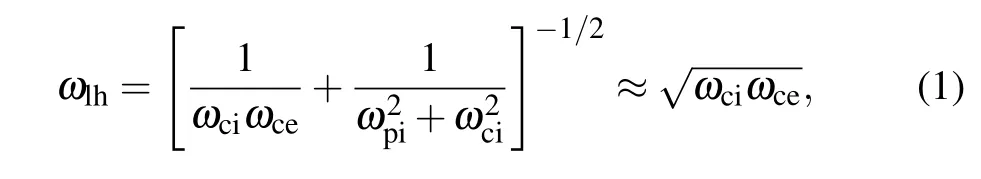
whereωpirepresents the ion plasma frequency.Near the lower hybrid frequency,the effect of ion motion cannot be neglected.The basic wave theory shows that the resonance occurs when the frequency reachesωlh.[13]It is expected to be beneficial for the power deposition. The experimental results by Yunet al.[8,14]confirmed this prediction. They tested the frequency dependence of helicon plasmas for different magnetic fields and various gases. It was shown that the optimum frequency yielding the highest plasma density is near the lower hybrid frequency and it was suggested that the lower hybrid resonance heating may be important in helicon sources.[8]However, the optimum frequency is not exactly equal toωlhbut slightly lower. This may be explained by the Doppler shift effect.[8]
In order to study the role of the lower hybrid frequency in helicon discharges, Cho gave the self-consistent results coupling the wave equations to the global balance equations.[13]He found that there are many eigenmodes when the operation frequency is higher thanωlh, but there are only a few isolated eigenmodes for frequencies lower thanωlh. Furthermore, an eigenmode always exists near the lower hybrid frequency. This behavior leads to the variation of the resistance with the frequency. Specifically, the self-consistent results show that the abrupt density jump occurs near the lower hybrid frequency. These conclusions were also confirmed in the experiments by Kwaket al.[15]Moreover, in the study of the instabilities and anisotropy in the hot-helicon experimental device(HELIX),Scimeet al.[16]found that there is a clear increase in electron temperature as the antenna frequency is near the lower hybrid frequency. Additional experimental results obtained by Balkeyet al.[10]indicated that the maximum electron density is measured when the rf frequency is near the lower hybrid frequency. It is consistent with the previous results by others. However, the maximum ion temperature is measured whenω <0.7ωlh. It is suggested that the mechanism of power deposition for ions and electrons in helicon sources is distinct. When studying very light ion mass gases such as hydrogen, Moriet al.[11]found that the optimal frequency can be away fromωlhin a non-uniform magnetic field as long as the RF power is large enough.In addition,the experiments by Buttenschonet al.[17]showed that the linear scaling of the plasma density with magnetic fields can be observed in the frequency range ofωlh≤0.8ω.
Therefore, the lower hybrid frequency and its resonance occurring plays a vital role in helicon plasmas. However, the influence of the parameters on the lower hybrid resonance has not been fully studied.In this paper,a detailed(0D)dispersion relation of helicon plasmas is derived to investigate the characteristics of wave propagation and the power deposition near the lower hybrid frequency.A 1D cylindrical plasma–wave interaction model is established to study the wave property and the parametric investigations are carried out to analyze the influence of the applied magnetic fields,plasma density and RF frequency on the helicon plasmas.
The structure of this paper is as follows. The basic theory is implemented in Section 2. Section 3 presents the simulation results and discussion. The conclusion is given in Section 4.
2. Theory
2.1. The(0D)dispersion relation
In order to analyze the plasma–wave interaction near the lower hybrid frequency,the dispersion relation is discussed in detail. In a magnetized plasma,the general dispersion relation is very complicated. To understand the wave properties, we limit the study to linear waves, of single frequencyωpropagating into a plasma where an axially stationary magnetic fieldB0is applied. The plasma–wave response is assumed to vary as exp(ik·r-iωt) and is governed by the Maxwell equations:
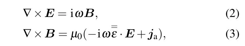
whereEandBrepresent only the RF-related electromagnetic field,jais the external current density from the antenna.Fourier expansion in time has been applied,and all magnitudes are expressed in complex form.In addition,=εis the plasma dielectric tensor. For a cold weakly collisional plasma, it takes the form[18]

with the elements
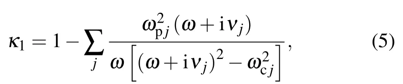
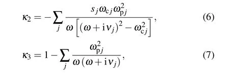
whereωcjandωpjare the cyclotron and electrostatic frequencies(of speciesj=i,e),νjis the collision frequency andsjis the sign of the electric charge. When the emission frequency is near the lower hybrid frequency,the influence of ions on the plasma–wave interaction cannot be neglected. The ion mass has to be taken into account in the dieletric tensor. Simplifying Eqs.(2)and(3),the dispersion relation in helicon plasmas can be written in a biquadratic form[18]
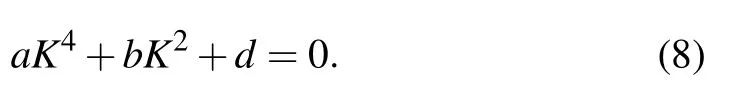
Here, we introduce the normalized parameterK=kde, with the wavenumberk,the electron skin depthde=c/ωpeand the light speed in vacuumc. This non-dimensional parameter includes the influence of the wavenumberkand the electron densityne. It is convenient to carry out the parametric analysis. In addition,a,banddare coefficients related to the dielectric tensor components
whereθis the angle betweenB0andk. Parallel and perpendicular wavenumbers are defined ask‖=kcosθandk⊥=ksinθ. Also,the normalized element of dieletric tensor is

To solve this dispersion relation, the basic characteristics of helicon waves can be analyzed. Two pairs of solutions for this biquadratic equation represent two branches of waves,named as the helicon (HE) mode and the Trivelpiece–Gould (TG)mode.[19]The helicon mode is an electromagnetic wave with long wavelength. In contrast,the TG mode is an electrostatic wave and has a larger perpendicular wavenumberk⊥than the helicon mode,hence shorter wavelength is achieved.
2.2. The 1D plasma–wave interaction model
In this section, the 1D cylindrical model available is established to investigate the plasma–wave interaction in helicon plasmas. Based on the assumption in the derivation of the dispersion relation, more conditions due to the geometry and practice are taken into account. We consider a cylindrical source of lengthLand radiusrpfilled with a fully ionized plasma. The radial variation of the plasma density,n=n(r),is known. The plasma source is surrounded by an antenna,which is assumed to be infinitely thin and located atr=ra,withra>rp.The plasma is confined radially by the applied axial magnetic fieldB0,created by a set of external coils(which are assumed to have no effects on the plasma–wave interaction). The whole set is immersed in a larger conducting vessel of lengthLand radiusrwwithrw>ra.
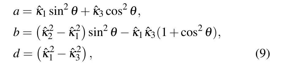
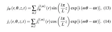
For a finite length cylinder source,the plasma is bounded by conducting plates at both ends. Therefore, the reflection boundary conditions are achieved at the two conducting end walls. Then,the components of EM fields can be expanded in the following(z,θ)Fourier series,[20]
wherek‖=kl=lπ/Lis the parallel wavenumber;mis integer,andlis natural.
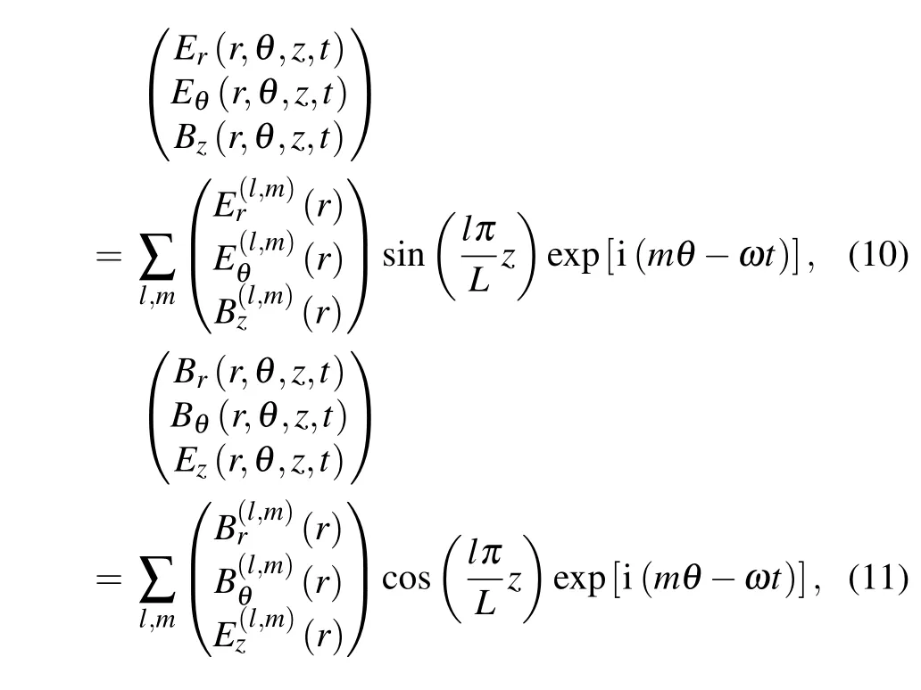
Considering the geometry of the antenna, the general form of the current density is
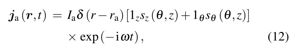
whereIais the antenna current;szandsθdefine the linear shape of the antenna.[21]This current density is also expanded as
Therefore, the current density for different types of antennas can be obtained due to the geometry and corresponding Fourier expansion.In order to simplify the Maxwell equations,we introduce the following dimensionless variables:
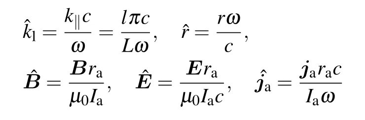
and phase modified fields
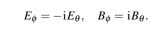
Using these relations,Eqs.(2)and(3)can be expanded to the four differential equations for each(l,m)mode:
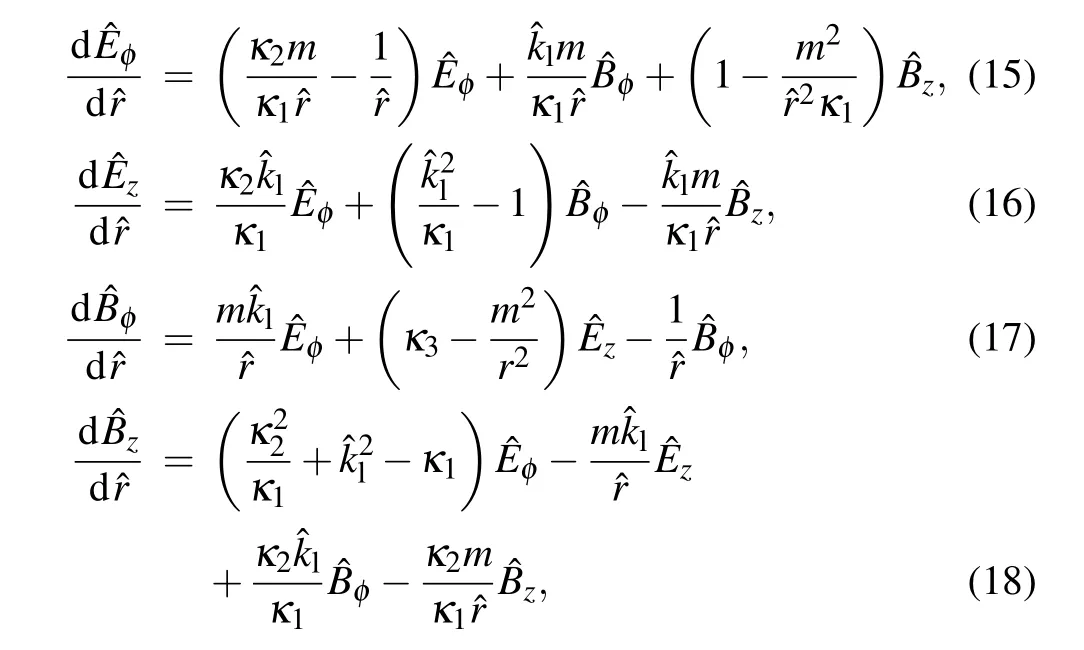
and the two algebraic equations:
Thus,this equation system has been simplified to an ordinary differential problem. Considering different situations of plasmas, the methods for obtained solutions are distinct. In radially uniform plasmas, the solutions of this equation system can be obtained analytically. All EM field components can be expressed as the combination of Bessel functions or modified Bessel functions.[22]In non-uniform plasma density case,the equations system has to be solved numerically. The 4-and 5-th order Runge–Kuta method is applied to obtain the solutions. This cylindrical 1D plasma–wave model has been introduced by researchers and verified by comparing with the experiments.[20,23,24]
2.3. Power deposition in the plasma
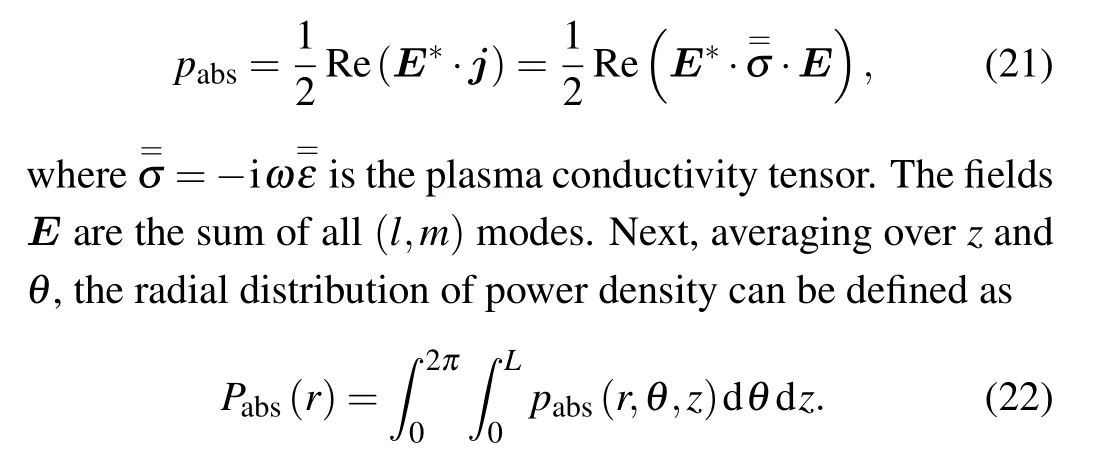
Once all EM fields are obtained, the power absorption by plasmas is taken into account. In this work, the helicon plasma has a high plasma density and relatively low electron temperature. Therefore,the collisional damping is considered as the main mechanism of wave dissipation and neglects the kinetic effects, such as Landau damping.[25]In our 1D wave model,it is assumed that the antenna wire is a perfect conductor and no power loss occurs inside the antenna.[26,27]Thus,all power emitted by the antenna is absorbed in the plasma column. Then, the time-averaged power density absorbed by the plasma at a given location(r,θ,z)is[20]
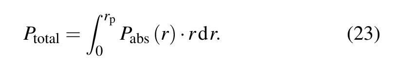
Then, the total absorbed powerPtotalis the integration of the whole plasma volume
Therefore,according to Joule’s law,the plasma resistanceRis given as
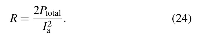
The plasma resistance is used to evaluate the performance of the RF antenna coupling with the plasma column.
3. Results and discussion
With the purpose of studying the plasma–wave interaction near the lower hybrid frequency, simulations are based on a typical geometry of the helicon source.[28]The gas is argon, the radially cold, uniform plasma and axial static magnetic field are taken into account. The half-turn helical antenna,which has been widely used in laboratory,is applied in simulations.The expression of the current density is written as a function of the (l,m) modes.[29,30]The validation and convergence of the(l,m)modes have been carried out in a large range of (l,m) mode withm=[-151,151] andl=[1,200].Thel=[1,30]andm=[-9,9]are selected to ensure that the convergence of(l,m)mode is achieved. In addition,only odd number ofmmodes for the helical antenna is excited in terms of the geometry of the antenna.[31]Then,the main parameters are summarized in Table 1. These parameters are used in all calculations,except for the one whose variation is being studied.
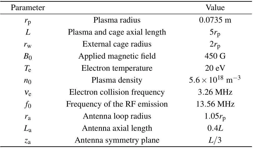
Table 1. Summary of input data for the plasma–wave interaction simulations.
3.1. Wave propagation and power deposition
In this subsection,the investigation of the wave propagation and power deposition near the lower hybrid frequency is carried out. We first discuss the feature of the wave propagation according to the dispersion relation.
Figure 1 gives the relation betweenωce/ωandk⊥decalculated by Eq.(8). It shows the perpendicular wavenumber as a function of the ratioωce/ωat a fixed plasma density. The parallel wavenumberk‖= 17.1 (l= 2) is selected, and the corresponding dimensionless parameterk‖deis 0.0384. The collision and collisionless cases are also considered. In the collisionless case,there are two roots fork⊥,representing the helicon wave and the TG wave.[32]At low values ofωce/ω,it is seen that there is no real solution fork⊥. It illustrates that no wave propagates in this regime. Withωce/ωincreasing,two kinds of waves, helicon mode and TG mode, propagate.The value of the wavenumber of two waves is close at the beginning and then TG mode goes up rapidly and has a much largerk⊥than the helicon mode. As the ratioωce/ωcontinues to increase,the perpendicular wavenumberk⊥for the slow wave(TG wave)tends to be infinite whenω=ωlhandk⊥of the fast wave(HE wave)becomes very small. This means that the resonance will occur near the lower hybrid frequency and the power absorption in plasmas is expected to have a local maximum whenωis close toωlh.
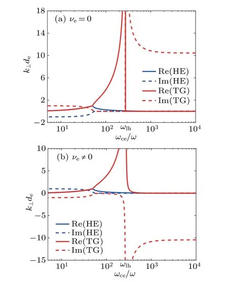
Fig. 1. The perpendicular wavenumber k⊥versus the ratio ωce/ω.The plasma density is 5.6×10¹⁸ m-3; the parallel wavenumbers k‖is 17.1 m-1 and the corresponding dimensionless parameter k‖de is 0.0384. In the collisional case, the electron collision frequency νe is 3.26 MHz. The blue lines represent the helicon wave and the red lines stand for the TG wave.The solid and dashed lines represent the real and imaginary parts,respectively. The magnitude of TG wavenumber is too large to display with the given scale near the region where ω ~ωlh.
For the collisional case,the basic trend is consistent with the collisionless case and there are some differences caused byνe. The sign of imaginary part of two waves is changed. This is because the collision frequency is the damping rate in the dielectric tensor and contributes to the imaginary part. In addition,there is a knee in the profile of TG mode near the lower hybrid frequency,and it does not becomes zero suddenly like the collisionless case. This may cause the resonance to change slightly near the lower hybrid frequency and can be used to explain the frequency shift in the experiments.[8]
Based on the analysis of the dispersion relation, the distribution of wave fields and the corresponding power density near the lower hybrid frequency is given in Figs.2 and 3, respectively. The magnetic field isB0=2000 G and the value ofωlh/ωis 1.53. It is shown that the wave fields in the bulk region of the plasma is small and only has a large amplitude near the boundary. This phenomenon is consistent with the results of the wavenumber given in Fig.1. When the frequencyωis close toωlh, the wavenumber of helicon mode becomes zero and TG mode tends to be infinite. Therefore, the wave can hardly propagate in the center of the plasma and is only damped quickly near the boundary. The radial power density shown in Fig. 3 further confirms this conclusion. The power deposition in the bulk region of the plasma is trivial and the main contribution concentrates in a very thin layer near the boundary. This also provides the evidence of the resonance whenωreachesωlh.
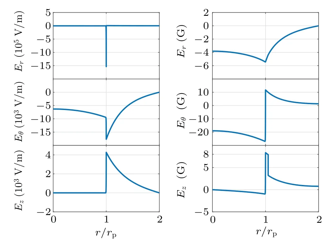
Fig. 2. Radial profiles of electromagnetic fields at θ = 0, z = L/4,B0=2000 G,n0=5.6×10¹⁸ m-3 and I0=15 A.
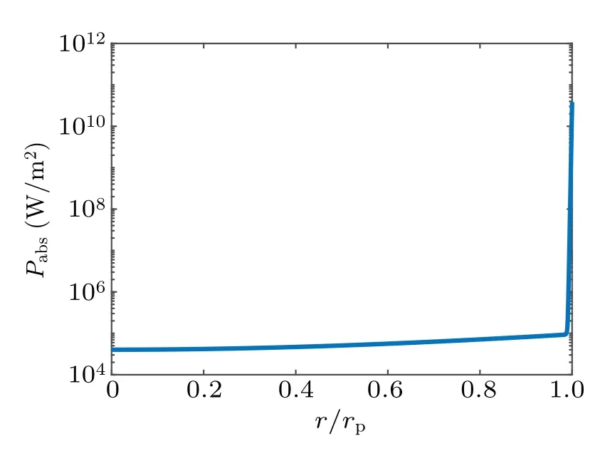
Fig.3. Power absorption distribution in the radial direction for the case of Fig.2.
3.2. Parametric investigation
In this subsection, the parametric investigation of the power deposition near the lower hybrid frequency is achieved.The influences of the RF frequency, applied magnetic fields and the plasma density on the power deposition are analyzed.
Figure 4 shows the plasma resistance versus the magnetic field for differentlmodes and plasma densities, and the RF frequency is fixed.As is seen,the resistance whenω <ωlhhas numerous local peaks in the regime of two waves propagating.Then, when the lower hybrid frequency is near the wave frequency, the plasma resistance presents few sharp peaks. This can be explained by the existing eigenmodes nearωlhproposed by Cho.[13]Forl=2 the resistance is up to 15.08 Ω.However, for differentlmodes, the peak location changes with the magnetic field and the plasma density. It can be explained by the dispersion relation of Eq.(8). The perpendicular wavenumber is effected by theB0andn0and leads to the variation of the eigenmodes. Therefore,the corresponding local peak varies.
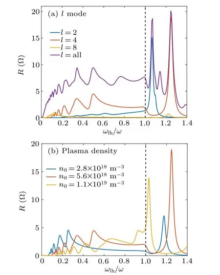
Fig.4. Resistance profiles varying with the ratio ωlh/ω. The RF frequency is fixed at 13.56 MHz. The magnetic field is varied. (a) The case for different l modes,with the plasma density 5.6×10¹⁸ m-3. (b)The results for different plasma densities with l=4.
Figure 5 represents the 2D color maps of resistance varying with the magnetic field and plasma density. The different wave propagation regimes are separated by the dashed line,and the solid lines are the separatrix of the lower hybrid frequency. Below the red solid line, we can see numerous local peaks in the two wave propagating regimes.The linear relation between the magnetic field and plasma density for the plasma resistance is achieved. This can be explained by the dispersion relation of helicon plasmas[22,33]and has been confirmed in the experiments.[32,34]
Near the lower hybrid resonance, several isolated peaks of resistance emerge and the linear relation between the magnetic field and plasma density for the local peaks still holds.There is a transition near the lower hybrid frequency. The linear slope for the peaks is changed and the values of these peaks are much higher than the peaks below the separatrix,because of the resonance. Near the lower hybrid frequency,the perpendicular wavenumber of TG wave goes to infinity.The resonance dominates the behavior of wave propagation.Hence, the larger power deposition is achieved. In Fig. 5(d),alllmodes are taken into account. More local peaks lie in the regime above the red line. This also confirms that the resonance is the main mechanism of the power deposition for helicon plasmas whenωis nearωlh.
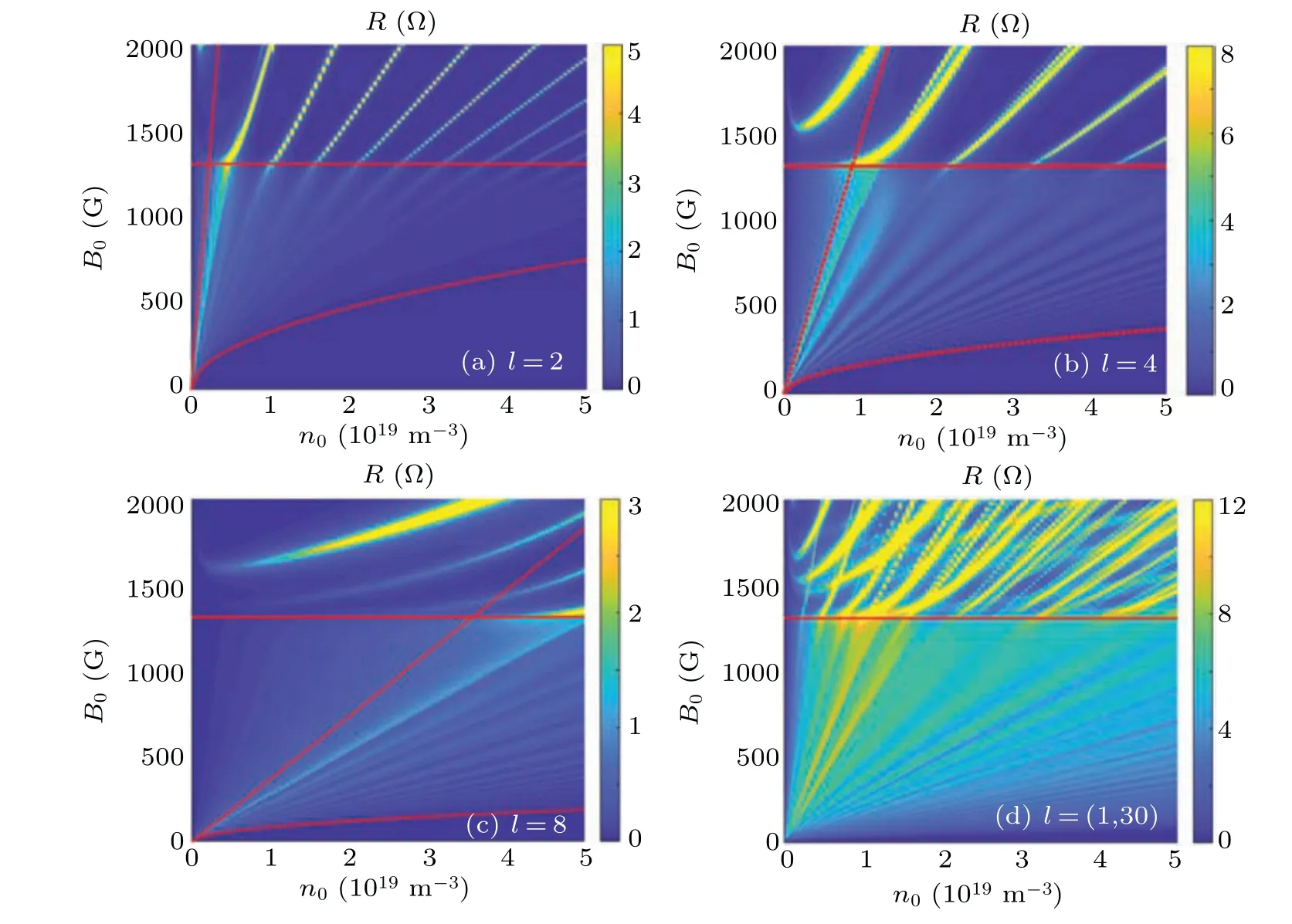
Fig. 5. The 2D color map of resistance varying with both the magnetic field and plasma density for different l modes. The red dashed line represents the different wave propagation regimes and the red solid line is the separatrix of the lower hybrid frequency.
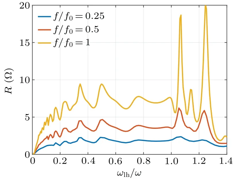
Fig. 6. Plasma resistance versus magnetic field and wave frequency.The resistance is as a function of magnetic field with different frequencies. The nominal frequency f0 is 13.56 MHz.
Figure 6 gives the resistance for different RF frequency as a function of magnetic fields. Alllmodes are taken into account. The local peaks appear in the case ofω <ωlh. The higher applied frequency is applied, the higher resistance is achieved, provided that the magnetic field increases proportionally. Near the lower hybrid resonance, there is a larger local peak of the resistance. This keeps consistence with the previous results. Additionally,we can observe the monotonic dependence of the resistance with the antenna frequency in terms of Eq. (21). At a fixedωlh/ω, the power absorption is larger when the emission frequency is increasing.
4. Conclusion
The(0D)dispersion relation and the 1D radially plasma–wave interaction model have been established to investigate the characteristics of the plasma–wave interaction near the lower hybrid frequency. The wave propagation near the lower hybrid frequency are described according to the dispersion relation of helicon plasmas. The power deposition mainly concentrates on a thin layer near the boundary. Furthermore, the parametric investigation is illustrated. When the frequency is near the lower hybrid frequency, the plasma resistance can reach a local peak because of the lower hybrid resonance.The resonance is effected by the plasma density and parallel wavenumber and leads to the frequency shifting of the local peak. The linear relation between the magnetic field and the plasma density is still satisfied but a transition leads to a change of slope. The plasma resistance is increasing when the emission frequency is larger and the relation between the frequency and magnetic field is linear.
Acknowledgements
Project supported by the Open Fund for Science and Technology on Vacuum Technology and Physics Laboratory, Lanzhou Institute of Physics (Grant No. ZWK1703).The authors also acknowledge the support of the National Natural Science Foundation of China (Grant No. 51907039) and Shenzhen Technology Project (Grant Nos. JCYJ20190806142603534 and ZDSYS201707280904031).The contribution of E.Ahedo and M.Merino has been supported by the ESPEOS project(Grant No. PID2019-108034RB-I00/AEI/10.13039/501100011033),funded by the Agencia Estatal de Investigaci´on (Spanish National Research Agency).

- Chinese Physics B的其它文章
- Solutions of novel soliton molecules and their interactions of(2+1)-dimensional potential Boiti–Leon–Manna–Pempinelli equation
- Charge density wave states in phase-engineered monolayer VTe2
- High-pressure study of topological semimetals XCd2Sb2(X =Eu and Yb)
- Direct visualization of structural defects in 2D semiconductors
- Switchable down-,up-and dual-chirped microwave waveform generation with improved time–bandwidth product based on polarization modulation and phase encoding
- Machine learning potential aided structure search for low-lying candidates of Au clusters