Bimetallic Metal-Organic Framework with High-Adsorption Capacity toward Lithium Polysulfides for Lithium–sulfur Batteries
Pengbiao Geng, Meng Du, Xiaotian Guo, Huan Pang* , Ziqi Tian*, Pierre Braunstein, and Qiang Xu*
1. Introduction
Metal-organic frameworks (MOFs), also called coordination polymers,are crystalline materials constructed by coordination of organic linkers to metal ions.[1,2]MOFs are well-known for their remarkable features,including high-porosity and -adsorption capacity for some gases and noxious solutes.[3–5]Owing to these physicochemical properties,MOFs have attracted increasing attention for various applications in energy storage devices,[6]brackish water desalination,[7,8]electrocatalysis,[9,10]and others.[11–13]Recently, the application of MOFs to immobilize sulfur and adsorb lithium polysulfides (Li2Sx, 4 ≤x ≤8) in lithium–sulfur(Li-S)batteries has attracted increasing interest. Through a solvothermal method followed by a sonication process, Park et al. obtained a UiO-66/Nafion composite onto polyethylene as separator for Li-S batteries.[14]Guo et al.designed ultrathin 2D MOF-Co nanosheet composites as an interlayer in the anode side to anchor polysulfides and suppress their crossovers.[15]
Among Li-based batteries,[16–18]Li-S batteries have a high-theoretical specific capacity(1675 mAh g-1) due to sulfur, resulting from the conversion of sulfur to Li2S4and Li2S.[19,20]Furthermore, the sulfur electrode materials are abundant in the earth.[21]However, the major issues associated with the cathode in Li-S batteries are the drastic volume change on going from sulfur to Li2S4, Li2S, and the “shuttle effect” of soluble intermediate Li2Sxthat causes the progressive leakage of active material from the cathode,resulting in short life cycle of the battery.[22–24]One strategy consists in dispersing sulfur into porous carbonaceous host materials to physically confine them, as exemplified by the work of Dong et al.[25]However, it was recognized that the physical confinement of polar Li2Sxin nonpolar carbon materials was not enough to prevent its dissolution and the shuttle of polysulfides from the cathode to the anode.[26]To address the issue,Park et al.designed an ingenious route to disperse sulfur into GOs, which obtained a nano-sulfur solution to prepare a homodisperse R-GO/nS hybrid.[27]Recently,researchers have focused on materials that can enable strong dipolar interaction,such as the interaction between sulfiphilic Cu2+ions and polysulfides.[28]It turns out that MOFs not only have porous structures for sulfur incorporation, but also can contain metal ions acting as Lewis acid sites to chemically adsorb Li2Sx.
As a subclass of MOFs, the MIL series have the advantages to be of low cost,easy to prepare,and non-toxic.(Al)MIL-53 as a common Al-MOF, of chemical formula Al(OH)[O2C-C6H4-CO2]•[HO2C-C6H4-CO2H]0.70, was firstly synthesized by Ferey’s team[29,30]and its 3D framework is interconnected by 1,4-dicarboxybenzene (BDC) groups.It forms highly porous networks and owns a high-pyrolysis temperature(275°C).For our purpose,vast porous network for sulfur implantation and high-pyrolysis temperature for MOF/sulfur melt-diffusion process feature this MOF as a promising sulfur host. However, as the structural model of Al-MOF shows(Figure S1),Al3+is six-coordinated and coordinatively saturated,unable to bind extra polysulfides.To genfunctional theory (DFT) calculations indicated that the Al/Cu-MOF could overcome the “shuttle effect,” as evidenced by their excellent adsorption capacities.Clearly,the novel strategy(Lewis acid-base interaction), different from the conventional physical confinement, developed in this work for the adsorption of polysulfides appears most promising.erate additional binding sites for the polysulfide anions(S)and suppress the “shuttle effect”, MOF materials are considered to modify through incorporation of additional metal ions with high-binding energy with Li2Sx. In recent years, Cu2+has been considered as an effective metal ion for anchoring polysulfides due to its sulfiphilicity.Zhou and co-workers utilized Cu3(BTC)2@GO as an interlayer to construct ionic sieve membranes.[31]We reasoned that four-coordinated Cu2+ions would have a high-binding tendency withto effectively prevent the dissolution of Li2Sxgenerated in the cyclic discharge/charge process.In such bimetallic MOFs,Cu2+would not only function as an ionic crosslinking agent,but also as a chemical binding agent for polysulfide anions.[32–34]
Based on the above consideration,we selected Al-MOF as sulfur host material and sulfiphilic Cu2+as the second metal ion to effectively immobilize Li2Sxand suppress its dissolution.A one-step hydrothermal method was designed to prepare bimetallic Al/Cu-MOF as an advanced cathode material and the resulting sulfur-loaded electrode material(Al/Cu-MOF-S)delivered a high-initial capacity of 974.2 mAh g-1at 0.1 C,which is higher than that delivered by monometallic Al-MOF.Furthermore,to explore the influence of the amount of Cu2+present,samples with different Cu2+contents were prepared by controlling the Al3+:Cu2+molar ratio. The macroscopic permeation test and density
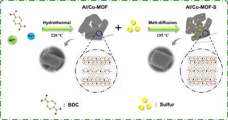
Figure 1. Schematic diagram of Al/Cu-MOF-S synthesis.
2. Results and Discussion
The bimetallic Al/Cu-MOF investigated in this work were synthesized by a one-step hydrothermal method at 220°C.In the synthetic process,through changing the Cu2+content, we prepared a series of samples,labeled as Al/Cu-MOF-n (where n indicates the Cu2+molar quantity;for the details see Supporting Information). To facilitate comparisons,the coordination polymer Al-MOF and Cu-1,4-dicarboxybenzene (Cu-MOF) were prepared. Sulfur injection into the free space of the Al-MOF, Al/Cu-MOF-n, and Cu-MOF was performed using a simple melt-diffusion method (the obtained samples were named as Al-MOFS, Al/Cu-MOF-n-S, and Cu-MOF-S). The overall preparation process is schematically illustrated in Figure 1, and the details are provided in
Supporting Information.
Figure S2 shows the powder X-ray diffraction (PXRD) patterns of the samples, and the diffraction peaks of Al-MOF (ht) are consistent with those in the literature.[35]The atomic coordination model in Figure S1 indicates the 3D framework is formed by the trans chains of sharing AlO4(OH)2octahedra and the chains are linked by BDC groups, which is favorable for polysulfide injection. The diffraction peak at 2θ = 8° in the PXRD patterns clearly indicates the successful complexation reaction. Cu-MOF diffraction peaks were obtained from the literature.[36]After impregnation of sulfur in MOFs, the PXRD patterns of Al-MOF-S, Al/Cu-MOF-S displayed the weak peaks of orthorhombic sulfur phase(Figure S2),confirming the impregnation of sulfur in MOF structure (the peaks of Al/Cu-MOF-1, Al/Cu-MOF-1-S, Al/Cu-MOF-10, and Al/Cu-MOF-10-S are shown in Figure S3). However, the Cu-MOF-S pattern displayed obvious orthorhombic sulfur peaks comparing with Cu-MOF,indicating most sulfur powder left the outside of Cu-MOF.
Solid-state nuclear magnetic resonance(NMR)spectroscopy was utilized for demonstrating the structural information variation with Cu2+introduction.To investigate the chemical composition of Al-MOF, Al/Cu-MOF, and Cu-MOF,1H magic angle spinning (MAS) NMR experiments were conducted. The signal at 7.2 ppm can be assigned to the aromatic protons linker BDC in the1H MAS NMR spectra of Al-MOF, Al/Cu-MOF-5, and Cu-MOF (Figure S4). The resonance at 2.7 ppm results from the Al-OH-Al bridges in Al-MOF, which shifts from 2.7 to 2.4 ppm after introducing Cu2+. Owing to the interference of strong magnetism of Cu2+,the1H MAS NMR data of Cu-MOF shows no distinct chemical shift peaks.

Figure 2. SEM images of a,b) Al-MOF, c,d) Al-MOF-S, e,f) Al/Cu-MOF-5, g,h) Al/Cu-MOF-5-S. i) STEM image and elemental mapping analysis of Al/Cu-MOF-5-S.
Scanning electron microscopy(SEM)images of the prepared samples for Al/Cu-MOF-5(Figure 2e and f) show that the quasirectangular morphology resembles that of Al-MOF (Figure 2a and b) and the particle sizes of Al-MOF and Al/Cu-MOF-5 are uniform. It can be deduced that the introduction of Cu2+could not change the overall morphology and particle size of Al-MOF.After the sulfur impregnation process,the morphology of Al-MOF-S (Figure 2c and d), Al/Cu-MOF-1-S (Figure S5c and d),Al/Cu-MOF-5-S(Figure 2g and h),and Al/Cu-MOF-10-S(Figure S5g and h) show no distinct change compared with Al-MOF, Al/Cu-MOF-1 (Figure S5a and b), Al/Cu-MOF-5 (Figure 2e and f), and Al/Cu-MOF-10 (Figure S5e and f) owing to the high thermostability.Besides, no residual sulfur agglomeration was observed from all SEM images of sulfur-loaded samples, indicating that the sulfur amount (ca.60 wt.%) was appropriate. It can be deduced that the introduction of Cu2+could not result in the change of sulfur amount.The SEM images of Cu-MOF in(Figure S6a and b)show a rod-like structure.After loading sulfur,the morphology of Cu-MOF-S(Figure S6c and d)illustrates most sulfur powder was adhered on the surface. The scanning transmission electron microscopy(STEM)images and an elemental mapping analysis established the uniform distribution of sulfur and Cu2+in Al/Cu-MOF-5-S (Figure 2i). In particular, the Cu2+mapping image demonstrates the uniform distribution of Cu2+in the framework of Al/Cu-MOF-5 synthesized by the one-step hydrothermal method.
To explore the elemental composition and valence states in the samples, X-ray photoelectron spectroscopy (XPS) measurements were performed. Five characteristic peaks located at 74.17, 164.31, 284.66,530.98,and 934.3 eV(Figure S7)correspond to the Al 2p,S 2p,C 1s,O 1s,and Cu 2p peaks,respectively.Cu signals were not found in Al/Cu-MOF-5 and Al/Cu-MOF-5-S. This is due to the limited survey thickness and low-atomic amount in the crystal structure. The highresolution S 2p spectra could be deconvoluted into three peaks (Figure S8) at 163.67, 164.85, and 165.09 eV,corresponding to S-S,Sat.,and S-C bands, respectively. The pore-size distributions of the MOFs were revealed by N2adsorption isotherms at 77 K(Figure S9-S12)and the sulfur impregnation into Al-MOF and Al/Cu-MOF-5 clearly led to a decrease of N2adsorption capacity(Figure S9 and S10),with the pores being occupied by sulfur. Interestingly, Cu-MOF presented the lowest N2adsorption ability, demonstrating its limited free space for sulfur injection. The pore-size distribution curves, calculated by the Barrett–-Joyner–Halenda method, of the MOF host materials (Figure S11 and S12), show a broad mesopore (~2.5–32 nm) distribution, which is beneficial for the storage of sulfur particles and polysulfides in the porous structures of the MOFs.[37,38]
To evaluate the impact of the immobilization of sulfur in the MOFs and the presence of sulfiphilic Cu2+in Al/Cu-MOF,the electrochemical performance of Al-MOF-S, Al/Cu-MOF-S, Cu-MOF-S, and S-Super P(sulfur without host materials, see details in Supporting Information)cells, assembled with Li foils and 1.0 M LiTFSI as the electrolyte, were investigated(details of the Li-S cell preparation are provided in Supporting Information). The cyclic voltammetry (CV) curves of Al/Cu-MOF-5-S and Al-MOF-S cells under the voltage window of 1.7–2.7 V at a scan rate of 0.1 mV s-1(Figure 3a and Figure S15) show distinct reduction peaks at~2.34 and~2.01 V,assigned to the conversion of S8molecule to high-order soluble polysulfides and their further transformation to Li2S2and Li2S. The oxidation peaks at ~2.41 and ~2.26 V correspond to the conversion of Li2S2and Li2S to sulfur molecule(Equations 1 and 2):
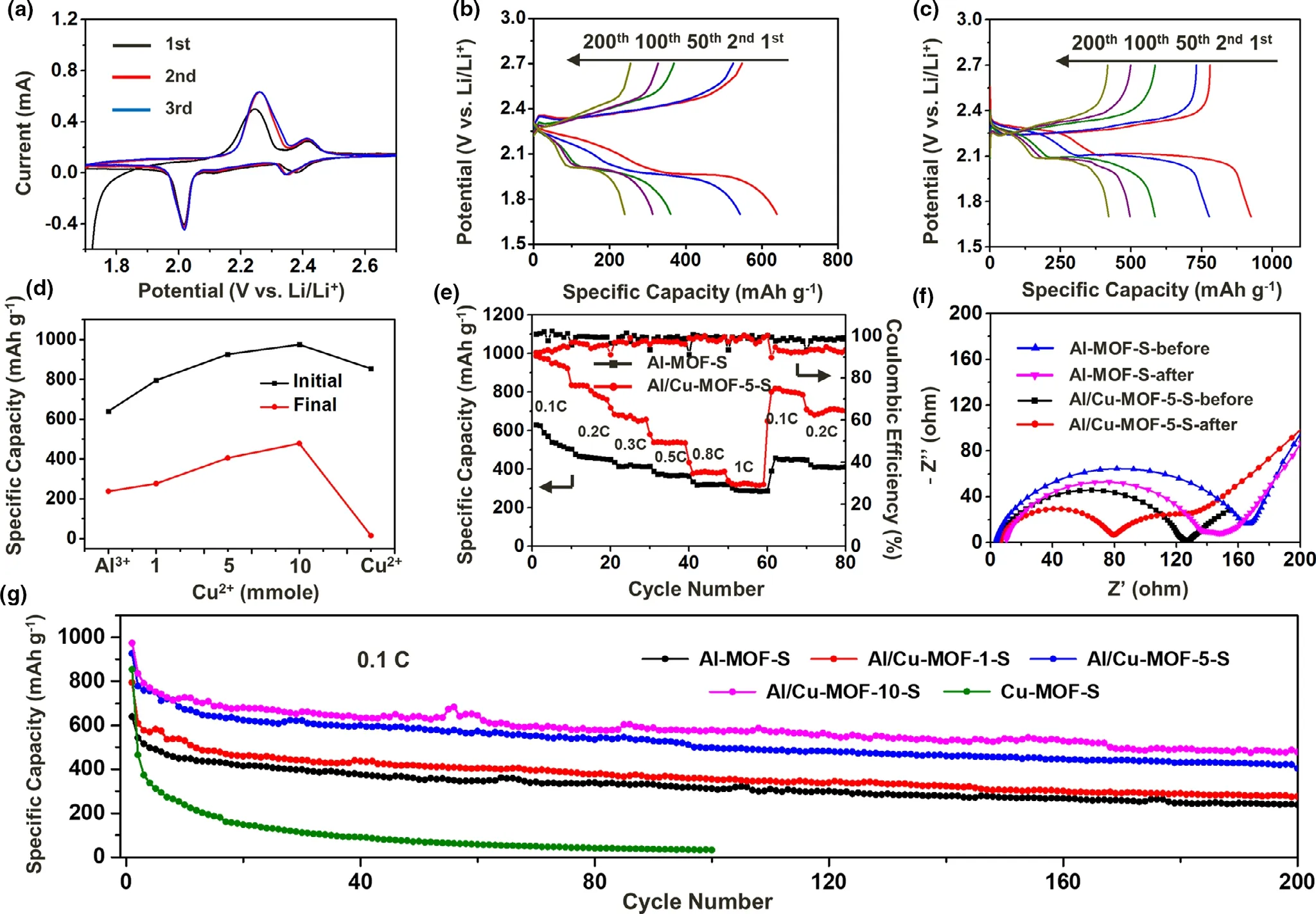
Figure 3. a) CV curves of the initial three cycles of Al/Cu-MOF-5-S electrode at a scan rate of 0.1 mV s-1. b) GCD profiles of Al-MOF-S at 0.1C. c) GCD profiles of Al/Cu-MOF-5-S at 0.1C. d) Comparison of specific capacities in different Cu2+-content samples with Al-MOF and Cu-MOF. e) Rate performances of Al-MOF-S and Al/Cu-MOF-5-S with the corresponding coulombic efficiencies at different discharge rates. f) Nyquist plots of Al-MOF-S and Al/Cu-MOF-5-S electrode before and after 200 cycles. g) Cyclic performance of Al-MOF-S, Al/Cu-MOF-1-S, Al/Cu-MOF-5-S, Al/Cu-MOF-10-S, and Cu-MOF at a constant rate of 0.1 C.

The well-echoed peaks indicate the reversible electrochemical reactions that occurred in the electrode materials.[39]Subsequently,the electrochemical stability was indicated by their galvanostatic charge/discharge(GCD)test between 1.7 to 2.7 V at 0.1(1 C = 1675 mA g-1).The accurate sulfur mass fractions in Al-MOF-S and Al/Cu-MOF-5-S were calculated from the thermogravimetric analysis (TGA) curves (Figure S13 and S14),and the elemental analysis data(Table S2).Figure S16 and Figure 3b,c show the GCD profiles of the S-Super P,Al-MOF-S,Al/Cu-MOF-5-S electrodes at 0.1 C, and the initial discharge specific capacities are 597.8,639.5,and 974.2 mAh g-1,respectively,indicating the improved specific capacity of Al/Cu-MOF-S than Al-MOF-S.
By comparing with the GCD profiles of Al-MOF, Al/Cu-MOF-1-S,Al/Cu-MOF-5-S,and Al/Cu-MOF-10-S at a current density of 0.1 C,it is clear that the specific capacities of Al/Cu-MOF-S-n are all competitive.Besides, the initial specific capacity of S-Super P (Figure S16a) can achieve 597.8 mAh g-1and keep 298.8 mAh g-1after 200 cycles,which are evidently lower than Al/Cu-MOF-n-S. The GCD profiles of Al-MOF-S, Al/Cu-MOF-S, and Cu-MOF at 0.5 C are presented in Figure S17, indicating the high-rate performance. These electrochemical results can be ascribed to the direct contact between the sulfur molecule and the organic electrolyte,resulting in fast capacity fading.All the GCD profiles of MOF-S samples experienced two distinct plateaus at about 2.33 and 2.05 V (vs Li+/Li), which are almost consistent with the reduction peaks in the CV curves.[40]However,the S-Super P GCD profiles show no discharge plateaus during the incipient cycles, probably due to the polarization of sulfur in electrolyte.Generally,the high-sulfur loading on the cathode will decrease the specific capacity to a degree.Considering the factor, we further evaluated the cyclic performance of Al/Cu-MOF-5 with a cathode possessing a high-sulfur loading of 2.1 mg cm-2(Figure S20).After 400 cycles,the Li-S batteries showed a high-reversible capacity of 324.4 mAh g-1at 0.5 C,with a slight capacity attenuation.[41]In order to clearly display the improved electrochemical performance of the Al/Cu-MOF-n-S comparing with Al-MOF and Cu-MOF electrodes,Figure 3d presents the comparison of initial specific capacities with those after 200 cycles at 0.1 C.The rate performance is a well-acknowledged indicator for batteries.Therefore,the Al-MOF-S and Al/Cu-MOF-5-S electrodes were cycled at various charge/discharge rates:0.1,0.2,0.3,0.5,0.8,and 1.0 C,and then back to 0.1 C and 0.2 C.The specific capacities of Al/Cu-MOF-5-S surpassed those of Al-MOFS (Figure 3e), as indicated in the corresponding GCD profiles (Figure S19). Following the common electrochemical energy storage law,the highest specific capacity should be achieved at the lowest discharge rate and should decrease as the discharge rate increases.[42,43]Moreover,the cyclic performance of different MOF-S electrode materials was tested at 0.1 C and 0.5 C(Figure 3g and Figure S18).The decreasing capacity at a high-discharge rate can be attributed to the limited free space available for Li+ions in the electrode materials.[44]The resistance of Al-MOF-S and Al/Cu-MOF-5-S was investigated by electrochemical impedance spectroscopy (EIS) (Figure 3f). Before the cycling process, the semicircular diameter of Al/Cu-MOF-5-S was smaller than that of Al-MOF-S,indicating that the charge-transfer resistance of Al/Cu-MOF-5-S was improved by the introduction of Cu2+.After 200 cycles,the resistances of Al-MOF-S and Al/Cu-MOF-5-S decreased owing to the deposition of Li2S2and Li2S into electrolyte.
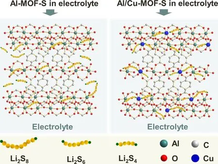
Figure 4. Schematic illustration for the lithium polysulfides binding with Al-MOF and Al/Cu-MOF.
The specific capacity comparison in Figure 3d shows that the improved capacity of Al/Cu-MOF-5-S to Al/Cu-MOF-10-S cannot achieve that of Al/Cu-MOF-1-S to Al/Cu-MOF-5-S, which is ascribed to the saturation of Cu2+in Al-MOF determined by the limited replacement of Al3+. The inductively coupled plasma-optical emission spectrometry (ICP-OES) data in Table S1 shows an almost identical concentration of Cu2+in Al/Cu-MOF-5 and Al/Cu-MOF-10, verifying the above hypothesis. To further clarify the corresponding microstructural stability after long-term cycling,SEM images at different cycles of Al/Cu-MOF-5-S electrode were examined (Figure S21). As the cycle number increases,the morphology of Al/Cu-MOF could keep the intact morphology. Compared with traditional porous carbon host materials,the metal nodes(Lewis acidic sites)and the porous structure,resulting from the connecting organic functional groups, can provide effective binding sites for the lithium polysulfides and strongly confine them within the MOF pores.[45–47]The interaction mechanism in the Al-MOF and Al/Cu-MOF host materials is shown in Figure 4. When Al-MOF is used as the sulfur host,the generated Li2Sxis almost completely dispersed in the electrolyte owing to the low-binding energy among Al3+/Li2Sxand few binding sites for Li2Sx. In contrast, with Al/Cu-MOF as the cathode host materials, Li2Sxmolecules could be readily captured by Cu2+, resulting from its strong binding energy with Sn2-and the lower steric hindrance, as compared to that of the sixcoordinate Al3+. In particular, the porous framework offers a platform for effectively restraining the dissolution and diffusion of polysulfides at the molecular level.To clearly compare the improved electrochemical performance of the Al/Cu-MOF-S electrode,Table S3 displays the contrastive specific capacity in contrast with other MOFs as host materials.
To further evaluate the adsorption capacity of Al/Cu-MOF-5 toward lithium polysulfides, 20 mg of Al/Cu-MOF-5 and Al-MOF powders were separately immersed in 3 mL 10 mmol L−1Li2S4solution, and the color change with time was recorded. The preparation detail of Li2S4solution presented in Supporting Information. As shown in Figure 5a, the color of the solution containing the Al/Cu-MOF-5 powder became almost transparent after 12 h due to the strong adsorption capacity of Al/Cu-MOF-5 to Li2S4. In contrast, almost no discoloration was observed for the Al-MOF, consistent with its low-adsorption ability. Moreover, the change of concentration in the Li2S4supernatants was analyzed by ultraviolet-visible (UV-vis) spectroscopy.The absorption intensity at ca. 410 nm of the Al/Cu-MOF-5 supernatant after 12 h is weaker than that of Al-MOF after 27 h(Figure 5b). Furthermore, the interaction between the host and Li2S4was confirmed by XPS analysis (Figure 5c). The Li 1s high-resolution spectra of the Al-MOF and Al/Cu-MOF-5/Li2S4mixture exhibit a characteristic feature at 55.10 eV, corresponding to the Li-S bond in Li2S4. The Al-O signal in Al/Cu-MOF (Figure 5d) appears a small negative shift than Al-MOF owing to the decreased binding energy between Al and O atoms after replacing Al with Cu atoms partly. The high-resolution S 2p spectra (Figure 5e) indicate the valence state change of S after Li2S4adsorption.The peaks in Al-MOF located at 161.68,163.10 eV, and 163.58 eV can be attributed to terminal sulfur (ST-1), S-S and S-C,respectively. The newly emerged S2-signal located at 167.95 eV is attributed to the intermediate Li2S4.[48]The positive binding energy shift of S-S and S-C could be ascribed to the increased electron cloud density between the metallic center with Li2S4due to the introduction of Cu2+. The above-mentioned result demonstrates that the Al/Cu-MOF hosts can effectively encapsulate Li2S4into their cavity to form inclusion complexes.
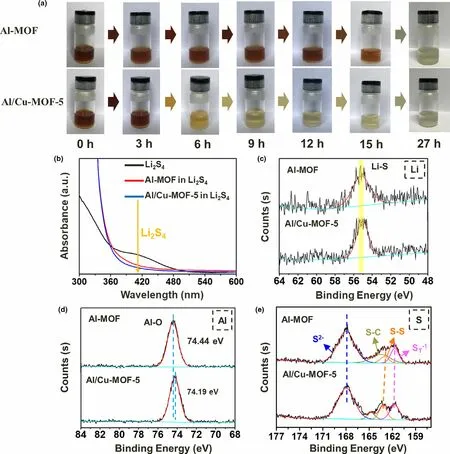
Figure 5. a) Optical photos of Li2S4 solution permeation tests of Al-MOF and Al/Cu-MOF-5 powers. b) UV-vis absorption spectra of pure Li2S4 solution and the supernate adding Al-MOF and Al/Cu-MOF-5 powers in 10 mmol L-1 Li2S4 (Al-MOF after 27 h and Al/Cu-MOF-5 after 12 h). c-e), Li 1s, Al 2p and S 2p XPS spectra of Al-MOF and Al/Cu-MOF-5 powers after lithium polysulfide permeation tests.
We employed DFT calculations to gain more insight into the improved performance of Al/Cu-MOF in lithium polysulfides adsorption. Simulation models were built based on Al-MOF-ht supercell. As shown in Figure 6a and b,one-eighth of the Al3+cations are replaced with Cu2+. In order to keep the total charge neutral, one bridging hydroxyl group should be removed,creating two coordinatively unsaturated metal nodes.For pristine Al-MOF,the binding energies to Li2S4,Li2S6,Li2S8,and S8molecules are −1.17,−1.36,−1.81,and −1.27 eV,respectively, whereas after replacement by copper cations, the binding energies increase to −1.59,−1.73, −2.46,and −1.49 eV (Figure 6e),respectively. The MOF-Li2S8complex structure is illustrated in Figure 6c and d. The enhanced interaction is commonly considered to be related to the improved performance of the Li-S battery and we assumed that coordinatively unsaturated cations would behave as strong Lewis acid sites, strongly binding to polysulfides. In fact, the replacement of the lower-valent Cu2+by higher valent Al3+induces an internal dipole which contributes to the framework-polysulfides interaction.Moreover, compared to the strong metal–sulfur bonds, this weaker,non-bonding interaction makes the battery system more recyclable.
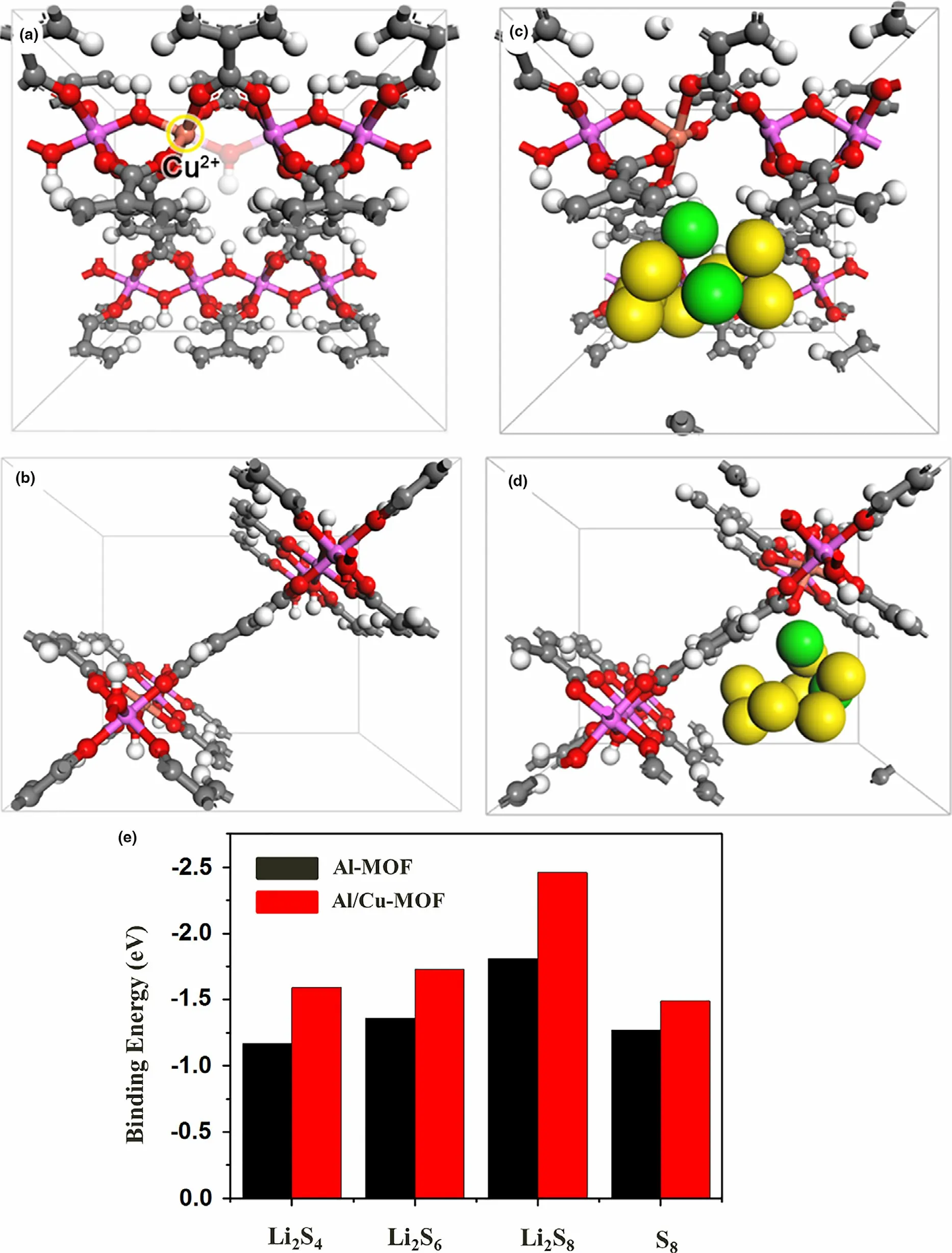
Figure 6. a,b) Different views of the structure of Al/Cu-MOF. The Cu2+ cation is highlighted in yellow circle and the removed OH group is in shadow. c,d)Different views of the structure of the Al/Cu-MOF-Li2S8 complex. e) Comparison of binding energies of lithium polysulfides to Al-MOF and Al/Cu-MOF. The polysulfides are depicted in CPK (Corey-Pauling Koltun) model. Color code: C, gray; H, white; O, red; Al, purple; Cu, brown; Li, green; S, yellow.
3. Conclusion
A high-efficiency host material was synthesized through a one-step hydrothermal method to suppress the detrimental “shuttle effect”. The improved electrochemical performance of the Li-S battery was confirmed, and the explanations offered were supported by DFT calculations. Compared with the physical sulfur adsorption occurring with porous carbon host materials, the chemical immobilization (Lewis acidic–basic sites) could provide effective binding sites for the lithium polysulfides and strongly confine them within the MOF pores. The incorporation of electropositive Cu2+cations had a significant and beneficial influence on the intrinsic properties of Al-MOF. Consequently,the assembled Li-S batteries with the Al/Cu-MOF-n-S cathode exhibited the higher specific capacity than Al-MOF-S and maintained a final specific capacity. Furthermore, samples with different Cu2+contents were prepared and even a small quantity of Cu2+was found to have a positive effect.This work combined for the first time the benefits of porous Al-MOF and sulfiphilic Cu2+to construct new bimetallic MOF host materials for polysulfides. It is expected that this strategy could be extended to the preparation of other host materials with high-lithium polysulfide-adsorbing capacities for use as advanced electrode materials in Li-S batteries.
Acknowledgements
This work was supported by the National Natural Science Foundation of China(U1904215), Natural Science Foundation of Jiangsu Province (BK20200044),Changjiang scholars program of the Ministry of Education(Q2018270),the Postgraduate Research & Practice Innovation Program of Jiangsu Province(KYCX20_2805).
Conflict of Interest
The authors declare no conflict of interest.
Supporting Information
Supporting Informationis available from the Wiley Online Library or from the author.
Keywords
lithium polysulfides, lithium–sulfur batteries, metal-organic frameworks,shuttle effect, sulfiphilic Cu2+
Received: January 10, 2021
Revised: April 1, 2021
Published online: April 5, 2021
[1] W. Xu, X. Pei, C. S. Diercks, H. Lyu, Z. Ji, O. M. Yaghi, J. Am. Chem. Soc.2019, 141, 17522.
[2] L. Zou, C.-C. Hou, Z. Liu, H. Pang, Q. Xu, J. Am. Chem. Soc. 2018, 140,15393.
[3] X. Cao, C. Tan, M. Sindoro, H. Zhang, Chem. Soc. Rev. 2017, 46, 2660.
[4] A. K. Mondal, K. Kretschmer, Y. Zhao, H. Liu, C. Wang, B. Sun, G.Wang, Chem. - A Eur. J. 2017, 23, 3683.
[5] Y.-B. Zhang, H. Furukawa, N. Ko, W. Nie, H. J. Park, S. Okajima, K. E.Cordova,H.Deng,J.Kim,O.M.Yaghi,J.Am.Chem.Soc.2015,137,2641.
[6] B. Li, M. Zheng, H. Xue, H. Pang, Inorg. Chem. Front. 2016, 3, 175.
[7] Y. Yan, T. Wang, X. Li, H. Pang, H. Xue, Inorg. Chem. Front. 2017, 4, 33.
[8] W. Yang, X. Li, Y. Li, R. Zhu, H. Pang, Adv. Mater. 2019, 31, 1804740.
[9] D. Li, H. Xu, L. Jiao, H. Jiang, Energy Chem. 2019, 1, 100005.
[10] Y.-P. Wu, J.-W. Tian, S. Liu, B. Li, J. Zhao, L.-F. Ma, D.-S. Li, Y.-Y. Lan, X.Bu, Angew. Chemie Int. Ed. 2019, 58, 12185.
[11] X. Yang, X. Lu, Z. Zhai, Y. Zhao, X. Liu, L. Ma, S. Zang, Chem. Commun.2019, 55, 11099.
[12] Q.Qu,H.Xuan,K.Zhang,Y.Ding,Q.Xu,Electrophoresis 2016,37,2175.
[13] C. Hou, Q. Xu, L. Yin, X. Hu, Analyst 2012, 137, 5803.
[14] S. H. Kim, J. S. Yeon, R. Kim, K. M. Choi, H. S. Park, J. Mater. Chem. A 2018, 6, 24971.
[15] Y. Li, S. Lin, D. Wang, T. Gao, J. Song, P. Zhou, Z. Xu, Z. Yang, N. Xiao,S. Guo, Adv. Mater. 2020, 32, 1906722.
[16] Y. Xu, Q. Li, H. Xue, H. Pang, Coord. Chem. Rev. 2018, 376, 292.
[17] Y. Liu, H. Wang, K. Yang, Y. Yang, J. Ma, K. Pan, G. Wang, F. Ren, H.Pang, Appl. Sci. 2019, 9, 2677.
[18] Y. Zheng, X. Li, C. Pi, H. Song, B. Gao, P. K. Chu, K. Huo, FlatChem 2020, 19, 100149.
[19] Y. Li, W. Wang, X. Liu, E. Mao, M. Wang, G. Li, L. Fu, Z. Li, A. Y. S. Eng,Z. W. Seh, Y. Sun, Energy Storage Mater. 2019, 23, 261.
[20] Y. Li, J. Wu, B. Zhang, W. Wang, G. Zhang, Z. W. Seh, N. Zhang, J. Sun,L. Huang, J. Jiang, J. Zhou, Y. Sun, Energy Storage Mater. 2020, 30, 250.
[21] W. Li, H. Yao, K. Yan, G. Zheng, Z. Liang, Y. Chiang, Y. Cui, Nat. Commun. 2015, 6, 7436.
[22] M. Yan, W. Wang, Y. Yin, L. Wan, Y. Guo, EnergyChem 2019, 1, 100002.
[23] Z. Liang, R. Zhao, T. Qiu, R. Zou, Q. Xu, EnergyChem 2019, 1, 100001.
[24] Y. Li, C. Wang, W. Wang, A. Y. S. Eng, M. Wan, L. Fu, E. Mao, G. Li, J.Tang, Z. W. Seh, Y. Sun, ACS Nano 2020, 14, 1148.
[25] Y. Li, J. Fan, M. Zheng, Q. Dong, Energy Environ. Sci. 1998, 2016, 9.
[26] X.-J. Hong, T.-X. Tan, Y.-K. Guo, X.-Y. Tang, J.-Y. Wang, W. Qin, Y.-P.Cai, Nanoscale 2018, 10, 2774.
[27] J. S. Yeon, S. Yun, J. M. Park, H. S. Park, ACS Nano 2019, 13, 5163.
[28] P. Li, L. Ma, T. Wu, H. Ye, J. Zhou, F. Zhao, N. Han, Y. Wang, Y. Wu, Y.Li, J. Lu, Adv. Energy Mater. 2018, 22, 1800624.
[29] T. Loiseau, C. Serre, C. Huguenard, G. Fink, F. Taulelle, M. Henry, T.Bataille, G. F¨yrey, Chem. - A Eur. J. 2004, 10, 1373.
[30] D. Chen, N. Zhang, C.-S. Liu, M. Du, ACS Appl. Mater. Interfaces 2017,9, 24671.
[31] S. Bai, X. Liu, K. Zhu, S. Wu, H. Zhou, Nat. Energy 2016, 1, 16094.
[32] J. Liu, M. Sun, Q. Zhang, F. Dong, P. Kaghazchi, Y. Fang, S. Zhang, Z.Lin, J. Mater. Chem. A 2018, 6, 7382.
[33] D. Chen, J. Tian, Z. Wang, C.-S. Liu, M. Chen, M. Du, Chem. Commun.2017, 53, 10668.
[34] D. Shi, R. Zheng, M. Sun, X. Cao, C. Sun, C. Cui, C.-S. Liu, J. Zhao, M.Du, Angew. Chemie Int. Ed. 2017, 56, 14637.
[35] H. Jiang, X.-C. Liu, Y. Wu, Y. Shu, X. Gong, F. Ke, H. Deng, Angew. Chemie Int. Ed. 2018, 57, 3916.
[36] M. Shete, P. Kumar, J. Bachman, X. Ma, Z. Smith, W. Xu, A. Mkhoyan, J.Long, M. Tsapatsis, J. Memb. Sci. 2018, 549, 312.
[37] S. Zhang, M. Zheng, Z. Lin, R. Zang, Q. Huang, H. Xue, J. Cao, H. Pang,RSC Adv. 2016, 6, 39918.
[38] Y. Wen, J. Zhang, Q. Xu, X.-T. Wu, Q.-L. Zhu, Coord. Chem. Rev. 2018,376, 248.
[39] P. Geng, S. Cao, X. Guo, J. Ding, S. Zhang, M. Zheng, H. Pang, J. Mater.Chem. A 2019, 7, 19465.
[40] Z. Wu, W. Wang, Y. Wang, C. Chen, K. Li, G. Zhao, C. Sun, W. Chen, L.Ni, G. Diao, Electrochim. Acta 2017, 224, 527.
[41] M. Jana, R. Xu, X.-B. Cheng, J. S. Yeon, J. M. Park, J.-Q. Huang, Q. Zhang,H. S. Park, Energy Environ. Sci. 2020, 13, 1049.
[42] L. Sun, J. Xie, L. Zhang, R. Jiang, J. Wu, L. Fan, R. Shao, Z. Chen, Z. Jin,FlatChem 2020, 20, 100152.
[43] H. Ji, T. Wang, Y. Liu, C. Lu, G. Yang, W. Ding, W. Hou, Chem. Commun.2016, 52, 12725.
[44] T. Chen, Z. Zhang, B. Cheng, R. Chen, Y. Hu, L. Ma, G. Zhu, J. Liu, Z.Jin, J. Am. Chem. Soc. 2017, 139, 12710.
[45] R. Zhao, Z. Liang, S. Gao, C. Yang, B. Zhu, J. Zhao, C. Qu, R. Zou, Q.Xu, Angew. Chemie Int. Ed. 1975, 2019, 58.
[46] L. Yi, Z. Li, L. Lei, T. Lan, Y. Li, P. Li, X. Lin, R. Liu, Z. Huang, X. Fen, Y.Ma, FlatChem 2019, 15, 100091.
[47] X. Guo, Y. Zhang, F. Zhang, Q. Li, D. Anjum, H. Liang, Y. Liu, C. Liu, H.Alshareef, H. Pang, J. Mater. Chem. A 2019, 7, 15969.
[48] Y. Wang, R. Zhang, J. Chen, H. Wu, S. Lu, K. Wang, H. Li, C. J. Harris, K.Xi, R. V. Kumar, S. Ding, Adv. Energy Mater. 2019, 9, 1900953.
 Energy & Environmental Materials2022年2期
- Energy & Environmental Materials的其它文章
- Progress of Pb-Sn Mixed Perovskites for Photovoltaics:A Review
- Development Strategies in Transition Metal Borides for Electrochemical Water Splitting
- Polymer-/Ceramic-based Dielectric Composites for Energy Storage and Conversion
- Controllable Construction of Bifunctional CoxP@N,P-Doped Carbon Electrocatalysts for Rechargeable Zinc–Air Batteries
- Unveiling the Underlying Mechanism of Transition Metal Atoms Anchored Square Tetracyanoquinodimethane Monolayers as Electrocatalysts for N2 Fixation
- Rational Design of High-Performance Bilayer Solar Evaporator by Using Waste Polyester-Derived Porous Carbon-Coated Wood
