Study on the Loads of Connectors for a RMRC Hexagon Enclosed Platform Model in Waves
-,-,-,-,,-
(1.School of Transportation,Wuhan University of Technology,Wuhan 430063 China;2.Key Laboratory of High Performance Ship Technology(Wuhan University of Technology),Ministry of Education,Wuhan 430063,China;3.China Ship Industrial System Engineering Research Institute,Beijing 100094,China)
Abstract: This paper studies connector loads of a hexagon enclosed platform providing accommoda⁃tions, ship docking and marine supply for ocean-going vessels in deep seas. The hexagon enclosed platform is made up of six trapezoidal floating structures connected by six rigid connectors. Therefore,it is necessary to study the load characteristics of connectors of the hexagon enclosed platform in the design stage. A RMRC (rigid module rigid connector) hexagonal enclosed platform model is designed and fabricated,six modules are connected by six rigid connectors,model test of the platform is carried out in tank waves to measure the connector loads.Then a numerical simulation approach is used to cal⁃culate the connector loads based on 3D potential flow theory and BEM.Finally,the test results and nu⁃merical results are compared to verify the validity of the simulation approach proposed,which provides a design reference for load evaluation of similar connectors of floating platforms.
Key words:connector;load;tank test;numerical simulation;hexagon enclosed platform
0 Introduction
A large floating structure is generally composed of several structural modules to be used as an integrative supplying base and platform for aircraft taking-off and landing,fuel oil supplying,logis⁃tical support and sea sightseeing. Armstrong (2006)[1]proposed the concept of large floating struc⁃ture as a marine supply for the aircrafts flying Atlantic. Song (2012)[2]performed a VLFSOB (very large floating structure ocean base) model test to obtain its structural responses in wave tank.Suzu⁃ki (2017)[3]introduced a box-floating structure which is the earliest VLFOB for maritime airfield or container dock. Rognaas (2001)[4]proposed an MOB (mobile offshore base) which was a semisub⁃mersible large floating structure for maritime airfield. Zhang (2019)[5]introduced a hexagon en⁃closed platform consisting of six trapezoidal large floating structures and discussed the 3-dimen⁃sional hydroelastic response of a single module, but the connector effect on load and response was not discussed.
The VLFS (very large floating structure) is generally connected by multiple modules, the strength of the connectors is one of the important factors for the safety of the platform. The calcula⁃tion of the wave load and strength analysis is the key issue when VLFS is designed. Meanwhile VLFS is too large to be assembled in the same way as a ship, the module assembling by using con⁃nectors is the only feasible approach. Then Mcallister (1996)[6]optimized the connectors and devel⁃oped a new type of connectors, McMOB, which was of flexible connectors to connect five modules.Since then various flexible connectors have been designed and developed, most new connectors adopt the hinge type so that the rotation freedom is released to some extent. Haney (1999)[7]pro⁃posed a simplified articulated connector consisting of a hingejoint,a hinge hub and a connecting de⁃tector, which could support the pitch motion. Wang (2014)[8]designed a flexible connector for a semisubmersible large floating platform, which was composed of a cardan and a spherical hinge so that two-degree-of-freedom at the two rotation axes was released, but the torsion was still re⁃strained.
Many researchers have studied the load and response of connectors of large floating structures.Ochi (1991)[9]proposed a RMRC (rigid module rigid connector) numerical model. With wave pres⁃sure and MOB motion deduced on the basis of the RMRC model, the shearing force and bending moment were obtained at any section of MOB, and, as a result, the loads of connectors were solved.Riggs(1998)[10]used 3D source and sink distribution method to simulate a RMFC (rigid module flex⁃ible connector) model, the connectors between modules were simplified to displacement springs while the modules were considered to be rigid, and RAOs of MOB were obtained by changing a lot of wave angles, then section loads of connectors were studied. Riggs (1999)[11]used a RMFC model with 5 modules connected together and also considered the hydroelastic response. It is indicated from the results that the natural frequencies of the two models are very close, it is desirable to pre⁃dict the wave-induced responses of MOB by using RMFC model. Kim (1999)[12]concluded that an FMRC (flexible module rigid connector) model has a better effect on calculating loads of connec⁃tors,three models involving FERC,RMFC and RMRC were used to compare their linear hydroelas⁃tic responses, indicating clearly that motion results are similar while the FERC model has a larger section load at connectors. Edwards (1999)[13]proposed a simulation method which considered no hydroelastic response of MOB in analyzing nonlinear time-domain structural response, hydrody⁃namic pressures were transformed to forces applied on wet surface of FEM model, but the results still need to be verified by tank test. Yu (2003)[14]studied the hydrodynamic characteristics of con⁃nectors of MOB, where the modules were considered to be rigid and the connectors flexible, and 5 sea conditions and 12 stiffnesses of the connectors were defined to calculate the connector loads by using 3D source and sink distribution method. Liu (2014)[15]studied the load characteristics of con⁃nectors of a shallow-draft large floating structure,the RMFC model was employed to analyze the ef⁃fect of heading angles on loads of connectors. Fu (2007)[16]studied the hydroelastic response of a large box floating structure by changing stiffness of connectors. It is shown from the results that the stiffness of connectors and modules has a significant effect on the hydroelastic response. Zhu(2015)[17]designed a flexible connector consisting of steel and rubber,and used direct calculation to obtain the design load of connector.
Tank model test is a feasible means to study the connector loads of large floating structures.Okubo (1996)[18]carried out a model test to study the load characteristics of connectors of a large floating structure fixed at two bars in tank. Yago and Endo (1996)[19]performed multi-body VLFS model test, in which rigid and flexible connectors were applied. Lv (2004)[20]performed a hydrody⁃namic model test to study the semisubmersible multi-body of a VLFS connected by three flexible connectors, in which the wave height, wave heading angle and stiffness of connectors were changed to analyze the effect on the section loads of the connectors. Wu and Li (2016, 2017, 2018)[21-23]car⁃ried out a number of model tests of large floating structures near islands and reefs. These test re⁃sults show that the numerical methods for studying connector loads still need to be improved.
Upon review of researches on connectors of large floating structures, it is seen that only the connectors of elongated large floating structures are studied, the load characteristics of VLFS con⁃nectors of an arbitrary shape have not been studied yet so far.A RMRC (rigid module rigid connec⁃tor) HEP (hexagon enclosed platform) is designed to provide living space, replenishment, berthing and scientific investigation as ocean platform for ocean space utilization in deep sea.The HEP sup⁃ports scientific investigation and talent cultivation for ocean scientists and ship-berthing for oceangoing ships.It is equipped with a number of advanced scientific investigating instruments,there are particular ocean laboratories to deal with and detect ocean environment factors such as tempera⁃ture,salinity,depth,wave height,current speed and direction so that the ocean environment can be investigated. In this paper, the hexagon enclosed platform, which is not a typical elongated large floating structure, is made up of six trapezoidal floating structures connected by six connectors based on RMRC (rigid module rigid connector) model. Similarity theory is not discussed in this pa⁃per due to no prediction for real structure. Therefore, the connector of a hexagon enclosed platform should be studied to obtain their loads in waves.Numerical simulation approach and model test are used to calculate the connector loads and are compared together to verify the validity of the study.This study provides a design reference for load evaluation of similar connectors of floating platforms.
1 Hexagon enclosed platform model and experiment design
1.1 Hexagon enclosed platform model and connector model design
A hexagon enclosed platform providing accommodations, ship docking and marine supply for ocean going vessels in deep seas is proposed. It consists of six trapezoidal floating structures con⁃nected with rigid connectors. In this paper, a model of the hexagon enclosed platform is designed.The platform is made up of six trapezoidal modules connect⁃ed by six rigid connectors. Experimental study is performed in a wave tank to obtain the loads of connectors.The princi⁃pal dimensions of a single module are shown in Tab.1. The platform model is made of glass fiber to ensure enough rigid⁃ity and light weight. There is a groove on each beveledge to arrange connectors, and the grooves are reinforced with wooden boards to ensure that the side walls of the modelhave sufficient strength during the test.The single module and its dimensions are shown as Fig.1.
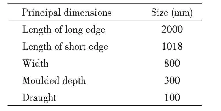
Tab.1 Principal dimensions of single module
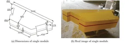
Fig.1 Single module of hexagon enclosed platform model
It is important to design a moderate rigid connector in this study. The RMRC connector needs to have moderate rigidity.On one hand,large deformation is not allowed because the connector is of RMRC model. On the other hand, it is necessary to retain micro-deformation for the connector be⁃cause strain sensors are arranged on connectors to measure the micro-strain so that the connector load can be transformed.Therefore,square flange and stainless steel pipe in which 4 holes are locat⁃ed in middle part is used to simulate RMRC connector in this test, the materials of connectors are 304 stainless steel. Four holes make the connector model have moderate micro-deformation so that the strain sensor is able to measure the micro-deformation which can be transformed to connector load.Two ends of the pipe are arranged with four flanges for fixing to the rigid platform models.The RMRC connector model is shown in Fig.2.Four strain sensors are arranged on the connector to mea⁃sure the micro-deformation of the connector in the test, the strain sensor arrangement on the con⁃nector is presented in Fig.3.
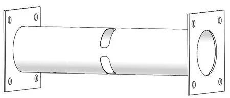
Fig.2 RMRC connector model
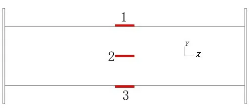
Fig.3 Strain sensor arrangement on connector

Fig.4 Rigid connector load measurement calibration
Calibration process of a rigid connector is performed to obtain the relationship of strain and section load of the connector before the test, an end of the connector is fixed, another end hangs a mass piece, then the strain sensors are tested, so the connector loads-strain relationship is ob⁃tained, Fig.4 shows the calibration principle of the rigid connector. Six trapezoidal fiber⁃glass modules and six connectors are connect⁃ed to make up the hexagon enclosed platform model as shown in Fig.5.
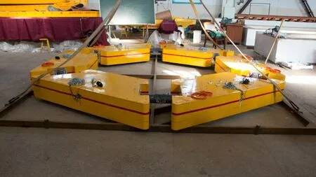
Fig.5 Hexagon enclosed platform model
1.2 Tank test
The tank test is performed in the large deep and shallow water model towing tank of Wuhan University of Technology. The principal dimen⁃sions of the towing tank is 132 m×10.8 m×2 m, and the water depth could be adjusted. The laboratory is equipped with a 24-unit wave maker, which can produce regular waves, two-dimensional constant peak irregular waves,three-dimensional directional waves and single waves conforming to extreme wave characteristics. The wave height range is from 0.01 m to 0.4 m. Fig.6 shows the large deep and shallow water model towing tank.
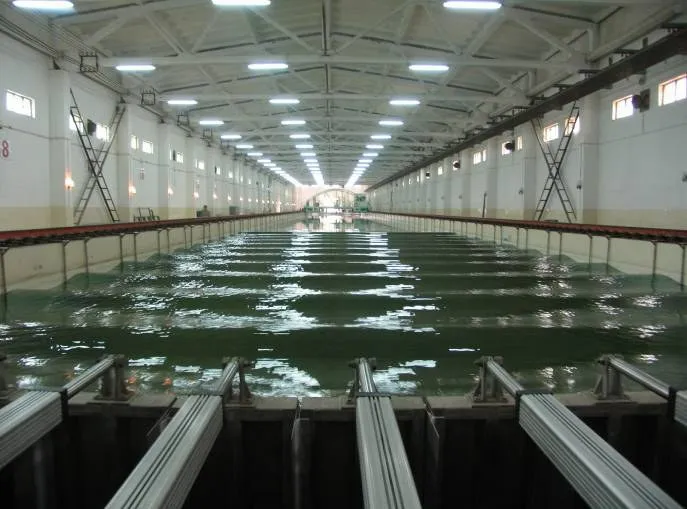
Fig.6 Large deep and shallow water model towing tank
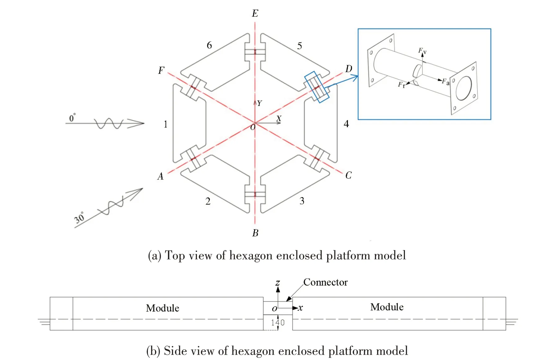
Fig.7 Hexagon enclosed platform model
The experimental model of the hexagon enclosed platform composed of six modules is put into the wave tank.Mass distribution is arranged to ensure draught balance.Each module is numbered from 1 to 6 and each connector is named fromAtoFas Fig.7 shows. Six slack mooring lines are used to restrain horizontal drift motion instead of vertical motion. The influence of wave length and wave height on connector loads is investigated. The con⁃nector load means section forces involving the vertical forceFv, the radial forceFrand the axial forceFaat SectionA-F,the vertical forceFvdenotes the force in depth direction,the radial forceFrimplies the force in direction pointing from connector to center of platform,the axial forceFameans the force along pipe axial direction.The schematic diagram of connector loads is showed in Fig.7(a).The platform model is moved to the center of the wave tank before the experiment is performed. In this experiment,a number of regular waves are made for the platform model,the connector can gen⁃erate recognizable strain,and then the strain is transformed to load levels.Modules 1 and 2 are clos⁃er to the wave maker, different heading wave angles are obtained by rotating the model. Wave an⁃gles of 0° and 30° are discussed in this paper. Two diagonal connectors can constitute a section.three sections (A-D,B-E,C-F) are defined and selected to study the section loads as shown in Fig.7(a).Fig.7(b)shows the side view of the hexagon enclosed platform model and the distance from the connector to the baseline.Fig.8 shows the hexagon enclosed platform model in the model test.

Fig.8 Hexagon enclosed platform model tank test
2 Basic Theory
In this study, a hydrodynamic solver Hydrostar is employed to calculate water pressure acting on VLFS model, then the loads of connectors are obtained. This solver employs 3D radiation-dif⁃fraction theory for hydrodynamic pressure calculation as follows:

whereυdenotes the wave number,υ=ω2/g,ωis the wave frequency,nis the wetted surface nor⁃mal vector,and i is the imaginary unit.
The potential theory assumptions were adopted for the hydrodynamic part of the problem.Within this theory the total velocity potentialφ, in the case of no forward speed, was defined with the Laplace differential equation and the given boundary values.
Linear wave theory enables the following decomposition of total potential:

whereφIrepresents the imputting wave potential,φDrepresents diffraction potention andφRjrepre⁃sents the radiation potential.
Body boundary condition of Eqs.(1)-(3)could be deduced for each potential.
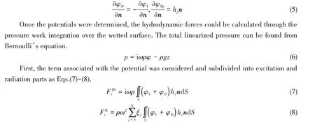
Thus, Eq.(7) represents the hydrodynamic pressure excitation. Now Eq.(8) can be decomposed into the modal inertia force and damping force associated with acceleration and velocity respective⁃ly.

whereAijandBijrefer to the added mass and damping matrices respectively. Determination of added mass and damping for rigid body motion is a well-known method⁃ology in ship hydrodynamics.
The hydrodynamic platform generates wetted sur⁃face mesh model, thereby achieving panels of more reg⁃ular shape and refined subdivision in the area of the free surface. The hydrodynamic panel mesh is shown in Fig.9. There are 45 894 meshes on the hydrodynamic model.In such a way,efficiency and accuracy of the hy⁃drodynamic calculation is ensured.
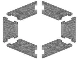
Fig.9 Hydrodynamic panel mesh
3 Comparison and analysis of load RAOs
3.1 Load RAOs at a wave angle of 0°
The results of test and simulation are organized in this paper to obtain the RAOs of the connec⁃tors,the load RAOs of test and calculation were compared and analyzed.This study presents RAOs ofFrandFaat wave angles of 0°and 30°.
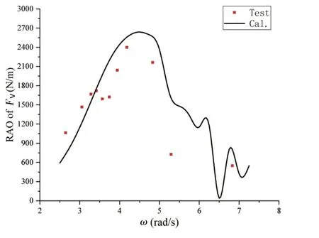
Fig.10 Fv RAOs of Section B-E(Wave angle:0°)
When the wave angle is equal to 0°,the platform module of No.1 is in heading waves as shown in Fig.7. In this case, SectionsA-F,B-EandC-Dmust have the same loads due to structural symmetry.ConnectorBand ConnectorEhave the same longitu⁃dinal section, SectionB-Ecan determine a merged transverse section. According to the results, SectionB-Ehas a significant vertical forceFvwhile the radi⁃al forceFrand the axial forceFaboth have rather neg⁃ligible values,it is shown from analysis that the longi⁃tudinal load is most significant while other forces are negligible in the case of the platform module of No.1 in heading waves. Fig.10 shows the load RAOs of SectionB-E. It can be seen from Fig.10 that SectionB-Ehas the maximum load when the encounter frequency is equal to 4.5 rad/s.
In this case, the diagonal section ofA-Dis analyzed to determine the connector load ofAandD. Axial force is negligible while radial force and vertical force are significant based on the results with regard to the diagonal section ofA-D. Fig.11 shows the radial loadFrof SectionA-Dand Fig.12 gives the vertical loadFvof SectionA-D.It is implied from Fig.11 that simulation curve has the maximum radial force when the frequency is equal to 5.25 rad/s.It is seen from Fig.12 that RAO ofFvhas the maximum value when the frequency is equal to 6.324 rad/s. The wet frequency of the platform model is solved by using a hydrodynamic solver HOMER. The 4th-6th frequencies are 4.852 rad/s, 5.413 rad/s and 6.508 rad/s respectively. The 1st, 2nd and 3rd frequencies reflect surge motion, sway motion and heave motion respectively while the 4th, 5th and 6th frequency re⁃flects roll motion, pitch motion and yaw motion respectively. It is seen from Fig.11 and Fig.12 that the maximum points appear at the wet frequencies.
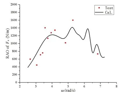
Fig.12 Fv RAOs of Section A-D(Wave angle:0°)
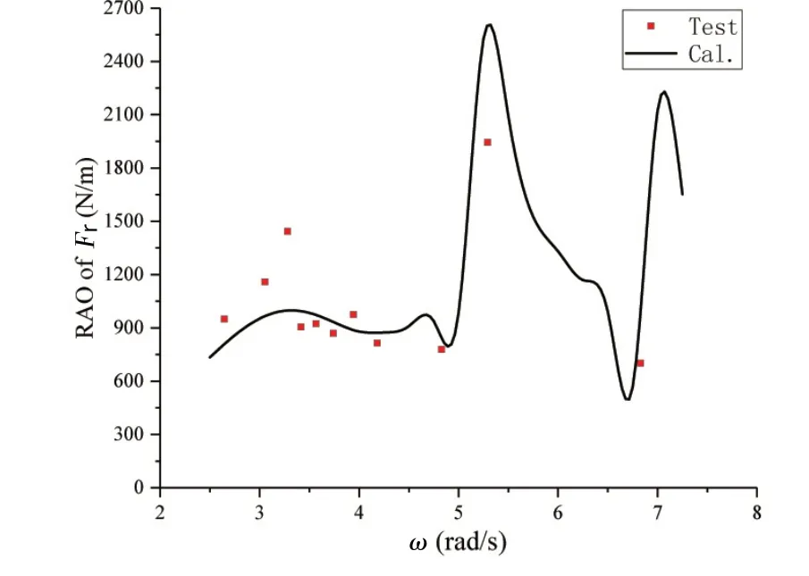
Fig.11 Fr RAOs of Section A-D(Wave angle:0°)
3.2 Load RAOs at a wave angle of 30°
The platform model is rotated 30°to make ConnectorAin heading waves.In this case,SectionA-Dbecomes a longitudinal center section,SectionsB-EandC-Fare both diagonal ones,and Sec⁃tionsB-EandC-Fare completely symmetrical so they must have similar load levels.Therefore,on⁃ly the results of SectionB-Eare discussed in this paper. Different waves are made for the platform model by changing the wave length and fixing the wave height to obtain the load RAOs of all the connectors. In this case, the axis force is small enough and only the radial force and vertical force are discussed in this paper. Fig.13 gives the radial force RAO of SectionB-Ewhile Fig.14 shows the vertical force RAO of SectionB-E.

Fig.13 Fr RAOs of Section B-E(Wave angle:30°)
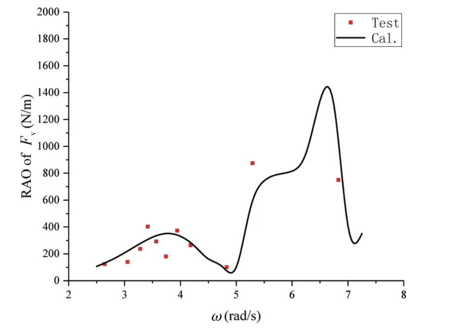
Fig.14 Fv RAOs of Section B-E(Wave angle:30°)
In this study,the number of the test cases is finite so that the test load RAOs just have discrete data points, the tests do not necessarily have to reach the maximum RAO value while simulation can obtain enough values so that simulation can give a smooth curve to obtain the maximum value.
3.3 Motions of hexagon enclosed platform model
Fig.15 and Fig.16 show the heave RAO and the pitch RAO respectively with the wave angle of 30°[24]. The experimental results are basically consistent with the overall trend of the calculated re⁃sults. It is seen from Fig.15 that the heave RAO has smaller values at the frequencies of 0.58 Hz and 0.88 Hz,and larger values at the frequencies of 0.74 Hz and 1.05 Hz.The extreme values of the heave RAO are close to the 4th-6th wet frequencies of the model.It is implied from Fig.16 that the pitch RAO has a maximum value at the frequency of 0.53 Hz when the wavelength is close to the to⁃tal length of the hexagon enclosed platform model. For general ships and ocean engineering struc⁃tures, the maximum vertical wave bending moment often occurs when the wave length is equal to the ship length,so the amplitude of pitch motion is also large.
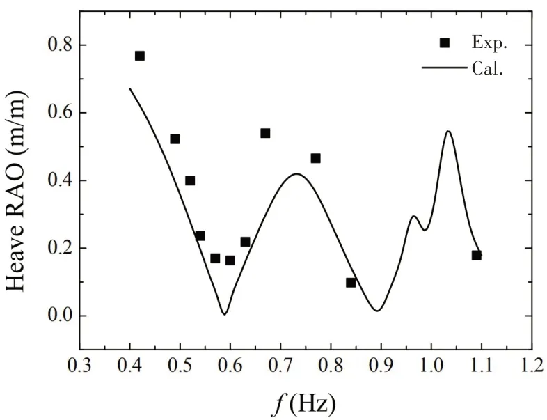
Fig.15 Heave RAO(Wave angle:30°)[24]
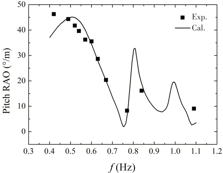
Fig.16 Pitch RAO(Wave angle:30°)[24]
4 Conclusions
In this paper, the load characteristics of a hexagon enclosed platform model are studied. Com⁃bining with model test and numerical simulation methods, the load characteristics of the rigid con⁃nector model in regular waves are obtained.Some conclusions are drawn as follows:
(1) The load RAOs of the hexagon enclosed platform model present multiple peak points, and the corresponding frequencies of the peak points are mostly around the 4th-6th wet modes of the test model.
(2) As the numerical simulation is conducted based on the three-dimensional potential flow theory without consideration of water viscosity, the peak value measured in the test is lower than that in the numerical simulation.
(3) On the whole, the experimental results are in good agreement with those of the numerical simulation,and the reliability of the numerical simulation approach is verified.The numerical simu⁃lation method proposed in this paper can be used as a reference for calculation of the profile load at the hexagon enclosed platform connectors.
The load characteristics of flexible connectors of hexagon enclosed platforms will be studied in future.
Acknowledgements
All authors gratefully acknowledge the fund support of National Science Foundation of China(No.52071243;52101371).
- 船舶力学的其它文章
- An Approach for Connector Arrangement of Very Large Floating Structures
- Structural Redundancy Verification for Side Shell Frame of Single Side Skin Bulk Carriers
- Dynamic Mechanical Behavior and Constitutive Relation of Shipbuilding E36 Steel
- Buckling Characteristics and Influencing Factors of Composite Grid Sandwich Plates with Soft Core
- Investigation on the Resistance of Planing Hulls Based on a New Mathematical Model
- Application of Computational Methods for Hydrodynamic Pressure Caused by Supercritical Ship in Shallow,Finite or Deep-depth Waters

