The Simultaneous Three-channel Multicolor CCD Photometric System of the 1.2 m Telescope at Jilin Astronomical Observatory*
Bing-Li Niu ,Cheng-Zhi Liu ,Zhen-Wei Li ,Zhe Kang ,and You Lv
1 Changchun Observatory,National Astronomical Observatories,University of Chinese Academy of Sciences,Changchun 130117,China;lcz@cho.ac.cn
2 University of the Chinese Academy of Sciences,Beijing 100049,China
Abstract We will introduce the construction and design of a new simultaneous three-channel multicolor CCD photometer.This photometer has been mounted on the 1.2 m telescope at Jilin Astronomical Observatory,and is applied to study space debris,gamma-ray burst afterglows,asteroids and other rapidly variable objects.As one of the ground follow-up telescopes of the Chinese-French Space-based multi-band astronomical Variable Objects Monitor(SVOM) mission,it appears very essential to evaluate the performance of the photometry system of this photometer,which can achieve simultaneous imaging within a field of view ofandin the Sloan Digital Sky Survey (SDSS) g′,r′,i′ bands,respectively.Photometric calibrations were carried out by using plenty of SDSS standard stars,and the relationship between the photometric system and the Johnson-Bessel filter system was also studied.The results of the performance evaluation from observing open cluster M67 are presented.
Key words:astronomical instrumentation– photometer– photoelectric photometry
1.Introduction
In recent years,multicolor CCD photometric technology has attracted great attention for its wide applications in astronomical observations including variable stars,active galactic nuclei and gamma-ray burst (GRB) afterglows (e.g.,Greiner et al.2008),so that the underlying mechanism and physical origin of the observed properties could be studied (Warner 2006).In addition,photometric measurements of fast-moving objects can determine their surface materials,shapes,rotations and internal structure.It can also be employed to monitor the operating state of space debris (Santoni et al.2013;Sun &Zhao 2013).Currently,the most used photometry system is based on the filter wheel,which changes the filter in turn to achieve photometry at different wave bands.However,it will introduce incorrect results when observing rapid variables and fast moving objects due to the rapid variation of brightness or color.In comparison with the traditional multicolor CCD photometry system,three-channel multicolor CCD photometry has advantages in making observations simultaneously in different filter bands,as well as with higher temporal resolution.This approach is especially suitable for measurements of shortperiod variables,GRBs (Greiner et al.2008) and space debris.
Nowadays,many countries have carried out simultaneous multicolor CCD photometry with different telescopes,such as the Chilean GROND-a 7-Channel imager which is installed on the MPI/ESO 2.2 m telescope (Greiner et al.2008) and ULTRACAM,which is a portable and high-speed imaging photometer(Dhillon et al.2007)that has been attached to both the 4.2 m William Herschel Telescope on La Palma and the 8.2 m Very Large Telescope in Chile.The Japanese Multicolor Imaging Telescopes for Survey and Monstrous Explosions(MITSuME) have been equipped on two 50 cm telescopes at Akeno and Okayama,respectively (Kotani et al.2005).However,in China there has been little research on the application of a multichannel photometer(Mao et al.2013).We always have strong motivation to do simultaneous multicolor CCD photometry for various variable objects in our observatory to promote the capability of astronomical observation in our country.In our work,a simultaneous three-channel multicolor CCD photometry system was designed and constructed utilizing the Sloan Digital Sky Survey (SDSS) g′,r′,and i′ bands,and was installed on the Cassegrain focus of the 1.2 m large-aperture telescope at Changchun Observatory,National Astronomical Observatories,Chinese Academy of Sciences,China.The 1.2 m telescope is also a member of the ground-based telescope in the Chinese-French Space-based multi-band astronomical Variable Objects Monitor (SVOM)mission,for GRB studies (Paul et al.2011),so it is of great significance to study the performance of this equipment.
We have characterized the photometry system of the photometer and results are reported in this paper.The telescope and site conditions are briefly introduced in Section 2.In Section 3,we describe the design and structure of the threechannel CCD photometer.The calibration and performance of the photometry system are reported in Section 4 and Section 5,respectively.Finally,we give our conclusion in Section 6.
2.The Telescope Parameters and Site Conditions
2.1.The Telescope Parameters
The 1.2 m telescope that belongs to Changchun Observatory of NAOC was designed and made by Shanghai Astronomical Observatory.A photograph and the optical path of the 1.2 m telescope are shown in Figures 1 and 2,respectively.The 1.2 m telescope has a reflective optical structure and two optical focus systems,one is a prime focus system and the other is a Cassegrain focus system.The switch between these two focus systems is realized by the secondary mirror controlled by a switching mechanism.The simultaneous three-channel multicolor CCD photometry system was installed in the Cassegrain focus system,so we will introduce the Cassegrain focus system in detail,and the performance of the prime focus system will be described in another paper.Both mirrors and mount characteristics of the 1.2 m telescope are listed in Table 1.The Cassegrain focus system was designed with a focal ratio of 8,and both primary and secondary mirrors of the 1.2 m telescope are hyperboloidal mirrors,with effective diameters of 1180 mm and 340mm,respectively,forming a spherical and coma aberration free Ritchey-Chrétien (R-C) optical system.Over the entire field of view (FOV),80% of the energy is concentrated within a 1″ point-spread function,and the transmittance of the optical system is better than 80%.The mount system is an equatorial fork mount with high accuracy friction servo motors.

Figure 1.The 1.2 m telescope.

Figure 2.The optical path of the telescope.

Figure 3.Monthly observational time in each month during the past four years.Left panel:numbers of monthly observational nights;Right panel:numbers of monthly observational hours.
2.2.The Site Conditions
The 1.2 m telescope is located at Xiaosuihe Village in Jilin City (126°20′24″ East,43°49′48″ North),with an elevation of about 313 m.We measured the seeing of Jilin Astronomical Observatory by using a differential image motion monitor(DIMM) with the help of Yunnan Observatory.The average value of seeing is aboutand the best value is better thanThe number of clear nights was achieved by using data recorded during the past four years from January 2017 to December 2020 as depicted in Figure 3.The observational time of the past four years was obtained according to the observation log of our Mini Optoelectronic Telescope Array.The left panel of Figure 3 displays the number of nights when observations were taken in each month.Meanwhile,the number of hours when the telescope was being operated during each month is shown in the right panel of Figure 3.As can be seen from Figure 3,during the summer time from June to August,the number of observation nights was minimum each year due to rainy and cloudy weather.In winter,it is necessary to defrost and maintain the dome due to extremely low temperatures,so actually there are more clear nights from November to January of the following year.As the plots demonstrate,during the past four years the number of observation nights in each year ranges from 165 to 223 with an average of 189 nights,and the number of observation hours per year ranges from 1599 hr to 2179 hr with an average of 1856 hr.
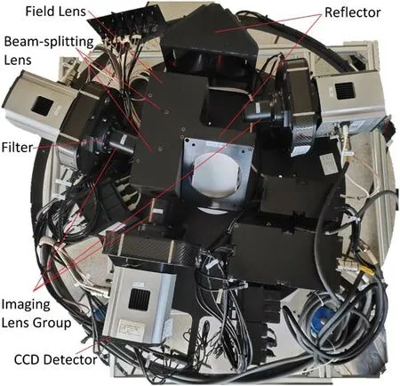
Figure 4.Photograph of the three-channel CCD photometer.
3.Parameters of the Three-Channel CCD Photometer
There are many ways to achieve multi-channel imaging simultaneously,such as by using a Philips prism (Berquist &Berquist 1996) or spectroscopic lens.A Simultaneous Photometer for Infrared and Visual light (SPIV),which was constructed by the Steward Observatory Mirror Lab of the University of Arizona,adopts the method of using a spectroscopic lens to achieve simultaneous photometry (Eisendart 1984).There are many advantages of this method,such as simple structure,easy assembly,lower polarization effect and accuracy of components that are easy to guarantee.In addition,it is easier to make the device with a larger size.In order to obtain a larger FOV of about 21′×21′,we adopt a spectroscopic lens to design the simultaneous three-channel multicolor CCD photometer.
3.1.Physical Structure
The structure of a three-channel CCD photometer is depicted in Figure 4.

Figure 5.Optical structure of the three-channel photometer.

Figure 6.Transmission of the u′ g′ r′ i′ z′ filters (Fukugita et al.1996).
1.Reflector:this part is composed of three mirrors including M3,M4 and M5 to ensure the alignment between the photometer and the main optical path because of the long focal length of the Cassegrain focus system.Each mirror has three degrees of freedom adjustment,which are pitch,azimuth and optical axis translation for the convenience of installation and alignment.
2.Field lens:this mirror is located between M5 and the first dichroic lens to collimate the light reflected by M5.
3.Beam-splitting lens:as the core of the three-channel CCD photometer,this part consists of two dichroic lenses that require special coating (Eisendart 1984) to achieve separation of the three color beams.
4.Imaging lens group:in order to optimize the beam quality,three lens groups were designed to correct the light path for three channels,respectively.
5.Filters:the light in the specified band is obtained after filtering by the filter,which is used for imaging in three channels.
6.CCD detectors:each channel is equipped with the same CCD camera,which is an Andor iKon-L DZ936N-BV,as an imaging terminal.
3.2.Optical System
The optical structure of the three-channel CCD photometer is illustrated in Figure 5.The optical wave bands chosen for the three channels are the g′,r′ and i′ bands of the SDSS system(Figure 6),respectively.The bandpasses of the SDSS filter system are wider than those of the Johnson/Bessel filter system,which is more suitable for faint object detection(Fukugita et al.1996).
To obtain a larger FOV,the three bands of g′,r′ and i′ are separated by using a beam-splitting lens,which divides the light collimated by the field lens into three beams for each channel.The first dichroic lens reflects the g′band beam,while the r′ band beam and the i′ band beam pass through,and the second dichroic lens reflects the r′ band beam and transmits the i′band beam.After filtering by the corresponding filter,the beams of each band enter the CCD detector to complete the operation of photometry and photometric measurement.Many factors are taken into account to evaluate the image quality,including FOV,degradations,full width at half maximum(FWHM),ellipticity,Moffat β and asymmetry.The results are shown in Figures 7,8 and Table 2.
3.3.CCD Detectors
The three-channel CCD photometer is equipped with three uniform detectors,which are backside illuminated.Parameters of the detector including readout noise,pixel size,quantum efficiency (QE),dark current and chip scale are under consideration,and the specifications of the CCD camera are listed in Table 3.Due to differences on the chip,the stability of bias,dark current and linearity of the CCD camera in each channel was tested,as displayed in Figures 9,10 and 11,respectively.In addition,the test results are plotted in Table 4.The QE curve of iKon-L DZ936N-BV is depicted in Figure 12,and the specific parameters of each channel are listed in Table 5.

Table 5 Parameters of three Channels

Table 6 Atmospheric Extinction Coefficients and Sky Brightness at Jilin Astronomical Observatory

Figure 11.The linear response curve of the iKon-L DZ936N-BV with scan rate of 1 MHz and gain 1×.

Figure 12.QE curve of iKon-L DZ936N-BV.

Table 4 Test Results of the CCD Detectors
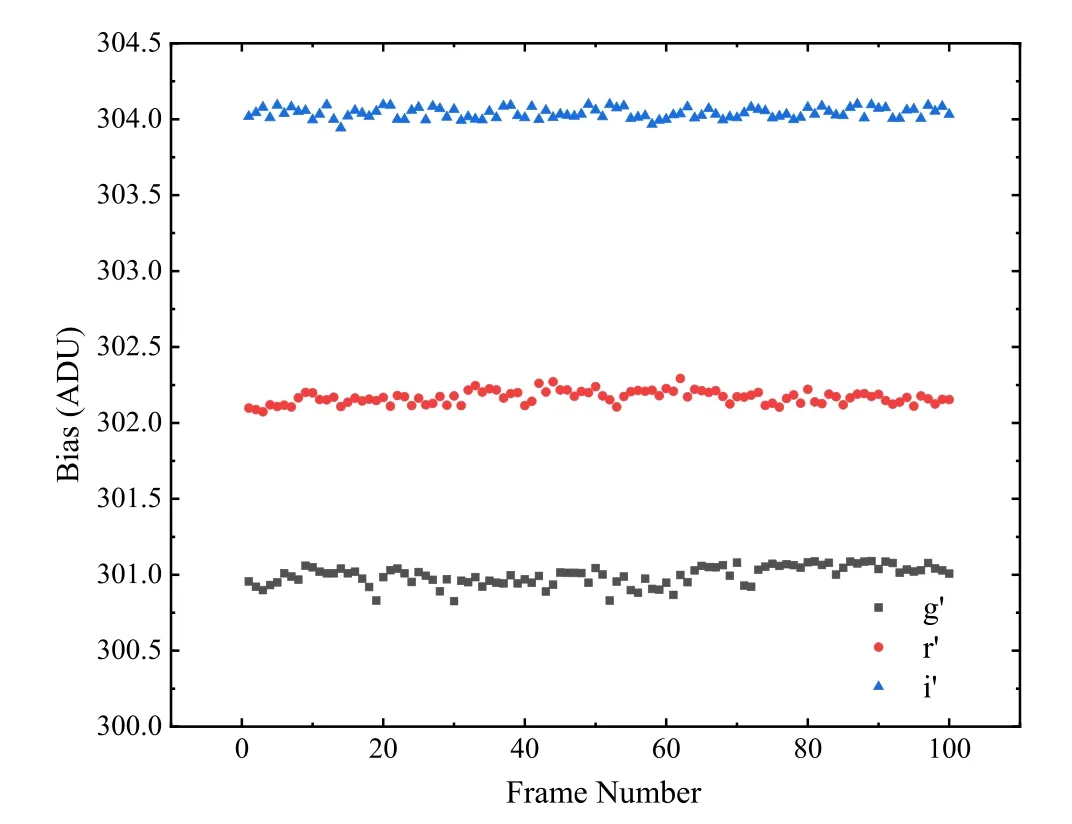
Figure 9.The stability of 100 bias frames from the iKon-L DZ936N-BV at a temperature of -70°C,with scan rate of 1 MHz.
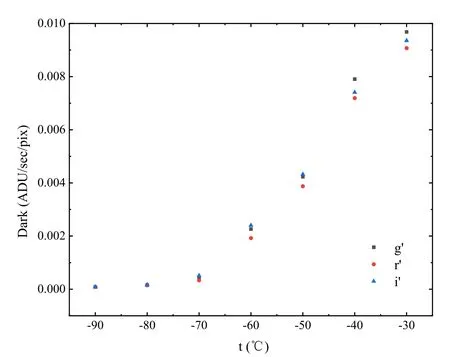
Figure 10.The dark current of iKon-L DZ936N-BV varies with different temperature with scan rate of 1 MHz and gain 1×.

Table 2 The Results of Image Quality Evaluation

Table 3 Specifications of the CCD Camera

Figure 7.Original images of open cluster M67 in the g′,r′and i′bands.Top left panel:the original image of the g′channel,with an FOV of 215×215;top right panel:the original image of the r′channel,with an FOV of 215×215;bottom panel:the original image of the i′channel,with an FOV of 213×213.The design of the optical path leads to the FOV of i′ band being different from the other two bands.

Figure 8.Degradations in optical quality along the off angle direction in the three channels.The result shows that the degradations in optical quality caused by aberrations and the possible CCD tilt are within 9%,which would be a side effect of large FOV.The star distortion at the edge of the FOV is inevitable,so we pay more attention to the image quality at the center of the FOV.
3.4.Software
The software system of the three-channel CCD photometer consists of three parts:observation support system,data acquisition system and data processing system.Each system communicates with each other through a socket based on TCP/IP(Ge et al.2015).The three cameras of each channel are controlled by three industrial personal computers,which can independently control the camera in this band for acquisition.The whole system runs in the Linux environment,and the three-channel camera is controlled by command for acquisition.In the Windows environment,the simultaneous acquisition of three-channel CCD cameras can be carried out manually.
1.The observation support system mainly provides a unified and high-precision time reference to the data acquisition and processing system through the time latch.The telescope control software and CCD camera control software adopt the on-demand synchronization mode,while the observation control service software and data processing software adopt the timing synchronization mode to realize the simultaneous observation of the three channel cameras.
2.The data acquisition system includes trigger source,client,control server and the computer that controls the telescope,as well as three industrial personal computers that control the CCD camera.The software that controls the CCD camera in each channel runs on the Linux platform,and integrates the terminal racer,focusing and auto focusing functions.The system can realize tracking observation and data acquisition flow of space fragments,conventional astronomical targets and emergencies.
3.The data processing system runs on the Linux platform,and the core algorithm of photometry is based on astronomical tools including Source Extractor (SExtractor,Bertin &Arnouts 1996),Astrometry-net (Lang et al.2010) and Astronomy in Python (AstroPy,Astropy Collaboration et al.2013).
4.System Calibration
The three-channel CCD photometer was installed on the 1.2 m telescope on 2020 September 26.In order to checkwhether the optical path of the three-channel CCD photometer was smooth or not after assembly,laser beams were used to test the overall optical path.The actual imaging operation was then performed and the mechanical focusing was carried out to ensure the imaging was displayed in the center of the FOV in each channel.
The system was calibrated during four observing runs taken in December of 2020,and March,April and November of 2021,respectively.This work was achieved by observing plenty of SDSS standard stars and Landolt standard stars which vary in magnitude and color,covering a wide sky region.The observation night was a standard photometric night,which was clear and moonless with a stable atmosphere.The calibration process includes the determination of the photometric zero-points for the three bands,system efficiency,field curvature and parfocality.
4.1.System Efficiency
The three-channel CCD photometer is an independent product with adjustment devices that can ensure the photometer is directly mounted on the telescope for imaging.In order to guarantee highefficiency of the three-channel CCD photometer,the system efficiency is taken into account in the design of its optical system,overall structure layout and electronic control communication system,so as to optimize the position of each mirror.In order to maximize the ability of the three-channel CCD photometer,each channel of the photometer is equipped with the same type of CCD camera as the imaging terminal.
The method of calculating system efficiency has been introduced in detail by Mao et al.(2013),which is adopted in our work to evaluate the efficiency of the three-channel CCDphotometer.By observing BD+750325 (airmass=1.2)during the system’s calibration,we calculate the efficiency of the three-channel CCD photometer.The result shows that the efficiencies of the g′,r′,i′ channels are 65.6%,68.3% and 63.7%,respectively.Considering the machining error of components and the overall assembly error of the three-channel CCD photometer,the efficiency fully meets the expectation.
4.2.Limiting Magnitudes
By observing Vega (α Lyr) at different airmasses,we determined the photometric zero-points of each band.The zeropoints of the g′,r′ and i′ bands are 23.49,22.85 and 21.97,respectively,as affirmed in Figure 13.Meanwhile,the atmospheric extinction coefficients in the g′,r′and i′bands together with night sky brightness (Zhang et al.2013) at Jilin Astronomical Observatory were measured,as listed in Table 6.Based on the measured zero-points,signal-to-noise ratio(SNR)and extinction coefficient,we calculate the limiting magnitudes of the g′,r′and i′ bands,which were 15.26,16.39,15.63,respectively (1 s exposure time and SNR=5).

Table 7 The Parameters of M67 member stars observed on 2021 November 27
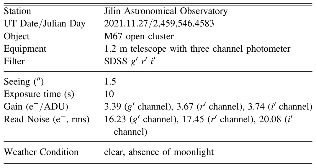
Table 8 Observing Log of M67
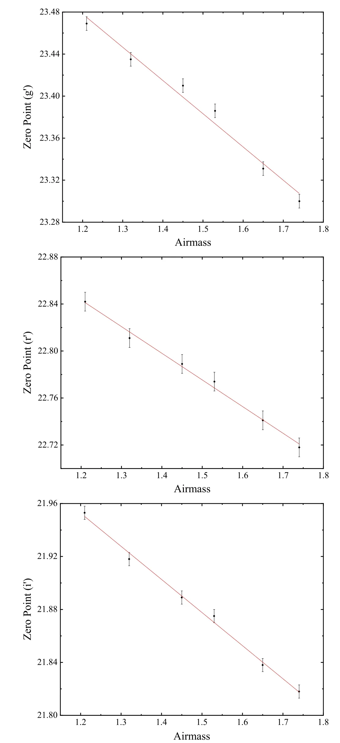
Figure 13.Zero-points in the g′,r′and i′bands.The photometric zero-points of each band are based on flux from a 1 s exposure of Vega (α Lyr) at different airmasses.Top panel:g′ channel;middle panel:r′ channel;bottom panel:i′channel.
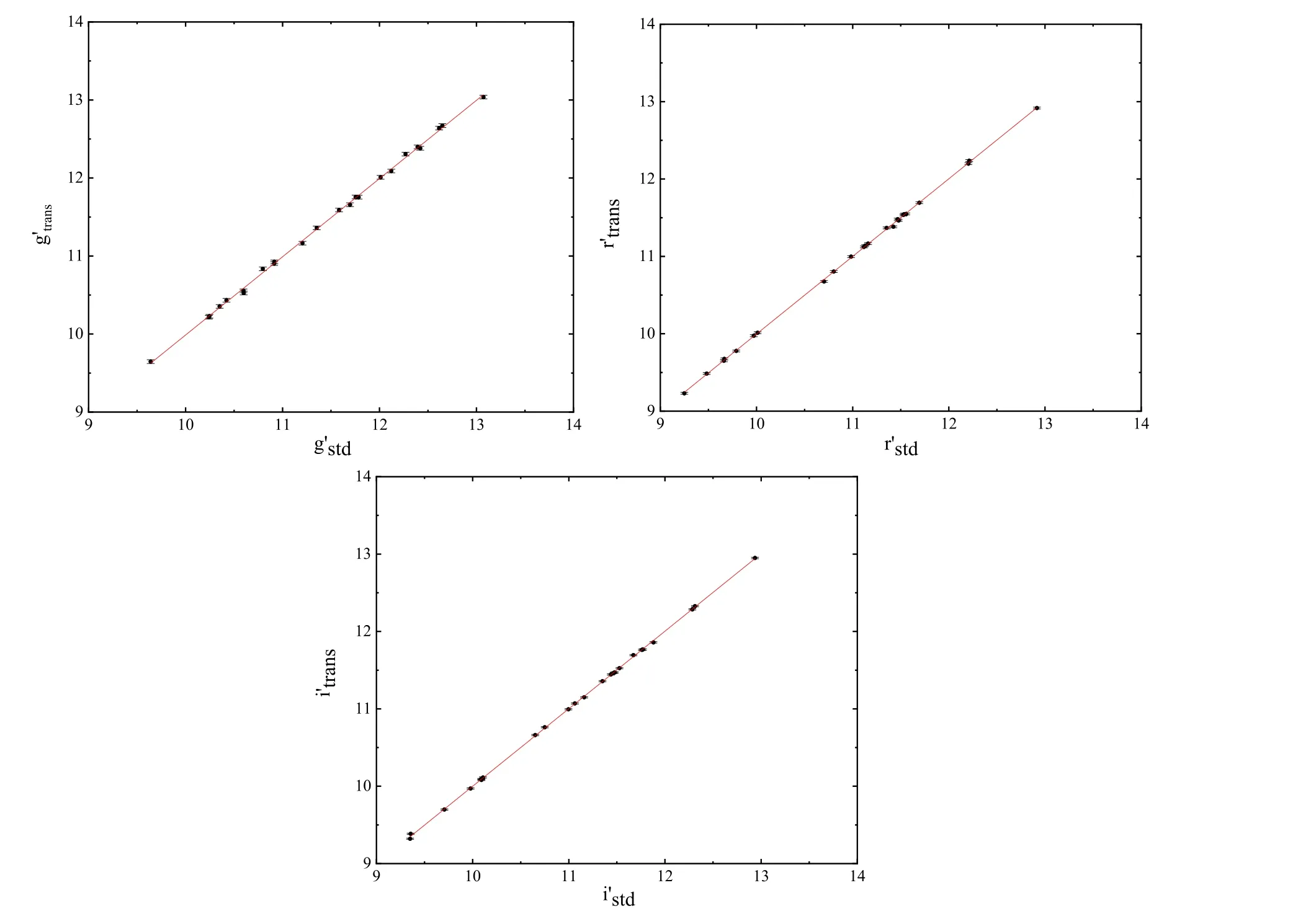
Figure 14.The relationship between standard magnitude (x) and transformed magnitude (y) is calculated by using transformation equations.Top left panel:g′channel;top right panel:r′ channel;bottom panel:i′ channel.
4.3.Photometric System Transformations
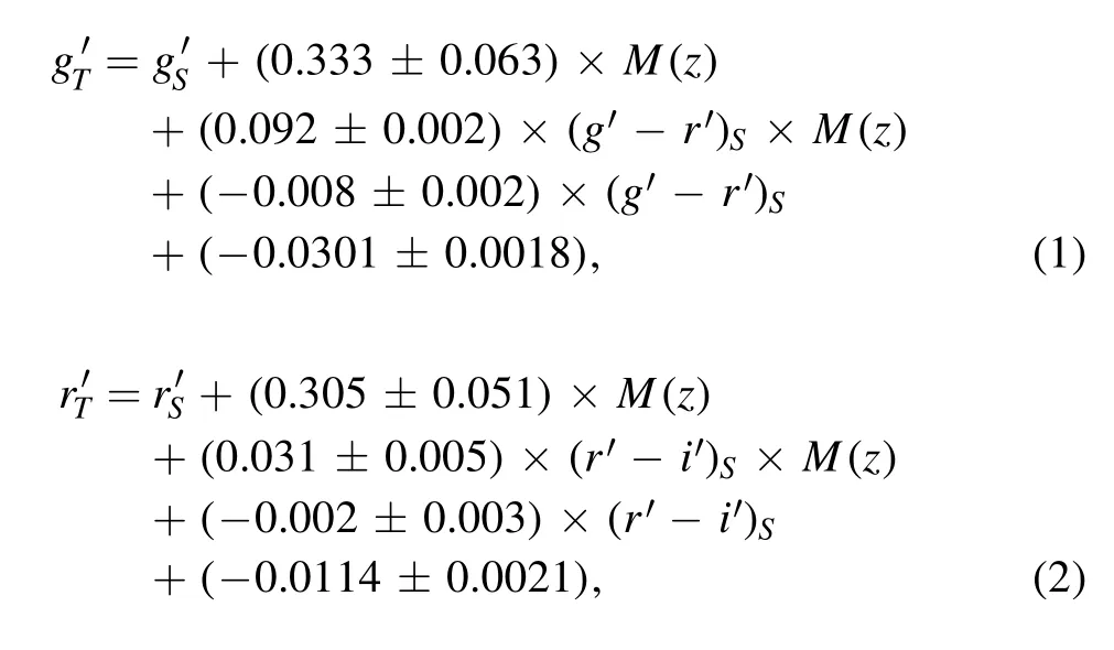
To make the system transformation results more reliable,we observed various types of SDSS standard stars.Meanwhile,a wide range of airmass and high SNRs were considered.The calibrated observations were carried out under standard photometric nights on 2020 December 6,2021 March 24,2021 April 26 and 2021 November 25.A number of standard stars were observed,and the position,magnitude and color index of the objects were taken into account.The transformation accuracies from the three-channel photometer system (T)to the SDSS standard system(S)are 2.9%in g′band,2.4%in r′band and 3.1% in i′ band,which are indicated by Figure 14,and the transformation equations are listed as follows(November 25):
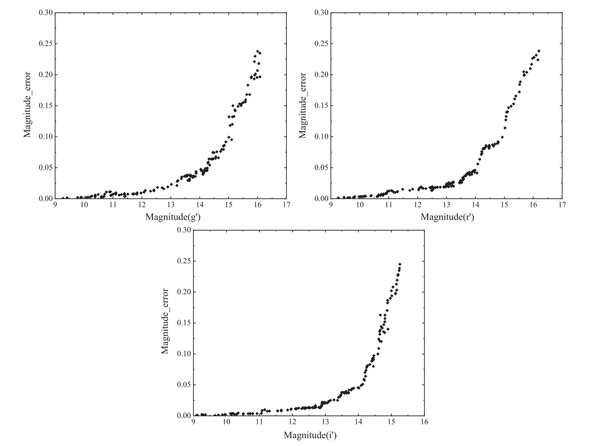
Figure 15.The photometric errors of standard stars with different magnitudes(exposure time=10 s,airmass=1.131).Top left panel:g′channel;top right panel:r′channel;bottom panel:i′ channel.
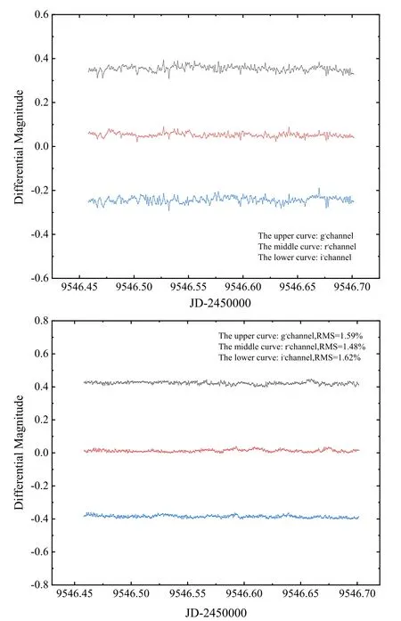
Figure 16.Differential photometric results of M67.Top panel:light curves of EX Cnc in three bands;bottom panel:light curves of the comparison star relative to the check star.There is a constant shift in the y-direction in order to optimize the visibility of light curves in the two panels.

Figure 17.The distribution of photometric error of M67 member stars.

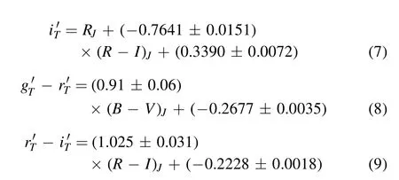
The relationship between the three-channel photometer system(T)and the Johnson-Bessel filter system (J)are studied by observing a number of Landolt standard stars (Landolt 1992,2013).Transformation equations are listed as follows(November 25):

The photometric accuracy was evaluated by observing abundant standard stars in SDSS and clusters (M67,Czernik 43).The photometric precision of the system in 9–14 mag is better than 4.3%in g′band and r′band,and 4.7%in i′band,as shown in Figure 15.We also calculated the primary and secondary extinction coefficients,and the sky brightness of Jilin Astronomical Observatory,as displayed in Table 6.The determination of the atmospheric extinction coefficient and the sky brightness takes a long time.Similarly,the system transformation from the three-channel photometer system to SDSS filter system is also a long-term work.In the future,we will improve the method for more comprehensive and systematic measurement,and the results will be described in another paper.
5.Performance of the Three Channel CCD Photometer
The simultaneous three-channel photometer is operated in Jilin Astronomical Observatory at present.As one of the ground-assisting telescopes of the SVOM project,it is of great significance to evaluate the performance of the photometer.In this paper,M67 (also known as Messier 67 or NGC 2682,hereinafter referred to as M67) is selected as the observation object,which is an open star cluster located in the constellation of Cancer,with about 500 members (Zhang et al.2005;Pribulla et al.2008;Peng et al.2016;Canton et al.2021).The star field is not dense and the brightness is concentrated in 10–11 mag,which is an ideal photometric calibration area.Our photometric work was performed in this cluster using a photometric standard catalog provided by the American Association of Variable Star Observers (AAVSO) [https://www.aavso.org].
EX Cnc is a blue straggler with δ Scuti-like variability in the solar-age Galactic open cluster M67 (Zhang et al.2005;Yakut et al.2009),whose period of light variation is 0.04852 days.The variable stars in the open cluster M67 were measured by using the method of differential photometry,according to the following principles:the comparison star and variable star are close in position,brightness and color,so that six standard stars in the cluster were selected as comparisons for eliminating the effects of atmospheric extinction.In addition,the calibration stars were calibrated by six check stars.We conducted overnight tracking observations of the open clusters,and detailed information about the observed objects and observing log of M67 are provided in Tables 7 and 8,respectively.
The magnitudes of the comparison stars are stable as affirmed in Figure 16,thus it is feasible to use these six stars to evaluate the photometric accuracy and differential magnitudes of EX Cnc.In addition,by calculating the rms of the differential magnitudes between the comparison stars and check stars,we find that the photometric accuracies of the g′,r′and i′ bands are 1.59%,1.48% and 1.62%,respectively.In order to study the distribution of the photometric error,135 member stars of M67 ranging from 10 mag to 16 mag were selected,as depicted in Figure 17.
The photometric error of most M67 member stars is better than 0.1 mag,indicating that the three-channel CCD photometer has good stability and reliability.There is good coordination and consistency in the work,as a result of the same type of camera.The photometric error of faint stars is relatively large due to the limiting magnitude of each channel,which could be improved by appropriately increasing the exposure time while ensuring a higher SNR.The variation of photometric error with the magnitude of the standard star can be suggested by Figure 15.The results fully meet the expectations and work demands,considering the inevitable machining and assembly errors of the parts of the three-channel CCD photometer.
6.Summary
The multicolor CCD photometer installed in Jilin Astronomical Observatory is a three-channel simultaneous photometer with an FOV ofin the SDSS g′,r′,i′bands,respectively.The efficiency of each band is 65.6%,63.7%and 68.3%,respectively.The limiting magnitudes of the g′,r′,i′ bands are 15.46,16.89 and 15.93,and the accuracy of differential photometry of each band in terms of rms is 1.59%,1.48%and 1.62%,respectively.In the future,we will upgrade the system software to do the data processing after receiving the images generated by the CCD camera so as to improve the work efficiency.Moreover,we will try to optimize the image quality of the edge FOV to make good use of the photometer for observation tasks,expecting better performance.
Acknowledgments
This work is a part of research done by the Astronomical Joint Fund of the National Natural Science Foundation of China (NSFC,Grant No.U2031129),together with the Youth Innovation Promotion Association of the Chinese Academy of Sciences (2018079),and Project of the National Center for Astronomy,Chinese Academy of Sciences (2019).
Thanks go to Xiaomeng Lu and Chao Wu at National Astronomical Observatories for their help in this project,and also to Bowen Li,Guangsheng Zhang and Chunlei Guo at Jilin Astronomical Observatory for their hard work.
 Research in Astronomy and Astrophysics2022年5期
- Research in Astronomy and Astrophysics的其它文章
- Discovery of Extended Structure Around Open Cluster COIN-Gaia 13 Based on Gaia EDR3
- Constraining Brans-Dicke Cosmology with the CSST Galaxy Clustering Spectroscopic Survey
- The First Photometric Study of AH Mic Contact Binary System
- Detections of Gamma-Rays from Globular Clusters ESO 452-SC11,NGC 6380,Palomar 6 and UKS 1 with Fermi-LAT
- Crust Cooling of Soft X-Ray Transients-the Uncertainties of Shallow Heating
- Quasi-periodic Oscillation Analysis for the BL Lacertae Object 1823+568
