Viability of Harvesting Salinity Gradient (Blue) Energy by Nanopore-Based Osmotic Power Generation
Zhangxin Wang, Li Wang, Menahem Elimeleh,*
a Institute of Environmental and Ecological Engineering, Guangdong University of Technology, Guangzhou 510006, China
b Southern Marine Science and Engineering Guangdong Laboratory (Guangzhou), Guangzhou 511458, China
c Department of Chemical and Environmental Engineering, Yale University, New Haven, CT 06511, USA
Keywords:Nanopore power generator Salinity gradient (blue) energy Power density Specific extractable energy
ABSTRACT The development of novel materials with ion-selective nanochannels has introduced a new technology for harvesting salinity gradient (blue) energy, namely nanopore power generators (NPGs). In this study,we perform a comprehensive analysis of the practical performance of NPG in both coupon-size and module-scale operations. We show that although NPG membrane coupons can theoretically generate ultrahigh power density under ideal conditions, the resulting power density in practical operations at a coupon scale can hardly reach 10 W·m-2 due to concentration polarization effects. For module-scale NPG operation, we estimate both the power density and specific extractable energy (i.e., extractable energy normalized by the total volume of the working solutions), and elucidate the impact of operating conditions on these two metrics based on the interplay between concentration polarization and extent of mixing of the high- and low-concentration solutions. Further, we develop a modeling framework to assess the viability of an NPG system. Our results demonstrate that, for NPG systems working with seawater and river water, the gross specific extractable energy by the NPG system is very low(~0.1 kW·h·m-3) and is further compromised by the parasitic energy consumptions in the system(notably, pumping of the seawater and river water solutions and their pretreatment). Overall, NPG systems produce very low net specific extractable energy (<0.025 kW·h·m-3) and net power density(<0.1 W·m-2).Our study highlights the significant practical limitations in NPG operations,casting doubt on the viability of NPG as a technology for blue energy harvesting.
1. Introduction
To meet the rapidly growing global energy demand and mitigate the environmental impact of burning fossil fuels,it is crucial to produce sustainable energy using alternative sources [1,2].In the past decades, salinity gradient energy, also commonly referred to as blue energy, has been extensively explored as a potentially promising energy source [3-6]. Such blue energy is essentially the free energy released from the mixing of two solutions with different salinities (e.g., seawater and river water).Based on simple estimations, the theoretical global power of mixing seawater and river water can reach 2 TW of electricity,which is approximately 10%of the current global energy consumption[5,7].
Several engineered systems have been developed to harvest blue energy [8]. The system that has been investigated the most,to date, is pressure retarded osmosis (PRO), which converts blue energy first to mechanical work using a semipermeable membrane and then to electric energy using a hydro-turbine [1,9]. Another system that has been well investigated is reverse electrodialysis(RED),in which electricity is directly generated from salinity gradients with ion-exchange membranes[10,11]. However,to date, the practical implementation of PRO and RED has been limited,mainly due to the low power density at a practical system scale beyond the commonly studied laboratory, coupon-scale membranes [8].The power density (PD) of the first full-scale PRO plant was about 3 W·m-2, achieved by mixing seawater and river water [12]; a pilot-scale RED plant working with concentrated brine and brackish water achieved a power density of only 1.6 W·m-2[13].Importantly,besides the low power density,the viability of PRO and RED has also been questioned as the extractable energy is generally low and would be significantly compromised by the parasitic energy consumptions in practical operations [1,8,9].
Recently,novel materials with ion-selective nanochannels have been proposed to harvest blue energy [14,15]. These materials,often referred to as nanopore power generators (NPGs), have demonstrated ultrahigh power densities for a single nanopore,potentially overcoming the limitation of low power density in PRO and RED operations[16-23].For example,based on the results from single-nanopore experiments,it was speculated that a power density of 4 kW·m-2could be achieved with a boron nitride nanotube-based NPG with high- and low-salinity solutions of 1000 and 1 mmol·L-1, respectively [16]. Similarly, another study claimed that an ultrahigh power density of 106W·m-2could be obtained with an NPG made of single-layer molybdenum disulfide with high- and low-salinity solutions of 1000 and 1 mmol·L-1,respectively[17].Lastly,in a very recent study,a single-layer nanoporous membrane coupon was fabricated from core-rim polycyclic aromatic hydrocarbon,offering a power density of 67 W·m-2with seawater and river water solutions [19].
However, so far, all the studies on NPG have been limited to bench-scale experiments with single nanopores or small membrane coupons under ideal experimental conditions. In practical applications, the performance of coupon-size NPG is substantially affected by realistic operating conditions,such as the hydrodynamics and electric resistance of the solutions. Furthermore, like PRO and RED, the successful demonstration of coupon-size NPG operation does not guarantee viable practical implementation of a largescale NPG system because the energy consumption required for operation (e.g., pretreatment of the working solutions and frictional losses in the NPG module) might outweigh the energy produced from the system. To evaluate the practical viability of large-scale NPG systems, the performance of module-scale NPG with realistic operating conditions and constraints must be investigated. Furthermore, it is imperative to analyze the extractable energy efficiency of a full-scale system under practical operating conditions.
In this study, we systematically assess the practical viability of NPG in harvesting blue energy from salinity gradients. Both coupon-size and module-scale NPG operations are thoroughly investigated. The coupon-size NPG analysis demonstrates that power density, the most relevant performance metric at the coupon scale, is limited by concentration polarization (CP) regardless of membrane material properties. In module-scale analysis, in addition to power density, the specific extractable energy (SEE)(i.e., the energy output normalized by the total volume of the working solutions) is another important performance metric. We investigate the impact of operating conditions on both the power density and specific extractable energy of module-scale NPG operation under realistic operating conditions.We further show that in practical operation, the NPG net specific extractable energy is significantly reduced due to parasitic energy consumption by pretreatment and pumping. We conclude by highlighting the daunting challenges to implement NPG in practice and the overall viability of the technology.
2. Working principle of NPG
The working principle of a typical NPG system is shown in Fig.1[14].Specifically,an NPG membrane is used to separate two working solutions with different salinities.Because the nanopores in the NPG membrane are charged, counter-ions preferentially transport through the membrane over co-ions from the high-salinity to the low-salinity side of the membrane. The selective transport of ions results in the development of a potential difference across the NPG membrane, ΔE, which can be estimated by the Nernst equation[4,24]:
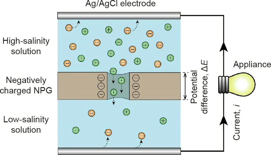
Fig.1. Schematic of NPG operation.A negatively charged NPG is used to separate a high-salinity solution and a low-salinity solution.Cations(green spheres)transport through the NPG under a concentration gradient, while the transport of the anions(orange spheres) through the negatively charged pores is limited. An electric potential difference across the NPG,ΔE, is developed due to the selective transport of cations over anions. By placing two Ag/AgCl reference electrodes on each side of the NPG, a closed electrical circuit can be obtained, and electric current, i, is generated via redox reactions on the reference electrodes.

where S is the ion selectivity defined as the difference between the cation and anion transference numbers(S=0 for no ion selectivity and S=1 for perfect ion selectivity), Rgis the gas constant, T is the absolute temperature,z is the ion valence,F is the Faraday constant,and cH,mand cL,mare the membrane surface concentrations on the high-salinity and low-salinity sides, respectively.
To harvest blue energy from selective ion transport across the NPG membrane, a pair of reference Ag/AgCl electrodes is employed. The redox reactions of the Ag/AgCl electrode not only convert the selective ion transport to current, but also maintain electroneutrality in the solutions. Using the generated current to drive an electrical load, blue energy is successfully harvested in the system. We note that, in addition to Ag/AgCl electrodes, electrodes with other reversible redox couples (e.g., Fe2+/Fe3+), like in RED, can be used for NPG operation as well [5,25].
3. Performance of coupon-size NPG
3.1. Maximum power density of NPG under ideal experimental conditions
In most NPG studies, experiments are conducted with small NPG coupons and complete mixing in each solution. In such scenarios, the maximum power density, PDmax, can be calculated as

Based on Eq. (2), for given high-salinity and low-salinity solution concentrations, PDmaxof NPG can be enhanced by improving the ion selectivity and ion conductance of the NPG membrane.This conclusion has been proved in a variety of studies in which ion selectivity and ion conductance of the NPG membrane were significantly improved by tuning the material properties (e.g., nanopore size,membrane thickness,and surface functional groups),resulting in a substantially enhanced PDmax[16,17,22,26,27]. However, we emphasize that Eq. (2) holds only for the scenarios of complete mixing in each solution, and such scenarios can only be approached in bench-scale and coupon-scale NPG experiments.
3.2.Impact of membrane properties on maximum power density in the presence of concentration polarization
InpracticalNPGapplications,thesolutionsneedtobereplenished by continuously flowing fresh solutions through the system,resulting in boundary layers on the membrane surface.The different ion mobilities in the solution and NPG membrane lead to concentration gradients across the boundary layers(Fig.2(a)),namely concentration polarization [28-31]. Because concentration polarization determines the membrane surface concentrations, it affects the potential difference across the NPG,ΔE(Eq.(1)),and thereby has a significant impact on the PDmaxof the NPG operation(Eq.(2)).
To quantify the impact of concentration polarization, an equivalent circuit of a practical NPG operation is shown in Fig. 2(b),where concentration polarization effects can be treated as an electrical resistance originating from the boundary layers, rBL.Based on Figs. 2(a) and (b), the current density, i, in an NPG operation with concentration polarization, can be obtained as

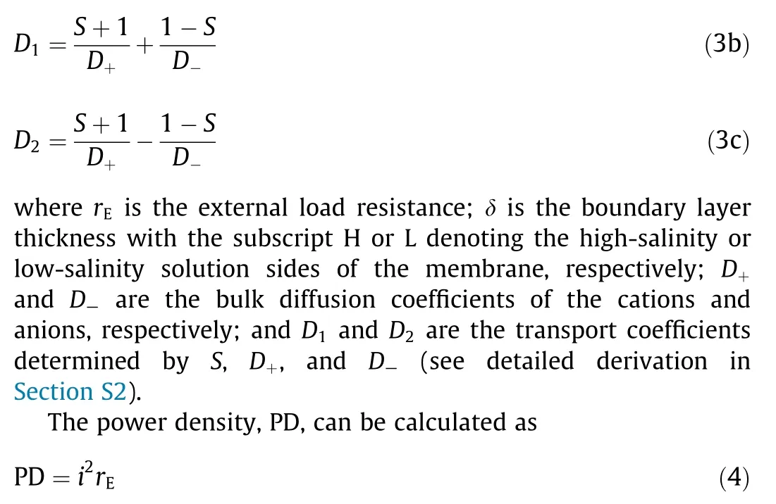
For given high-salinity and low-salinity solution concentrations, the PDmaxas well as the corresponding rBLcan be obtained based on Eqs. (3) and (4) (see detailed derivation in Section S2).
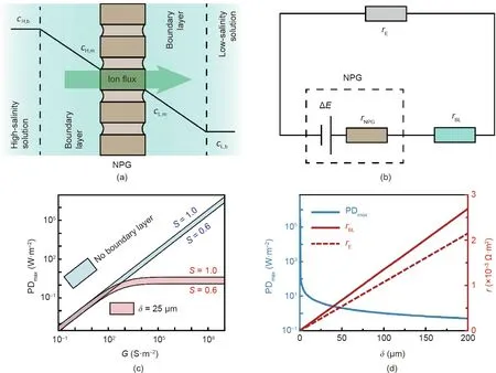
Fig. 2. Impact of concentration polarization on the maximum power density of an NPG membrane, PDmax. (a) A schematic of concentration polarization across an NPG membrane. (b) Equivalent circuit of an NPG system. ΔE denotes the potential difference across the NPG membrane; rNPG, rBL, and rE represent the resistances of the NPG membrane, boundary layers, and external load resistor, respectively. (c) PDmax as a function of membrane ion conductance, G, without (blue region) and with (red region)concentration polarization.In each region,the membrane ion selectivity,S,ranges from 0.6(lower bound)to 1.0(upper bound).The boundary layer thickness,δ,was assumed to be 25 μm.(d)PDmax(left vertical axis)and the corresponding resistances of the boundary layers,rBL,and external load,rE,(right vertical axis)as a function of δ.The solid and dashed red curves denote rBL and rE,respectively.For the calculations shown,G and S were set to be 108 S·m-2 and 1,respectively;the concentrations of the high-salinity and low-salinity solutions, cH,b and cL,b, were kept at 600 and 1 mmol·L-1, respectively; and the solution temperature, T, was fixed at 298 K.
Assuming a cH,band cL,bof 600 and 1 mmol·L-1,which are typical of seawater and river water,respectively,the dependences of PDmaxon membrane properties(i.e.,S and G)in ideal(no boundary layer)and practical(δ=25 μm)NPG operations are shown in Fig.2(c).In both scenarios, PDmaxincreases with increasing S, because ΔE increases with S (Eq. (1)), and a larger ΔE is always preferred for power generation. Unlike S, the impact of G on PDmaxis striking.For an ideal NPG operation (i.e., ideal hydrodynamic conditions with no boundary layers),PDmaxincreases linearly with G,whereas in practical NPG operation (i.e., in the presence of concentration polarization), PDmaxreaches a plateau once G exceeds a certain value. For ideal NPG operation, the resistance of the system is determined by G and rE, and PDmaxis proportional to G according to Eq. (2). In contrast, for practical NPG operation, in addition to G and rE,rBLalso contributes to the overall resistance of the system(Fig.2(b)),and the dependence of PDmaxon G can be elucidated by comparing the relative contributions of rBLand G.When rBL≪1/G(i.e., G <10 S·m-2),practical NPG operation is similar to ideal NPG operation because concentration polarization is negligible, and PDmaxincreases linearly with G (Eq. (2)). As G increases and rBLbecomes comparable to 1/G, the increase of PDmaxwith G is no longer linear (i.e., Eq. (2) does not hold), because ΔE decreases due to significant potential drops across the boundary layers.Once rBL≫1/G (i.e., G >105S·m-2), the resistance of the NPG system is dominated by the boundary layers, and thereby PDmaxcannot be further enhanced with the increase of G.
Based on Fig. 2(c), assuming an ideal NPG membrane with an ultrahigh G of 108S·m-2and a perfect S of 1, the PDmaxcan only reach approximately 4 W·m-2under practical NPG operation with a δ of 25 μm. This PDmaxvalue, which is representative of realistic NPG operation, is several orders of magnitude smaller than the PDmaxpredicted from an ideal NPG operation (~106W·m-2). This important comparison suggests that, in a practical NPG operation,the improvement of PDmaxfrom the use of novel materials with ultrahigh G is limited by concentration polarization. We note that typical G values of commercial and laboratory-fabricated ionexchange membranes (IEMs) range from 900 to 1.4 × 10⁵S·m-2[32,33]. According to Fig. 2(c), once G reaches 105S·m-2, PDmaxdoes not improve with the further increase of G. Therefore, for practical NPG operation,NPG membranes are not necessarily superior to IEM in power density.
3.3. Impact of solution concentrations on maximum power density in the presence of concentration polarization
PDmaxfor varying solution concentrations used in NPG systems is also influenced by concentration polarization. As shown in Fig. 3(a), using a high-performance membrane and a fixed cL,b,PDmaxincreases with cH,b. Such a trend can be explained by the relationship between PDmaxand ΔE (Eqs. (1) and (2)); based on the Nernst equation,a higher cH,bresults in an elevated ΔE,thereby leading to a larger PDmax.However,the correlation between ΔE and PDmaxcannot be used to rationalize the change of PDmaxwith increasing cL,b(Fig. 3(b)). While ΔE decreases with increasing cL,b,PDmaxfirst increases and then decreases with increasing cL,b. The unique dependence of PDmaxon cL,bcan be explained by the dependence of rBLon cL,b.As cL,bincreases,rBLdecreases(Fig.3(c));hence,the interplay between ΔE and rBLrenders PDmaxa non-monotonic function as cL,b. We also note that the influence of rBLon PDmaxis more notable with cL,bthan cH,b, because the resistance of a solution is inversely proportional to the solution concentration [4,34].Consequently, the overall boundary layer resistance, rBL, is dominated by the resistance of the boundary layer on the low-salinity side,rBLL(Fig.3(c),right axis).A similar phenomenon is also observed in electrodialysis where the limiting current density is dependent on the resistance of the boundary layer in the dilute stream [35]. We therefore conclude that in practical NPG operation, concentration polarization plays a critical role, and PDmaxis mainly determined by the low-salinity solution that is usually considered as the scarce source water for blue energy (e.g., river water).
4. Performance of module-scale NPG
4.1. Specific extractable energy from NPG operation
As the purpose of NPG is to produce energy with two solutions of different salinities, in addition to PD, the specific extractable energy,SEE,is another important performance metric of NPG operation.By definition, SEE is the produced energy normalized by the total volume of the low- and high-salinity solutions. The theoretical maximum SEE from mixing two solutions with different salinities is determined by the Gibbs free energy of mixing,ΔGmix[5,36],


Fig. 3. Maximum power density of an NPG membrane, PDmax, for different solution concentrations. (a) PDmax (left vertical axis) and the corresponding transmembrane potential,ΔE(right vertical axis),as a function of the high-salinity solution concentration,cH,b.The low-salinity solution concentration,cL,b,was fixed at 1 mmol·L-1.(b)PDmax(left vertical axis)and the corresponding ΔE(right vertical axis)as a function of cL,b,with cH,b being fixed at 600 mmol·L-1.(c)Resistances in the NPG system corresponding to the PDmax in panel(b).The blue curve represents the overall total resistance in the boundary layers,rBL (left vertical axis).The red curve refers to the ratio of the resistance in the boundary layer of the low-salinity solution,rBLL,to rBL (red vertical axis).The following conditions were used in the calculations:a boundary layer thickness of 25 μm,a negatively charged membrane, membrane ion conductance and selectivity of 108 S·m-2 and 1, respectively, and the temperature of 298 K.
where υ is the van’t Hoff factor of the solute (υ=2 for fully dissociated monovalent salts, such as NaCl); cMis the solution molar concentration after complete mixing; cHand cLare the molar concentrations of the high-salinity and low-salinity solutions, respectively; and fHis the volume ratio of the high-salinity solution to the total volume of the solutions.
In ideal NPG operation,due to the use of a single negatively(or positively) charged NPG type membrane, only cations (or anions)can permeate through the membrane in the mixing process (i.e.,υ=1). Consequently,the maximum SEE from NPG operation with monovalent salts(e.g.,NaCl),SEEmax,can be calculated from Eq.(6):

However, in practical NPG operation, even with an ideal NPG membrane, SEEmaxcannot be achieved due to concentration polarization and incomplete mixing of the solutions. In addition to membrane properties, the actual SEE from NPG operation is significantly affected by the operating conditions (e.g., size, load resistor, and solution flow rates) that determine the boundary layer thickness and the extent of mixing.
4.2. Impact of module size (membrane area) on module-scale NPG operation
Unlike bench-scale experiments with small membrane coupons, realistic NPG operation needs a large number of membrane modules with a large membrane area to enable the extraction of energy through the controlled mixing of the high- and lowsalinity solutions.To assess the viability of realistic NPG operation,we performed module-scale analysis with both co-current and counter-current flow configurations (see detailed calculation in Sections S3 and S4 in Appendix A) [37-39]. Briefly, the SEE for an NPG system can be obtained by integrating the ΔE with respect to the charges transported by the ions, φHFdcH(equivalent to Eq. (S29) in Appendix A):
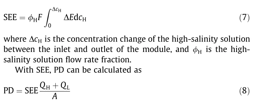
where QHand QLare the flow rates of the high-salinity and lowsalinity solutions, respectively; and A is the total membrane area.
As shown in Figs.4(a)and(b),for module-scale NPG operation,power density,PD,decreases with module size(membrane area,A)in both operation configurations.This observation can be explained by the concentration profiles of the solutions (Figs. 4(c) and (d)).With a larger A, more ions would be transported across the membrane, resulting in a decreased concentration difference between the high-salinity and low-salinity solutions along the module.Such a decreased concentration difference reduces the transmembrane potential difference along the module (Eq. (1)), and thereby leads to a decreased PD. Based on the above analysis, the PD in module-scale NPG operation would be further reduced from that in coupon-size NPG operation.
Grampy held my hand tightly. Together we looked up the street and down, and back up again. He stepped off the curb and told me it was safe to cross. He let go of my hand and I ran. I ran faster than I had ever run before. The street seemed wide. I wondered if I would make it to the other side. Reaching the other side, I turned to find Grampy. There he was, standing14 exactly where I had left him, smiling proudly. I waved.
In co-current flow configurations, SEE increases with A(Fig.4(a)),because a larger A allows more ions to transport through the membrane, resulting in more mixing of the two solutions(Fig. 4(c)), and thereby leads to a larger SEE. In counter-current flow configurations, SEE first increases and then decreases with increasing A(Fig.4(b)).Fig.4(c)shows that,as A increases,the outlet concentration of the high-salinity solution becomes lower, and the outlet concentration of the low-salinity solution becomes higher. With A increased from 10 to 25 m2, the outlet concentrations of the two solutions become closer, suggesting more mixing of the solutions, and consequently results in a larger SEE. With a further increase of A (i.e., from 25 to 50 m2), the outlet concentration of the high-salinity solution becomes even lower than that of the low-salinity solution,resulting in‘‘separation”of the two solutions rather than mixing.From a thermodynamic perspective,such additional ‘‘separation” consumes energy, and consequently leads to a reduced SEE.To avoid the additional‘‘separation”that reduces SEE in module-scale NPG operation, co-current flow configuration will be used in the remainder of this study.
In general, for module-scale NPG operation,a tradeoff between PD and SEE with respect to A can be observed.As discussed above,the increase of A results in more mixing of the solutions. On the one hand, more mixing of the solutions results in more Gibbs free energy of mixing that leads to a larger SEE. On the other hand,more mixing of the solutions reduces the concentration difference between the solutions along the module, resulting in a reduced driving force for ion transport, and thereby leads to a smaller PD.Therefore, to simultaneously obtain a large SEE and a large PD in module-scale NPG operation, the module size needs to be optimized.
4.3. Impact of load resistance on module-scale NPG operation
Since blue energy is harvested by a load resistor, the performance of NPG operation is notably influenced by the load resistance, rE. Fig. 5(a) shows that for given membrane area and solution flow rates in module-scale NPG operation, both PD and SEE first increase and then decrease with increasing rE. In fact,based on Eq.(8),in such scenarios,PD is proportional to SEE.Thus,the dependence of PD on rEcan be elucidated by the dependence of SEE on rE.
To determine the impact of REon SEE, the specific energy in module-scale NPG operation is illustrated by plotting electromotive voltage, E, as a function of a fraction of permeated ions with a fixed rE(Fig. 5(b)). As shown in Fig. 5(b), the useful work(i.e., SEE) is calculated from Eq. (7) and is represented by the red area. Due to concentration polarization (CP) effects, the potential drops across the boundary layers (i.e., the difference of E between the red and green curves)result in resistive losses in the CP layers,denoted by the green area. In addition, as the solutions are not completely mixed (i.e., not all available ions are permeated through the membrane), there is unutilized energy from the operation, indicated by the blue area. The sum of the useful work,resistive loss in the CP layers,and unutilized energy is equal to the SEEmaxthat can be calculated from Eq. (6).
Because the maximum extractable energy for given solution concentrations and flow rate fractions is fixed (Fig. 5(b) and Eq.(6)),the dependence of SEE on rEcan be elucidated by the changes of the resistive loss in the CP layers and unutilized energy with rE(Fig.5(c)).According to Eq.(3),an increased rEreduces the current in the NPG operation. Since the current is carried by the ions, a reduced current indicates a decreased ion flux. On the one hand,a decreased ion flux mitigates the CP effect in NPG operation,reducing the resistance in the CP layers,rBL(Fig.2(a)),and thereby decreases the resistive energy loss.On the other hand,the reduced ion flux suggests fewer ions permeating the NPG membrane, and increased incomplete mixing of the solutions, consequently leading to increased unutilized energy. Given the interplay between the resistive loss in the CP layers and unutilized energy,an optimal rEexists for achieving the maximum SEE and PD in module-scale NPG operation.
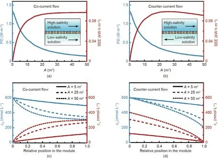
Fig.4. Performance of NPG with varied membrane areas in module-scale operation.Power density,PD(left vertical axis),and specific extractable energy,SEE(right vertical axis),as a function of membrane area,A,in(a)co-current flow and(b)counter-current flow NPG operation modes.The schematics of the co-current and counter-current flows are shown as insets in panels(a)and(b),respectively.Concentration profiles along the membrane module under(c)co-current flow and(d)counter-current flow operations with different A.In panels(c) and(d),the solid,dashed,and dotted curves denote concentration profiles of the high-salinity(cH,left vertical axis)and low-salinity(cL,right vertical axis) solutions with A of 5, 25, and 50 m2, respectively. The following conditions were used in the calculations: a negatively charged membrane, membrane ion conductance and selectivity of 108 S·m-2 and 1, respectively, initial concentrations of high-salinity and low-salinity solutions of 600 and 15 mmol·L-1, respectively; load resistance of 0.002 Ω·m2; flow rates of high-salinity and low-salinity solutions of 0.6 L·min-1;membrane channel width and height of 1 m and 1 mm, respectively, and the temperature of 298 K.

Fig.5. Performance of module-scale NPG with varied load resistances.(a)Power density,PD(left vertical axis),and specific extractable energy,SEE(right vertical axis),as a function of load resistance,rE.(b)Representative plot of useful work(red region),resistive loss in CP layers(green region),and unutilized energy(blue region)in a modulescale NPG operation with an rE of 0.002 Ω·m2. The vertical axis is the electromotive voltage, which is the driving force for ion permeation. The horizontal axis denotes the progress of ion permeation(the fraction of all ions available for permeation,Δnmax,taken by the permeated ions,Δn,which is indicative of the extent of mixing).(c)Specific energy breakdown in module-scale NPG operation as a function of rE. The green, red, and blue regions represent the resistive loss in CP layers, useful work, and unutilized energy,respectively.The following conditions were used in the calculations:co-current flow,a negatively charged membrane,membrane ion conductance and selectivity of 108 S·m-2 and 1,respectively;membrane area of 10 m2;initial concentrations of high-salinity and low-salinity solutions of 600 and 15 mmol·L-1,respectively;flow rates of high-salinity and low-salinity solutions of 0.6 L·min-1; membrane channel width and height of 1 m and 1 mm, respectively; and the temperature of 298 K.
4.4. Impact of solution flow rates on module-scale NPG operation
The performance of module-scale NPG operation is also dependent on the flow rates of the solutions. As shown in Fig. 6(a), PD increases with the flow rates of the high- and low-salinity solutions, because higher flow rates reduce the boundary layer thickness on each side of the membrane within the module, resulting in a larger PD. In comparison, SEE is a non-monotonic function of flow rate. The dependence of SEE on flow rate can be explained by the change of the specific energy with flow rate.For given solution concentrations and flow rate fractions, the maximum extractable energy is fixed (Eq. (6)). Higher flow rates reduce the boundary layer thicknesses, leading to a decreased resistive loss in the CP layers(Fig.6(b)).However,higher flow rates also shorten the residence time of solutions in the module, which reduces the extent of mixing of the solutions,and thereby increases the unutilized energy (Fig. 6(b)). Taking the resistive loss in the CP layers and unutilized energy into account, an optimization regarding the solution flow rates is needed to achieve the maximum SEE in module-scale NPG operation.
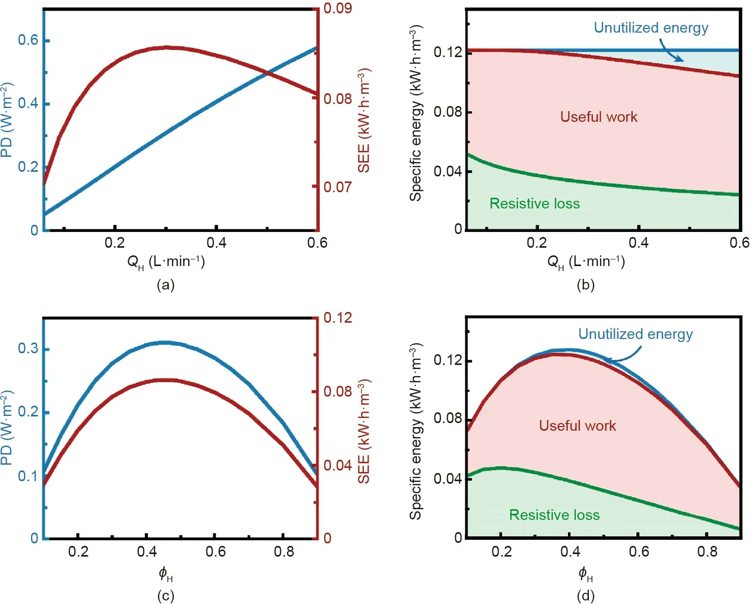
Fig.6. Performance of module-scale NPG with varied solution flow rates.(a)Power density,PD(left vertical axis),and specific extractable energy,SEE(right vertical axis),as a function of high-salinity solution flow rate,QH.The flow rate of low-salinity solution,QL,was assumed to be the same as QH.(b)Specific energy breakdown in module-scale NPG operation as a function of QH. (c) PD (left vertical axis) and SEE (right vertical axis) as a function of high-salinity solution flow rate fraction, φH. The sum of the highsalinity solution and low-salinity solution flow rates(i.e.,QH +QL)was set at 0.6 L·min-1.(d)Specific energy breakdown in module-scale NPG operation as a function of φH.In both panels (b) and (d), the green, red, and blue regions represent the resistive loss in CP layers, useful work, and unutilized energy, respectively. The following conditions were used in the calculations:co-current flow;a negatively charged membrane,membrane ion conductance and selectivity of 108 S·m-2 and 1,respectively;membrane area of 10 m2;initial concentrations of high-salinity and low-salinity solutions of 600 and 15 mmol·L-1;respectively,load resistance of 0.002 Ω·m2,membrane channel width and height of 1 m and 1 mm, respectively; and the temperature of 298 K.
In addition to the absolute flow rate values, the flow rate fractions of the solutions are also important in determining the performance of module-scale NPG operation. Fig. 6(c) shows that both SEE and PD first increase and then decrease with increasing φH.In fact, based on Eq. (8), for given total flow rates and membrane area, PD is proportional to SEE. Thus, both the dependences of SEE and PD on φHcan be explained by the change of specific energy with φH.According to Fig.6(d),the dependence of SEE on φHcan be mainly attributed to the change of maximum extractable energy with φH(Eq. (7)). The resistive loss in the CP layers would only slightly influence SEE because it first increases and then decreases with increasing φHas well. In addition, as the unutilized energy is almost unchanged with φH, its impact on SEE is negligible. Therefore, since the maximum extractable energy is maximized when φH≈0.4 (Fig. 6(d)), the maximum SEE and PD in module-scale NPG operation is achieved as φH≈0.45 (Fig. 6(c)).
5. Practical analysis of NPG systems operating with seawater and river water
5.1. Parasitic energy losses in NPG systems
Some inevitable energy consumptions exist in the operation of a practical NPG system.Unlike the synthetic working solutions used in bench-scale experiments, the water sources used in a practical NPG system require energy-demanding pretreatment processes to avoid performance deterioration and ultimate operation failure caused by membrane fouling and scaling [1,4,9,40,41]. Furthermore,additional energy is needed to supplement the pressure drop in the NPG system as the working solutions flow through the narrow spacer channels in the NPG membrane module [9,42].
Herein, we quantify the impact of the above discussed energy consumptions on the performance of a practical NPG system by analyzing the most commonly envisioned water sources for blue energy, namely seawater and river water. According to previous studies, the pretreatment energy consumptions of seawater and river water are assumed to be 0.1 and 0.05 kW·h·m-3,respectively[43-45]. Hence, the specific energy consumption (SEC) for pretreatment(i.e., total energy consumption of pretreatment normalized by the total volume of the working solutions), SECPT, can be estimated as (a detailed derivation is provided in Section S5 in Appendix A):
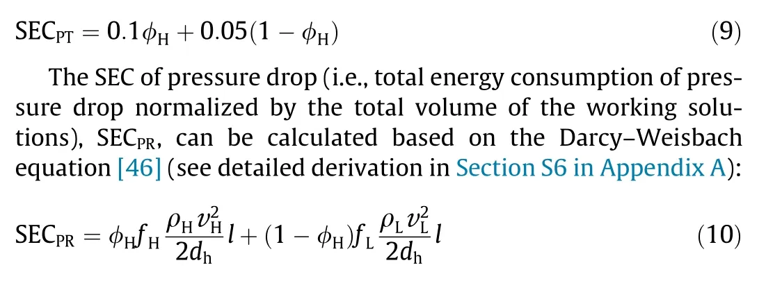
where ρHand ρLare the densities of the high- and low-salinity solutions, respectively;vHand vLare the average velocities of the high- and low-salinity solutions, respectively; dhis the hydraulic diameter of the channel spacers in the NPG membrane module; fHand fLare the friction factors of the high-and low-salinity solutions,respectively; and l is the length of the membrane channel.
5.2. NPG system net specific extractable energy and power density
Due to the parasitic energy consumptions, the net specific extractable energy, SEEnet, becomes a more relevant performance metric for assessing the viability of a practical NPG system compared with the SEE from the module-scale NPG operation,referred to as SEEgross[1,9]. SEEnetcan be calculated from SEEgross,SECPT, and SECPRas follows:

The specific energies in NPG systems with varied module sizes(i.e.,membrane area,A)are shown in Fig.7(a).Given the flow rate fraction of seawater (φH), SECPTremains constant with A, because the pretreatment cost of the working solutions is independent of the module size (Eq. (9)). Both SEEgrossand SECPRincrease with A.As explained in Fig. 3(a), the increase of SEEgrosscan be attributed to a more complete mixing of the working solutions with a larger A. Once A exceeds a certain value, SEEgrossreaches a plateau as the mixing of the working solutions is almost complete. By contrast,SECPRincreases linearly with A(Eq.(10)),because a larger A always results in more frictional loss.
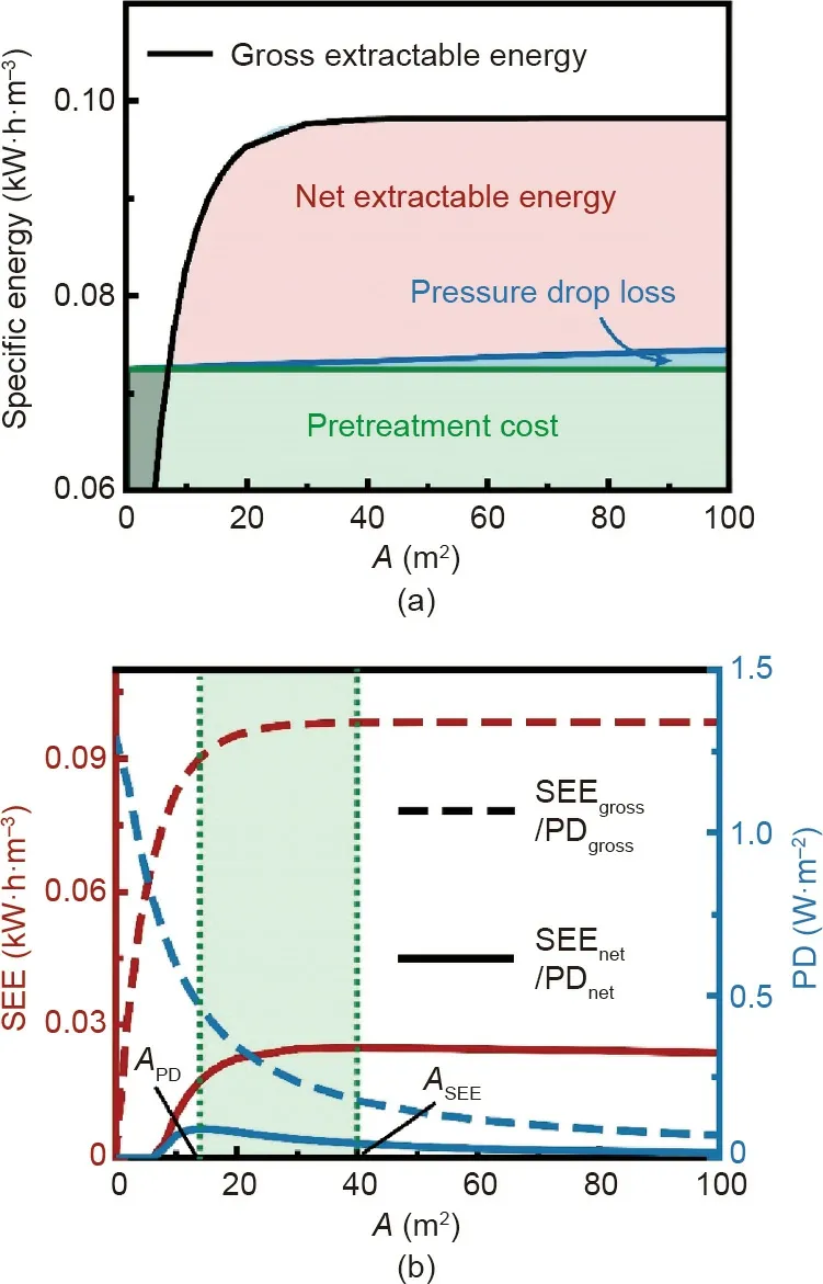
Fig.7. Performance of module-scale NPG operation with practical considerations of parasitic energy consumptions. (a) Illustration of net specific extractable energy calculation in NPG systems with different module sizes (or membrane areas). The black curve represents the specific gross extractable energy, SEEgross. Net specific extractable energy,SEEnet (red region),is obtained by subtracting the pretreatment cost of the solutions (green region) and pressure drop loss in the module (blue region) from SEEgross. The gray region refers to negative SEEnet. (b) Specific extractable energy, SEE (left vertical axis), and power density, PD (right vertical axis),as a function of module size(membrane area, A)in practical NPG operations.The solid curves represent SEEnet and PDnet,while the dashed curves denote SEEgross and PDgross.APD and ASEE denote the optimal A values for maximized PDnet and SEEnet,respectively, and the green region represents the optimal range of A for a practical NPG system. The following conditions were used in the calculations: co-current flow, a negatively charged membrane; membrane ion conductance and selectivity of 108 S·m-2 and 1,respectively;membrane area of 10 m2;seawater and river water concentrations of 600 and 15 mmol·L-1,respectively;load resistance of 0.002 Ω·m2;seawater and river water flow rates of 0.54 and 0.66 L·min-1,respectively;seawater and river water pretreatment costs of 0.1 and 0.05 kW·h·m-3, respectively;membrane channel width and height of 1 m and 1 mm, respectively; and the temperature of 298 K.
The calculated SEEnetof NPG systems with varied A is presented in Fig. 7(b). With a small A (i.e., A < 5 m2), no net energy can be extracted because SECPTfar exceeds SEEgross, suggesting that an NPG system with a small module is not feasible for energy production. Once A reaches a certain value, a positive SEEnetcan be obtained because SEEgrossis able to exceed SECPT,and the NPG system produces net energy, albeit, as we discuss later, at very low values that are not economically practical. As A further increases,SEEnetfirst increases and then decreases due to the interplay between SEEgrossand SECPR, indicating that there is an optimal module size, ASEE, for maximizing the SEEnetin an NPG system.With SEEnet, the net power density, PDnet, can also be obtained(Eq.(8)).The calculated PDnetof NPG systems with varied A is also shown in Fig.7(b).Like SEEnet,positive PDnetis achieved only if the module is large enough, and PDnetfirst increases and then decreases with increasing A. However, we note that the optimal module size, APD, for maximizing PDnetis different from ASEE, for maximizing SEEnet. Based on the previous discussion (Fig. 4(a)),such a difference can be attributed to the inherent tradeoff between PD and SEE with A.Therefore,for a practical NPG system,considering both SEEnetand PDnet, the optimal module size should fall between ASEEand APD.
As shown in Fig. 7(b), the SEEnetand PDnetare substantially lower than the SEEgrossand PDgross, respectively. Specifically, while the SEEgrosscan approach 0.1 kW·h·m-3, the maximum SEEnetis below 0.025 kW·h·m-3, suggesting that the parasitic energy consumptions can significantly compromise the energy production(~75%) in practical NPG systems. Likewise, although the PDgrossof a small membrane coupon can reach over 1 W·m-2,the maximum PDnetof a practical NPG system is lower than 0.1 W·m-2.Such a low PDnetreveals that, even if an NPG system is able to extract net energy, to achieve a target power output, the required membrane area (i.e., capital cost) with such an extremely small PDnethas to be huge. Therefore, considering the very low SEEnetand PDnet, the viability of NPG in harvesting blue energy from mixing seawater and river water is highly questionable.
6. Conclusions
In this study,we assessed NPG as a potential technology for harvesting salinity gradient(blue)energy in practical,real-world considerations. We found that due to the inherent phenomenon of concentration polarization, the power density in practical NPG operations with small membrane coupons can be several orders of magnitude smaller than the values deduced from bench-scale experiments in the literature (~106W·m-2). We also conducted module-scale analysis of NPG systems. In module-scale NPG analysis, both power density and specific extractable energy were calculated, and the impact of operating conditions on these two performance metrics has been thoroughly elucidated. Furthermore,using the net specific extractable energy and net power density as performance metrics, we show that the viability of a practical NPG system is significantly compromised by the parasitic energy consumptions of pretreatment and pressure drop during operation. Specifically, the obtained SEEnet(<0.025 kW·h·m-3)and PDnet(<0.1 W·m-2) are extremely low, and are insufficient for economical NPG power generation.
We note that our study focuses on investigating the impact of membrane properties and operating conditions in general NPG systems, while the influence of other system-design-related parameters (e.g., spacer channel thickness, electrode location, and electrode types) is neglected. Specifically, our analysis ignored the electrical resistances of bulk solutions in the spacer channels and the electrodes; these resistances further reduce NPG performance(i.e., extractable energy and power density). In addition, we assumed perfect ion selectivity of the NPG membrane and neglected the transmembrane water flux,thereby further exaggerating the estimated NPG performance. Notably, even with the apparently overestimated performance based on the results of our analysis, the NPG technology cannot be considered as a viable technology for harnessing blue energy from mixing seawater and river water.
Beyond our analysis, there are some additional challenges for the practical application of NPG technology,such as the fabrication of scalable NPG membranes and the unavoidable fouling issues of the NPG membrane. These challenges, although not discussed in our study, could further dampen the viability of NPG technology.
Importantly, NPG shares a similar working principle with RED.A prominent difference between NPG and RED lies in the nature of the membranes being used. Compared with the IEM used in RED,the ion conductance of NPG membranes is significantly larger.However,based on our analysis(Fig.2),NPG is not superior to RED in terms of power density because of the inherent concentration polarization. Another major difference between RED and NPG is the module configuration. In RED, cationic and anionic IEM pairs are employed, allowing complete mixings of both cations and anions for energy production. However, in reported NPG studies,a single negatively charged NPG membrane is used, allowing the mixing of only cations. This unique configuration of NPG results in the maximum extractable energy of NPG being only half of that of RED(Eqs.(5)and(6)),suggesting that NPG is not as competitive as RED for energy production. We emphasize that even if a positively charged NPG membrane could be developed in the future and utilized together with a negatively charged NPG membrane,the maximum extractable energy of NPG would only be equivalent to that of RED. Therefore, since NPG is not necessarily a more efficient technology than RED, its future for blue energy harvesting is highly questionable.
Acknowledgment
We acknowledge the financial support from the Center for Enhanced Nanofluidic Transport (CENT), an Energy Frontier Research Center funded by the US Department of Energy, Office of Science, Basic Energy Sciences through Award No. DESC0019112.
Compliance with ethics guidelines
Zhangxin Wang, Li Wang, and Menachem Elimelech declare that they have no conflict of interest or financial conflicts to disclose.
Appendix A. Supplementary data
Supplementary data to this article can be found online at https://doi.org/10.1016/j.eng.2021.02.016.
- Engineering的其它文章
- Science and Technology for Combating Global Water Challenges
- Brain-Computer Interface Speaks Up
- Solar Geoengineering to Reduce Global Warming—The Outlook Remains Cloudy
- Pandemic Scrambles the Semiconductor Supply Chain
- A Multi-Stage Green Barrier Strategy for the Control of Global SARS-CoV-2 Transmission via Cold Chain Goods
- Next-Generation Imaging: New Insights from Multicolor Microscopy in Liver Biology and Disease

