Recent Progress in Research and Development of Reconfigurable Intelligent Surface
YUAN Yifei,GU Qi,WANG Anna,WU Dan,LI Ya
(China Mobile Research Institute,Beijing 100053,China)
Abstract:We aim to provide a comprehensive overview of the progress in research and development of the reconfigurable intelligent surface(RIS) over the last 2–3 years in this paper,especially when the RIS is used as relays in next-generation mobile networks.Major areas of re‑search in academia are outlined,including fundamental performance,channel estimation,joint optimization with antenna precoding at base stations,propagation channel modeling and meta-material devices of RIS elements.Development in industry is surveyed from the aspects of performance potentials and issues,realistic joint optimization algorithms,control mechanisms,field trials and related activities in standardiza‑tion development organizations (SDOs).Our views on how to carry out the engineering-aspect study on RIS for 6G systems are also presented,which cover the realistic performance,the comparison with other topological improvements,approaches for channel modeling,factors for de‑signing control mechanisms and the timeline for RIS standardization.
Keywords:6G;reconfigurable intelligent surface;relay;meta-material;metasurface
1 Introduction
Since 3G mobile communications,the spectrum limita‑tion in licensed bands has pushed an expansion to the spatial domain to boost spectral efficiency.The multiple-input multiple-output (MIMO) technology in 4G and massive MIMO technology in 5G significantly im‑proved the system throughput and played a major role in fulfill‑ing the key performance requirements of IMT-Advanced and IMT-2020[1],respectively.To further exploit the spatial dimen‑sion of propagation channels,the reconfigurable intelligent sur‑face (RIS) has recently gained enormous attention both from academia and industry[2],as a strong candidate technology for 6G mobile networks.Propelled by the advancement in manu‑facturing of meta-materials and devices,RIS is able to improve the radio propagation environment and reduce the interference by tuning the amplitude and phase of RIS elements.Compared to repeaters and relays,RIS can operate in a passive manner without the need for power amplifier,thus allowing more flex‑ible deployment and opening a new paradigm for exploiting the spatial dimension for wireless communications.
There have been various activities across academia and in‑dustry on RIS.In academia,RIS workshops and panels are or‑ganized by the International Conference on Communications(ICC),Global Communications Conference (GLOBECOM),etc.every year.In August 2020,an emerging technology initia‑tive (ETI) on RIS was formed in IEEE[3].In the industry,com‑panies have submitted the proposals of studying RIS in the re‑lease time frame at 3GPP spanning January 2022 -June 2023.In June 2021,an industry specification group (ISG) for RIS was formed in ETSI to carry out the engineering related study and standardization of RIS.In China,task force groups on RIS were created in IMT-2030 (6G) Promotion Group and China Communications Standards Association (CCSA).Inter‑ested companies include mobile operators such as CMCC,NTT DOCOMO,China Unicom,China Telecom and KDDI,and vendors like ZTE,Huawei,vivo,CATT,etc.Some of them have already carried out preliminary field trials which demon‑strated great potential of RIS in realistic environment.There have been many symposiums,seminars and webinars on RIS,participated by both academia researchers and practical engi‑neers.RIS is an interdisciplinary effort which requires not only the expertise in mobile communications but also the deep knowledge in meta-surface material.Depending on the rate of amplitude and phase adjustment of RIS elements,RIS can be used either as relays deployed in the path connecting base sta‑tions and mobile terminals,or as part of antennas/radio fre‑quency components within base stations.Our focus in this pa‑per is the relay scenario of RIS application.
To facilitate the discussion,we use Fig.1 to represent a ba‑sic RIS-based downlink passive relay system where the base station (BS) is equipped withMtransmit antennas.The user equipment(UE)hasNreceive antennas.The channel connect‑ing the BS and the UE is denoted asHd.The other route goes through a RIS panel that hasKreflecting elements.The chan‑nel connecting the BS and RIS is denoted asH1.The channel connecting the RIS and UE is denoted asH2.The received sig‑nal at the UE can be represented as:

whereΦis a diagonal matrix in which each diagonal element represents the amplitude and phase response of a RIS element.The matrixVis the precoder applied at the BS transmit anten‑nas.The vectorscontains the modulated symbols to be trans‑mitted.The vectorn1is the noise vector received byNanten‑nas at the UE.Note that this model is quite general in the sense that the structure of RIS,as well as the antenna configurations of BS and UE,is not explicitly modeled.More intricate models would be needed for more practical performance studies.
The paper is organized as follows.In Section 2,progress in RIS research in academia is reviewed,including several major areas of research.Recent development of RIS in industry is discussed in Section 3 from multiple aspects.Section 4 con‑tains our views on some of the key components that would be important to future standardization and deployment of RIS.Section 5 concludes this paper.
2 Recent Research on RIS in Academia
2.1 Fundamental Performance of RIS
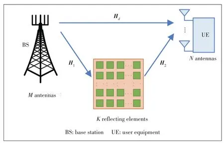
▲Figure 1.A basic reconfigurable intelligent surface (RIS)-based relay setup with multiple transmit antennas at BS and multiple receive anten⁃nas at UE
As RIS represents a paradigm change of traditional MIMO technology,it is worthwhile to study its fundamental perfor‑mance to develop some understanding of its potential,even though the initial assumptions are quite idealistic.In Ref]4],the authors studied the number of RIS elements (i.e.,Kin Fig.1) needed to show the benefit of RIS.The study assumed a setup with a BS and multiple users located in a square-shaped area as illustrated in Fig.2(a).There are obstacles between the BS and users.A RIS panel is placed between the BS and users to reflect the signal from the BS to the users,and vice versa.Closed-form formulae were derived for the system capacity of this setup,as well as the asymptotic capacity whenKgoes to infinity.It is seen from Fig.2(b)that the spectral efficiency in‑creases with the number of RIS elements,when the number of single-antenna users is five,the number of antennas at the BS is 10 (i.e.,M=10 in Fig.1),the carrier frequency is 5.9 GHz and the path loss exponential is around 2.5.The trend shows sign of saturation whenKgoes beyond 107,translated to the side of the RIS square of 56.7 m.With such an aperture size,the RIS is operating well within the near-field range.The study is very idealistic in the sense that the scenario is for single-cell without considering inter-cell interference or inter-RIS interference,that optimal phase adjustment is assumed without considering the phase granularity and control signal‑ing overhead,that channel estimation is perfect,and that the channel state information (CSI) is precisely known.Neverthe‑less,the result does reveal the importance of having enough number of RIS elements in order to deliver enough good per‑formance.
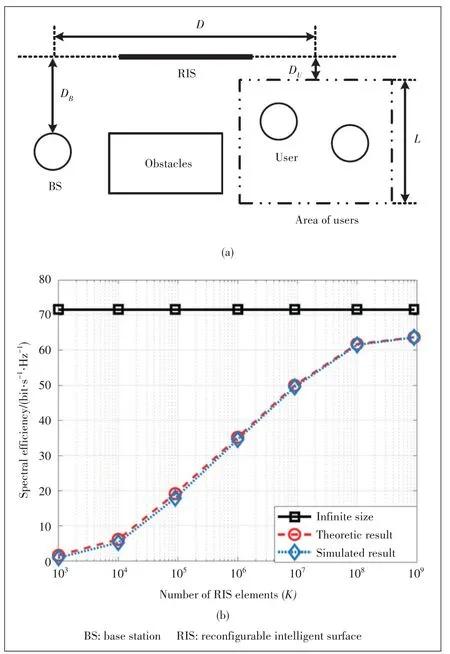
▲Figure 2.Setup in Ref]4]:(a) simulation layout for the RIS-based multi-user cellular network and (b) spectral efficiency vs.the number of RIS elements
While increasing the number of RIS elements (i.e.,Kin Fig.1) is beneficial to the system capacity,the cost of manu‑facturing and deployment of RIS panels are increased as well.Besides,the power consumption would generally grow with larger panels of RIS even if RIS is a quasi-passive device.In Ref]5],the optimum value ofKis derived to balance the spectral efficiency and energy efficiency,for a single cell sys‑tem equipped with single antenna at both the BS and the mo‑bile terminal.Control overhead is also considered,which ac‑counts for about 20% of total time/frequency resources.Under the normal setting of the parameters such as 30-45 dBm transmitting power of the BS and 110 dB of the path loss,it is found that the spectral efficiency of 20-25 bit‧s-1‧Hz-1can be achieved whenKis around 130-170.
2.2 Channel Estimations
Compared to traditional BS and mobile connections,RIS when serving as relays introduces more hops along the track from the BS to a mobile terminal.Even for the single reflec‑tion scenario as shown in Fig.1,two links need to be consid‑ered,ending up with a cascaded channel that is more compli‑cated and harder to estimate accurately.Channel estimation becomes very challenging for RIS containing hundreds or thousands of elements,yet the overhead of signals to estimate RIS channels has to be kept small.Considering that a BS is usually equipped with multiple antennas and the link connect‑ing BS and RIS (i.e.,H1) is changing slowly,a two-time scale channel estimation was proposed in Ref]6] where the estima‑tion ofH1is concentrated in the time slot with heavy density of pilot of both downlink and uplink,while the estimation of the link connecting RIS and the mobile (i.e.,H2)is carried out via the pilots residing in time scattered slots (Fig.3).The pilot concentration ensures the accurate channel estimation ofH1that is usually high-dimensional because of largeMandK.The relatively long period of concentrated pilot region can re‑duce the overhead without significantly affecting the estima‑tion accuracy due to the slow fading inH1.More frequent scat‑tered pilots can better track the time evolution of RIS-mobile channel (i.e.,H2).The light density of pilots in scattered slots helps to reduce the overhead without degrading the channel estimation,since the number of receive antennas at the mobile(i.e.,Nin Fig.1)is usually small.
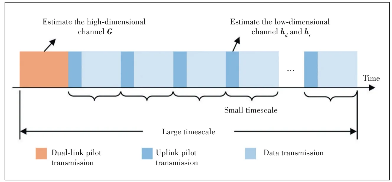
▲Figure 3.A two-time scale channel estimation for reconfigurable intelligent surface(RIS)aided system
Assuming that mobiles are equipped with a single antenna,a three-phase channel estimation framework was proposed in Ref]7].In Phase 1,the direct link connecting BS and the mo‑bile (i.e.,Hdin Fig.1) is estimated while the RIS is switched off.In Phase 2,only RIS and the typical mobile are turned on,so that the cascaded channelH2ΦH1can be estimated.In Phase 3,all other users are turned on to transmit the pilots.Assuming that the other users’reflected signals are scaledversion of the reflected signal of typical users,the cascaded channels of other users can be estimated efficiently.
While the BS-RIS channel (i.e.,H1) is often considered high-dimensional,the location of RIS is expected to be opti‑mized in practical deployment so that line-of-sight (LoS)propagation would be dominant.In this case,the cascaded channel would exhibit certain spatial sparcity especially in the millimeter band[8].Compressive sensing-based algorithms can be used to improve the efficiency of channel estimation.More advanced channel estimation methods would involve the iterative process to estimateH1andH2,respectively.In gen‑eral,RIS channel estimation algorithms,setting and configura‑tions highly depend on channel models and operation modes.
2.3 Joint Optimization with BS Precoding
As Fig.1 shows,both the BS and RIS would have multiple antennas or tunable elements,leading to very complicated joint optimization of BS precoding and phase control of RIS el‑ements.In Ref]9],an alternating weighted minimum mean squared error (WMMSE) algorithm was employed for MIMO of a RIS-aided single user.Here,the single user is in the sense that the BS precoder (i.e.,V) and element phase of RIS (i.e.,Φ) are optimized to maxi‑mize the link capacity of BS to a specific mo‑bile (including both the direct link and RISrelayed link),without considering other users.The optimization for the capacity formula is non-convex.Instead of being solved directly,the problem is solved alternately and itera‑tively as shown in Fig.4 where each subproblem is convex.Here,matrixUis the re‑ceive beamforming matrix,Eis the mean squared error (MSE) matrix,andWis the weighting matrix.As the iteration goes on,it would converge to the optimizedVandΦ.It is seen that even convergence can be achieved by converting the non-convex problem to a convex problem,multiple iterations are required,each involving a bunch of matrix multiplica‑tions.The overall computation complexity is high.It is ex‑pected that for RIS-aided multi-user MIMO,the optimization would be even more complicated.
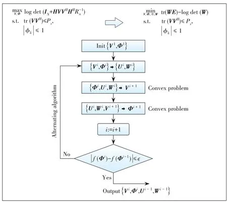
▲Figure 4.An alternating weighted minimum mean squared error(WMMSE) algorithm for joint optimization of reconfigurable intelli⁃gent surface(RIS)elements with base station(BS)precoding
The difficulty and complexity shown above are partially due to the unconstrained phase shifts of RIS elements (i.e.,Φ) and BS precoder (i.e.,V).Yet the practical RIS elements have limited resolution in phase adjustment.To reflect such limitation,the phase response of each RIS element is mod‑eled as ON and OFF in Ref]10].The number of receive an‑tennas at each mobile is assumed one (i.e.,N=1 in Fig.1)to encourage more multi-user MIMO transmission.With these assumptions and setting,the complicity of the joint optimiza‑tion can be significantly reduced,although an alternating type of algorithm is still used.The joint optimization problem can also be simplified by considering specific scenarios.For instance,millimeter wave (mmW) was the focus for RIS in Ref]11].Due to the less scattering in mmW propagation,the ranks of BS-RIS channel (i.e.,H1in Fig.1) and RIS-mobile channel (i.e.,H2) tend to be small.Hence,RIS element phase shifts (i.e.,Φ) can be optimized separately from the BS pre‑coder (i.e.,V).
In Ref]12],the joint optimization problem also counts in the non-ideal channel estimation.More realistic BS precoders,such as Hadamard-matrix based and discrete Fourier trans‑form(DFT)based codebooks,are considered.With these prac‑tical constraints,the optimization can be simplified to some extent without significantly degrading the performance.In Ref]13],the joint optimizing problem between RIS and BS was extended to multi-cell environment where many assump‑tions had to be simplified to make the problem tractable.
2.4 Channel Modeling
As an emerging technology,RIS is bringing significantly new operations of wireless networks with many unknowns,one of which is the channel characteristics of the cascaded chan‑nel.To certain extent,the difficulty of modeling the RIS chan‑nel lies in the relatively large size of RIS panels (which is typi‑cally required to achieve enough good performance as indi‑cated in Section 2.1),the large number of RIS elements (i.e.,Kin Fig.1),and the deterministic phase shifts of RIS ele‑ments (i.e.,Φ).Hence,a RIS panel cannot be treated as a cluster of scatterers as in traditional statistic channel models.The plane wave assumption which generally holds for tradi‑tional models may no longer be valid when the aperture of RIS panel is larger enough to meet the near-field criterion.There are some initial works[14-15]on RIS channel modeling based on Friis formula for line-of-sight propagation.For each RIS el‑ement (indexed by then-th row andm-th column),the receive radiation pattern and transmit radiation pattern are included in the calculation as seen in the second and third terms.

whered1is the distance between the transmitter and center of the RIS panel;d2is the distance between the receiver and cen‑ter of the RIS panel;dn,mis the distance between then-th rowm-th column element and the center of the RIS panel;rtn,mis the distance between then-th rowm-th column element and the transmitter;rrn,mis the distance between then-th rowm-th column element and the receiver.For simplicity,only eleva‑tion angleθis considered in this equation.The entire gain for the cascaded channel can be represented as:

wheredxanddyare the width and length of each RIS element,respectively;NandMare the total number of rows and col‑umns of the RIS panel,respectively.While the above study is only applicable to simple environments,those formulae help build an important foundation for more sophisticated propaga‑tion scenarios.In Ref]16],path-loss models were proposed for indoor and outdoor RIS,based on the real measurements for both 2.4 GHz and 28 GHz bands.It is seen that under the reasonable settings,the path loss of a cascaded channel sits between ITU-UMi (International Telecommunication Union-Urban Micro) LoS model and UMi NLoS (non-line-of-sight)model.As the number of RIS elements (i.e.,Kin Fig.1) in‑creases,the path loss becomes closer to that of the UMi LoS model.A 3D geometry-based non-stationary MIMO model was proposed for RIS-assisted system in Ref]17].An intricate cas‑caded model for RIS was proposed in Ref]18]where the node pruning technique was used in the graph representation of the cascaded model.
2.5 Meta-Material Devices
The characteristics of meta-material for RIS elements are crucial to the entire RIS system performance.Meta-material refers to a big family of man-made materials whose properties can be manipulated by introducing intricate wavelength-level or sub-wavelength-level structures at the surface.Note that the fundamental physical or chemical properties of the substances in meta-materials are not changed.For RIS elements,the most widely used devices are PN-diode or varactor based.With the fast development of computer simulation tools for electromag‑netic field circuits,the maturity of RIS device manufacturing has been elevated dramatically over the last few years,espe‑cially in terms of cost and durability,which makes it possible to build less expensive large RIS panels with hundreds or thousands of elements (i.e.,K>1 000 in Fig.1).While the fine tuning of element phases is still difficult,granularities of 2 bits or 4 bits are well within the reach of practical engineer‑ing nowadays.For instance,a three-level phase tunable RIS device was designed in Ref]19] for multi-beam antenna con‑figuration at round 5 GHz band operation.In Ref]15],two RIS panels were manufactured and employed for RIS channel model measurements at mmW bands.The first panel is rectan‑gular of size 7.8×56 mm2,containing 20×56=1 120 elements operating at 27 GHz.The second RIS panel is a square of side length 152 mm that has 40×40=1 600 elements operating at 33 GHz.In the field trials carried in Ref]19],the core part is a RIS panel designed by the authors.The rectangular panel operates at 5.8 GHz,built with varactor-based RIS devices.There are 20×55=1 100 elements and the phase of each ele‑ment can be tuned to~7 levels by applying different voltages as illustrated in Fig.5.No big fluctuation in the amplitude re‑sponse is observed across the frequency range of interest and the applied voltages.
3 Development in Industry
3.1 Performance Potential and Issues
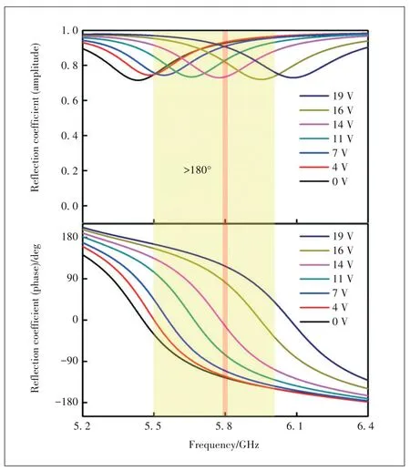
▲Figure 5.Amplitude and phase response of reconfigurable intelligent surface(RIS)elements vs.frequency and applied voltages[19]
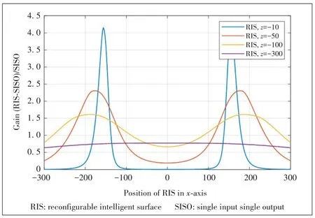
▲Figure 6.RIS performance gains over direct link as a function of distance
Performance evaluations have been carried out by a number of companies.With the basic setup as shown in Fig.1,we inves‑tigated the link level performance gain of RIS compared to that of the direct link,as illustrated in Fig.6.Single antenna BS and single antenna mobile are assumed here,e.g.,M=N=1.The RIS is square-shaped,containing 400 phase-tunable elements(e.g.,K=400=20×20)of half-wavelength spacing.The carrier frequency is 3 GHz.The antenna gains of BS,RIS element and UE are 5 dB,5 dB and 0 dB,respectively.LoS propagation is assumed between BS and RIS,and between RIS and UE.For the direct link(e.g.,BS and UE),the path loss is set so that the SNR equals 6 dB.Both mechanical tilt and phase adjustment are applied where the mechanical tilt (referenced at the center of the RIS panel) is determined by the Snell’s Law of reflec‑tion,and the phase adjustment is calculated according to the distance of an element to the center of the RIS panel.It is seen that in order to maximize the performance,the RIS panel should be placed close to either the BS or the mobile.Such phenomenon was also observed by ZTE.It can be explained as follows.When a RIS panel is close to a BS or a mobile,either BS-RIS link (e.g.,H1in Fig.1) or RIS-mobile link (e.g.,H2in Fig.1) is in the range of near field,as long as the RIS panel has a reasonable aperture size.In this case,the effective propagation distance of the cascaded channel tends to be the sum of propagation distances ofH1andH2,rather than the multiplication of propagation distances ofH1andH2,if ele‑ment phases of RIS can be adjusted appropriately.
System level simulations have been carried out by a few companies and the very preliminary results show the perfor‑mance benefits of RIS-aided relays under the multi-cell envi‑ronment.Nevertheless,the passive nature of RIS elements would cause inadvertent disturbance to the networks of other operators if the allocated bands of different operators are adja‑cent to each other,because RIS usually does not have filters.Thus,it is challenging to confine the impact of phase tuning within an allocated spectrum.
3.2 Practical Beamforming Algorithms for RIS
Considering the rather complicated joint optimization of BS precoder and phases of RIS elements which may require many iterations to reach convergence,it is desirable to come up with engineering feasible beamforming algorithms for RIS.There are several aspects that may be simplified in order to focus on key characteristics of RIS.For example,single-user transmis‑sion instead of multi-user may be prioritized,without taking into account the grating lobes.While both LoS and NLoS com‑ponents may be present in the channel,LoS may be empha‑sized,leading to low rank transmission and grid of beam (GoB)type of optimization.In another word,the signal to noise ratio(SNR)would be the main target for optimization,instead of the sum rate.In some situations,it may be wise to give up the full dynamic tuning of phases and opt for semi-static beamforming of RIS,as long as most of the performance of gains of RIS can be reaped.
3.3 Control Mechanisms of RIS
As mentioned previously,the RIS we considered in this pa‑per serves as a passive relay without the power amplifier.Nev‑ertheless,certain power consumption is still expected in order to adjust the phases of RIS element,to perform necessary digi‑tal processing and/or signal detection,etc.In such case,the RIS can be controlled in the following three ways.
The first one is through a wire connecting BS and the RIS controller.The advantage of wired connection is the simplified control protocol and lower power consumption.However,wires need to be reserved in this case,which would impose limita‑tions on deployment.The wired connection can be either Xn protocol based which was designed specifically for backhaul of mobile networks and normally has higher quality,or via In‑ternet Protocol (IP) routers that can be more easily plugged into the existing networks not necessarily built for radio ac‑cess networks.
The second alternative is via wireless link using a Uu air interface (connecting BS and UE) or non-Uu air interface.The major advantage of wireless connection between BS and the RIS controller is the more flexible deployment of RIS.Nevertheless,the Uu interface for RIS control requires stan‑dardization work which would take time to study and specify in standardization development organizations (SDOs),and may not be able to reach consensus in short time.Power con‑sumption is also assumed higher than the wired connection,given the higher propagation loss in the air and the less per‑centage of emitted electric-magnetic signal actually received by the mobile.There are also some issues with real-time con‑trol via wireless links.
The third approach is self-control/sensing of RIS which has the advantage of very flexible deployment and self-reliance.The self-control would be based on information sensing to pro‑actively measure the ambient environment,including the channels of BS-RIS and RIS-mobiles.Such a sensing based approach has the issues of high power consumption and perfor‑mance sensitivity to sensing capability and accuracy.The joint optimization with BS would be more challenging.
3.4 Initial Field Trials
Several companies have carried out initial trials of RIS.One of them is China Mobile,teaming up with Southeast Uni‑versity.Their trial took place at Nanjing,in the networks of China Mobile Jiangsu Province,which represents a dense ur‑ban environment.The operating band is 2.6 GHz.The environ‑ment includes both outdoor and indoor.The RIS panel has the size of 160×80 cm2and contains 32×16=512 elements (K=512 in Fig.1).Both the azimuth and vertical directions of RIS beams can be tuned,with 1-bit phase resolution.The RIS beam is manually tuned according to the BS beams and geolocations of the target UE,as well as the nearby propagation environment.Fig.7 shows the reference signal received power(RSRP),signal to interference noise ratio (SINR) and down‑link (DL) throughput measured along the driving path,with and without RIS.Cumulative density function (CDF) curves of RSRP,SINR and DL throughput are also compared between with and without RIS.It is observed from this trial that for us‑ers in good coverage,implementing RIS does not bring much benefit.However,for users in poor coverage,RIS can bring significant gains.
Since 2018,three trials of RIS have been conducted by NTT DOCOMO.The trial in 2018 showed magnitude-level throughput improvement when RIS was deployed along the city streets.In 2020,a prototype of transparent dynamic metasurface was demonstrated,which can be coated or in‑serted to window panels to improve the indoor coverage.In 2021,metasurface lens with the capability of focus control were presented.
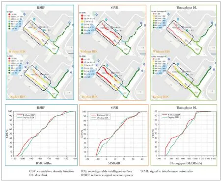
▲Figure 7.Initial trial results of RIS by China Mobile in Nanjing
Field trials of RIS by ZTE in Shanghai showed that RIS,if properly phase tuned,could drastically improve the received SNR.However,if the RIS was not powered,e.g.,no phase tun‑ing,the SNR would be similar to that without RIS.This means that the random phase reflection like in scatterers,would not constitute coherent phases,resulting in little benefit in the gain of SNR.
3.5 Related Discussions in 3GPP
Due to the strong interest in RIS from both academia and in‑dustry,a few companies like ZTE,China Unicom,KDDI,etc.have proposed a study item of RIS in 3GPP for Release 18 which is being carried out from January 2022 to June 2023.The scope of the proposed RIS study item includes use sce‑narios,channel models and performance evaluations of RIS.If possible,high level designs would also be discussed in the proposed study item.Still,the majority of companies in 3GPP felt that it was too early to kick off RIS which is generally con‑sidered as a 6G technology rather than a 5G+feature.There are many fundamental issues requiring more time for study in academia or in the industry.Many of them are not in the hand of experts in wireless baseband communications,for instance,the developments in device manufacturing and channel mod‑els of RIS,are also crucial.Once RIS is in the scope of 3GPP,the pace of its study would unavoidably be driven by tight schedules of delivering,which may not be beneficial to ex‑plore the full potential of RIS that would only be possible after a thorough analysis.
It is also noticed that in 3GPP Release 17 there was a work item in the RAN4 working group on the performance require‑ments for smart repeaters in 5G mobile networks.Hence,sev‑eral companies like China Mobile,Qualcomm,etc.proposed a study item of smart repeaters in the RAN1 working group (re‑sponsible for physical layer specifications) to investigate the control mechanisms for the repeaters.Different from the tradi‑tional repeaters that simply receive and amplify signals,smart repeaters can coordinate with the BS with regard to the time division duplex (TDD) subframes and beams for transmis‑sions.In RAN1,system level simulations for smart repeaters are expected,together with the discussion on side control in‑formation between BS and RIS for the subframe and beamforming coordination.Compared with RIS,the repeater is a more mature technology in the wireless.Smart repeater is just a small step further,with relatively small impact on the stan‑dards.Hence,it is likely that 3GPP Release 18 may include smart repeaters.
4 Views on RIS Study and Development
4.1 Performance Evaluation
It is expected that RIS panels would be deployed ubiqui‑tously in future networks where multiple RIS panels would be employed in a cell to improve both the coverage and data throughput.The performance should be evaluated in a multicell(Fig.8)and multi-user simulation setting,so that the inter-RIS and other cell interferences can be accurately captured.Considering that each RIS may contain hundreds of phasetunable elements,the entire multi-cell and multi-RIS system level simulation can be extremely complex,even when a rela‑tively simple channel model is assumed.Certain simplifica‑tions are needed to accelerate the computations in system simulations.
The simulations should reflect the coordination between the spatial precoding at BS in downlink (or at the mobile in up‑link) and phase tuning at the RIS panel.At the link level,the joint optimization algorithm to be simulated should be engi‑neering feasible,and can be modeled rather precisely in the physical layer abstraction (also called link-to-system map‑ping).The optimization algorithms should consider different levels of control over the RIS panel,such as granularity of phases or amplitudes of RIS elements and the time duration for the control(dynamic or semi-static).
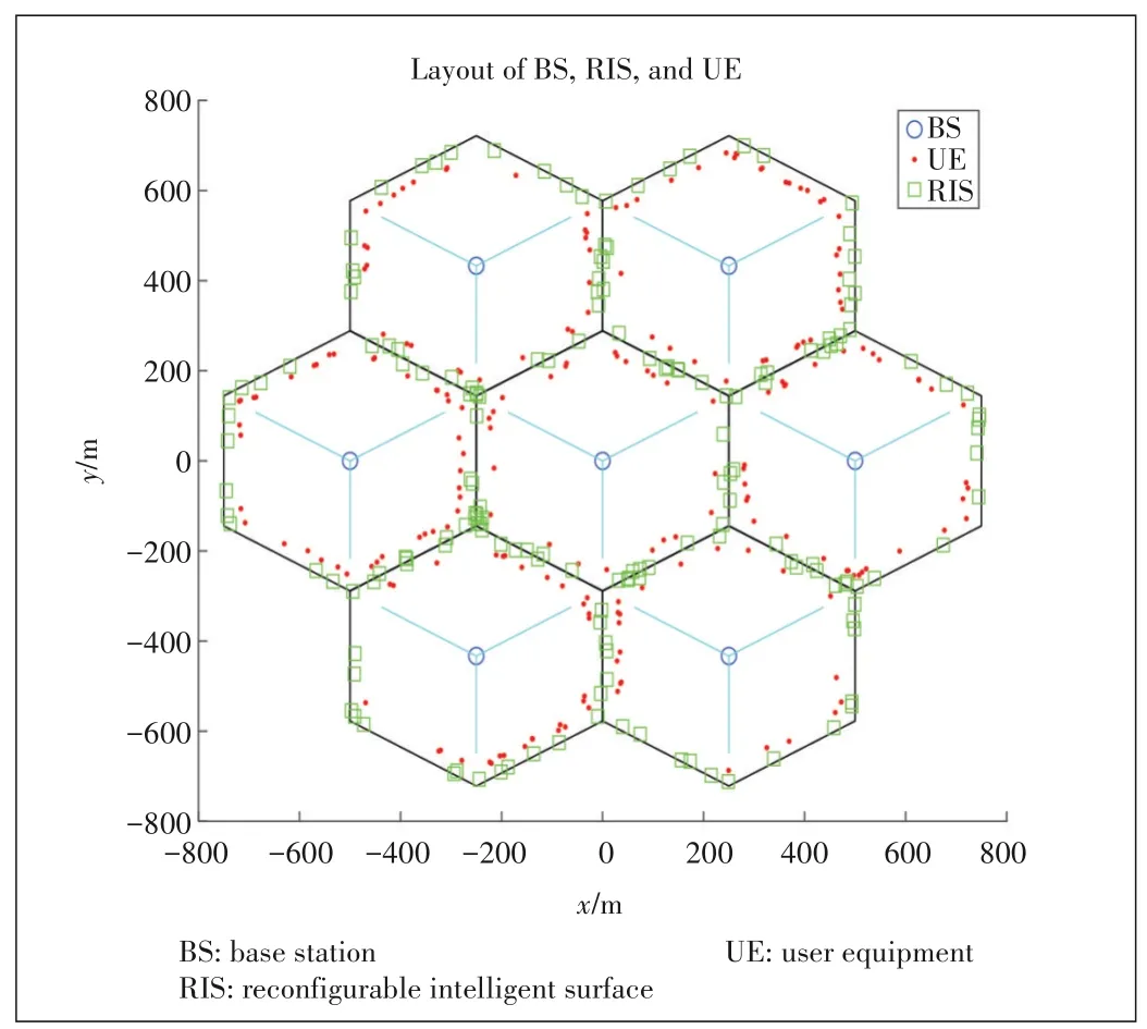
▲Figure 8.A multi-cell and multi-RIS layout for RIS system level simulation
The performance evaluation is not only for downlink and uplink traffic channels,which is crucial to quantify the po‑tential throughput gains of RIS.The performance of control channels,reflecting the basic coverage,should also be thor‑oughly simulated which include physical broadcast channel,primary and secondary synchronization channel,physical downlink control channel,preamble and messages for ran‑dom access,etc.
Overall,a new set of simulation methodology is needed for RIS,especially at the system level,to comprehensively balance the simulation complexity and the unique charac‑teristics of RIS systems.It should reflect typical deploy‑ment scenarios envisioned by operators,as well as suitable channel models.
4.2 Comparisons with Other Topological Improvements
In addition to the widely deployed homogeneous macro cell layout where the site-to-site distance,the antenna gains,the transmit power rating,etc.are more or less the same between different cells,heterogeneous networks (Het-Net) are often necessary to effectively serve sporadic hotspot areas or fill the coverage holes,by adding stationary lower power nodes on top of the macro layer.Such Het-Net is sometimes called topological improvement which can take the forms of micro BS,pico-BS or femto-BS,repeater,relays,etc.All of them are active nodes,meaning that they have power amplifiers.
Since 2010,3GPP has conducted extensive studies on these low power nodes,with abundant performance evaluation re‑sults which showed the significant gains in system throughput.The studies also revealed the inter-cell interference issues that require practical solutions either in pure implementation or with some impact on air interface standards.For instance,the introduction of micro/pico/femto cells causes severe inter‑ference from the macro cell to low power nodes and leads to significant coverage imbalance between the downlink and up‑link.The coverage imbalance issue can be mitigated by speci‑fying almost blank subframe (ABS).As one of the simplest low power nodes,a repeater can only amplify and then forward the signals from BS or mobiles,to mobiles or BS.Operations of re‑peaters are generally implementation specific and rarely re‑quire air interface changes.Relay,studied and specified in Release 10 Long-Term Evolution (LTE) of 3GPP,is essen‑tially a micro/pico/femto node with wireless backhaul.The backhaul link (e.g.,H1in Fig.1) and access link (e.g.,H2in Fig.1) operate in the same band in time-division multiplexed(TDM) manner.Different from repeaters,a relay is typically able to decode the received signal,re-encode and send the sig‑nal out,thus expected to have better performance.However,the standardization of the backhaul took a lot of effort,and the corresponding air interface specification was rather cumber‑some,hampering its wide use.So far,very few networks have deployed relays.
While RIS is a passive device that does not have power am‑plifier and can be more flexibly deployed,RIS shares many de‑ployment scenarios with relays and repeaters.For instance,all of them would likely be deployed by operators and their loca‑tions would be optimized to have higher probability of LoS propagation.Many experience and lessons from relay stan‑dardization can be helpful for RIS study and future standard‑ization:1) some simulation setup and evaluation methodology for relay may be reused for RIS;2) technical solutions for RIS systems should be efficient and practical,e.g.,to avoid compli‑cated or redundant schemes.
The study on smart repeaters can provide a very good refer‑ence for future RIS standardization.Firstly,the deployment scenarios of smart repeaters would be overlapped with those of RIS.Hence,the channel characteristics of backhaul link of smart repeaters and RIS would share many similarities in terms of antenna height,LoS probability,path loss,shadow fading,etc.;Secondly,certain control signaling is expected be‑tween BS and smart repeaters to facilitate the coordination.This signaling is likely to be sent over the air.Some control signaling is also anticipated between BS and RIS;Thirdly,both smart repeaters and RIS have very limited baseband pro‑cessing capability for baseband signals.
4.3 Practical Channel Models
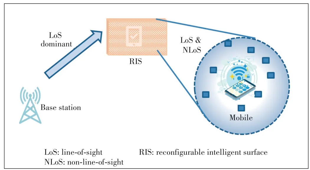
▲Figure 9.An example of statistical model for RIS cascaded channel
RIS channel modeling requires extensive measurements in different scenarios with various operating bands from sub-6 GHz to mmW.Channel models generally have two catego‑ries:statistical models and ray-tracing based models.In 3GPP,statistical models[20]are more widely used,while the ray-tracing based models are optional.The reason is that sta‑tistical models tend to generate the channel coefficients with more consistent and universal characteristics,rather than tar‑geting a specific layout of BS,scatterers and mobiles.The computation of statistical models is typically less burden‑some.These traits are crucial for the research study in SDOs such as 3GPP,to 1) have a generic and comprehensive model to reflect all typical layout and settings;2) facilitate the cross-checking of simulations and result comparisons be‑tween companies.In this sense,extension of statistical mod‑els to the RIS scenario may be a more practical approach,as illustrated in Fig.9 where the backhaul link channel is sim‑plified to be LoS dominant.It should be noted that many new parameters may need to be added,even if statistical models are to be used,considering the cascaded channel of BS-RISmobile.With hundreds or thousands of RIS elements in a panel,the computation complexity of the channel model can be daunting.More efficient characterization of RIS elements should be considered.
As discussed earlier,RIS performs well when it is placed close to BS or to mobiles.In this case,certain near field ef‑fect would be seen where the electromagnetic waves would not be strictly plane,e.g.,the wave front becomes spherical.This would certainly increase the complexity of channel mod‑eling and fading coefficient generation.Hence,some simplifi‑cation methods seem necessary to efficiently model the near field effect.
4.4 Physical Layer and Higher Layer Control Aspects of RIS
The discussion of RIS control highly depends on the mode of operation and the nature of future RIS products.For RIS panels with fixed amplitude and phase responses,the control is actually reflected during the pre-configuration when opera‑tors first lay out the panels.Such configuration heavily in‑volves proprietary solutions of network optimizations which are out of the scope of standardization.In such case,operators can directly purchase the static RIS panels from device manu‑facturers.For configurable RIS,it is a type of RIS-based relay node that has both a control unit and a RIS panel consisting of a large number of phase tunable elements.The potential manufacturers of this type of nodes may be traditional wireless equipment vendors or small vendors specialized in building low power nodes or passive devices,who may have different preferences about the functionalities of the RIS node.This would have big impact on the design of control mechanisms.One aspect is whether RIS panels are transparent or nontransparent to the mobiles being served.Transparent RIS re‑quires less control signaling and thus less standardization work,albeit with smaller room for performance optimization.Non-transparent RIS needs more procedures,more compli‑cated signaling and deeper involvement by mobiles,with the potential benefit of higher system throughput.
In order for RIS to work properly,four key technical aspects at the physical layer should have feasible solutions:1) chan‑nel estimation;2) CSI measurement and exchange;3) joint spatial precoding between BS and RIS;4) interference man‑agement.While many intricate schemes have been proposed for RIS in academic literature,a large percentage of them can hardly be de‑ployed in practical systems.They are sim‑ply too complicated and narrowly defined to be evaluated in SDOs such as 3GPP.Although the air interface standards would not specify the implementationoriented techniques such as joint precod‑ing and interference management,some basic or typical algorithms for implementa‑tion would be decided in SDOs to facilitate the simulations and cross-verification.The control of RIS also involves a higher layer,for instance,how to verify,register and configure a RIS node when first deployed in the network.
4.5 Standardization Timeline in 3GPP
As the most important SDO in the world for mobile com‑munications,3GPP will be the most influential industrial platform to specify the necessary technology of RIS and fos‑ter an eco-system for wide deployment of RIS in future mo‑bile networks across the globe.Nevertheless,as mentioned above,many companies in 3GPP,including China Mobile,have expressed views that it is immature to kick off the study on RIS in Release 18.On the other hand,we believe that it is beneficial to carry out the study on smart repeaters,as an intermediate stage for RIS,to get more understanding about the potential gain of topological enhancements and ac‑cumulate more knowledge prepared for RIS.As a revolution‑ary technology,RIS requires more time and experience for build-up.It should be emphasized the kickoff of RIS in 3GPP should not be too late either,considering that the en‑thusiasm on RIS by the academic community has already lasted for about 3 years.At a certain point,the industry com‑munity should be deeply involved,to provide clearer and consolidated feedback to academia,on which directions should have high priority.In our view,it is desirable to kick off a 3GPP study item of RIS in Release 19 starting from June 2023,as illustrated in Fig.10.The study item may last over the entire duration of Release 19 (expected to end in December 2024) to have ample time for study and evalua‑tion of RIS.
5 Conclusions
In this paper,we provide a picture of the research and de‑velopment of RIS for relay use,both in academia and industry.Significant progress is observed in potential performance,channel estimation,joint precoding between BS and RIS,con‑trol mechanism,channel modeling,RIS device manufacturing,etc.Views on future work on RIS are also presented,including the comparison and experience sharing with other topological enhancement technologies,and the preferred timeline to kick off the RIS study in 3GPP.
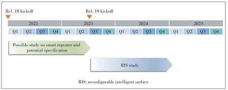
▲Figure 10.Time frame for possible kickoff of RIS study item in 3GPP
- ZTE Communications的其它文章
- Editorial:Special Topic on Reconfigurable Intelligent Surface (RIS)
- Some Observations and Thoughts about Reconfigurable Intelligent Surface Application for 5G Evolution and 6G
- New Member of ZTE Communications Editorial Board
- Recent Developments of Transmissive Reconfigurable Intelligent Surfaces:A Review
- IRS⁃Enabled Spectrum Sharing:Interference Modeling,Channel Estimation and Robust Passive Beamforming
- Resource Allocation for Two⁃Tier RIS⁃Assisted Heterogeneous NOMA Networks

