
Exploitation of Waste Heat from a Solid Oxide Fuel Cell via an Alkali Metal Thermoelectric Converter and Electrochemical Cycles
2021-12-21 05:51ZHAJingjingHUANGYuewu
ZHA JingjingHUANG Yuewu
College of Environmental Science and Engineering, Donghua University, Shanghai 201620, China
Abstract: In order to employ the waste heat effectively, a novel three-stage integrated system based upon a solid oxide fuel cell (SOFC), an alkali metal thermoelectric converter (AMTEC) and thermally regenerative electrochemical cycles (TRECs) is put forward. Considering the main electrochemically and thermodynamically irreversible losses, the power output and the efficiency of the subsystems and the integrated system are compared, and optimally operating regions for the current density, the power output, and the efficiency of the integrated system are explored. Calculations demonstrate that the maximum power density of the considered system is up to 7 466 W/m2, which allows 18% and 74% higher than that of the conventional SOFC-AMTEC device and the stand-alone fuel cell model, respectively. It is proved that the considered system is an efficient approach to boost energy efficiency. Moreover, the influence of several significant parameters on the comprehensive performance of the integrated system is expounded in detail, including the electrolyte thickness of the SOFC, the leakage resistance of the SOFC, and the area ratio between the SOFC electrode and the AMTEC subsystem.
Key words: solid oxide fuel cell(SOFC); thermally regenerative electrochemical cycle; alkali metal thermoelectric converter(AMTC); hybrid system; performance comparison
Introduction
The exhausted fossil energy and escalating environmental crisis have become the major stumbling blocks in the development process of low-carbon economy[1-2]. As one of the most promising renewable energies, the fuel cell can realize the direct conversion from chemical energy into electricity[3]. Among all fuel cells, solid oxide fuel cells (SOFCs) have been highlighted, because of their inherent advantages such as low emission, flexible fuel, and cheap metal catalyst[4-6]. Apart from power production, SOFCs also produce significant amounts of waste heat, which provide opportunities for bottoming thermodynamic devices. Ebrahimi and Moradpoor[7]designed and analyzed a micro-scale electricity generation cycle consisting of a SOFC, a micro-gas turbine, and an organic Rankine cycle. Fuel-saving and the overall efficiency of the cycle were up to 45% and 65%, respectively. Zhangetal.[8]employed a thermoelectric generator (TEG) and a thermoelectric cooler to utilize exhaust thermal energy from the SOFC for power generation and cooling provision. Research results showed that the power output density and the energy efficiency of the model obtained some improvements by 2.3% and 4.6% with respect to the stand-alone SOFC, respectively. Khanietal.[9]developed and analyzed a coupling system comprised of a gas turbine, a generator-absorber-heat exchange absorption refrigeration cycle and a SOFC, based on thermodynamics and economics. They observed that the exergy efficiency of the coupling device would be about 7% greater than that of the single fuel cell model.
As a promising static energy conversion system, alkali metal thermoelectric converters (AMTECs) can realize higher Carnot efficiency at lower working temperature. AMTECs have exhibited outstanding characteristics including noiseless, no moving parts, and reliability. Hence, it is significantly meaningful that the AMTEC is employed to convert the excluded thermal energy of high-temperature fuel cells. The mathematical model of direct carbon fuel cell (DCFC)-AMTEC cogeneration system was demonstrated by Pengetal.[10]. A reasonable matching project of two sub-devices was obtained. Since the AMTEC can achieve 400-700 K in the cold end, it is a valuable work to recover the heat from the condenser of AMTECs. Wuetal.[11]presented an updated concept of an AMTEC-TEG hybrid model. It was observed that the maximum conversion efficiency of the considered model was 3.91% greater than that of the conventional AMTEC model. Wangetal.[12]hybridized an absorption refrigerator to an AMTEC for cooling production and revealed that the peak power output of the developed device reached 22.94 W, while that of the stand-alone AMTEC was 14.83 W. The thermally regenerative electrochemical cycles (TRECs) have the potential to act as a bottoming cycle in an integrated system, because they can efficiently utilize low-grade thermal energy. For instance, Zhangetal.[13]used TRECs to harvest the excluded thermal energy from alkaline fuel cells, and observed that the peak power density was approximately 1.5-1.8 times of the calculation from the fuel cell model. Wangetal.[14]evaluated the performance of hybrid devices that coupled TREC to photovoltaic (PV) arrays. The results indicated that TRECs was efficiently driven by the PV array and achieved better performance.
With an aim to performance enhancement, a novel three-stage thermal power system consisting of SOFCs, AMTECs and TRECs is constructed. Taking various internal and external irreversible losses into account, the analytic formulas for evaluating the performances of SOFCs, AMTECs, TRECs and considered system are derived. The merits of the developed integrated system will be demonstrated by comparisons to the single SOFC and SOFC-AMTEC coupling system. With the help of the theoretical model, some significant parametric analysis on the SOFC-AMTEC-TREC integrated system is conducted.
1 System Description
As depicted in Fig. 1, the three-stage thermal power system comprises a SOFC, an AMTEC and TRECs. The SOFC operated at temperatureThturns the chemical energy into power energyPS, and useless thermal energy simultaneously. A portion of the rejected heat from the SOFCQ1, is transferred to drive the AMTEC for power productionPA, and the rest portionQL, will be released to the environment. The AMTEC subsystem mainly consists of an evaporator, a condenser, BASE, porous wicks, and sodium (Na) is employed as the working medium[15]. The role of the bottoming TRECs is to generate useful energyPTby utilizing waste heat. With an aim to simplify the heat transfer model, it can be presumed that the condenser temperatureTof AMTEC is the same as the high temperature end temperatureT1of TRECs , meanwhile, the low temperatureT2of TRECs is identical to the ambient temperatureTc.
For simplicity, several reasonable assumptions are adopted[5, 13, 16-17].
(1) The whole system operates under a steady state.
(2) Working temperature and pressure of the SOFC are considered constant.
(3) All heat transport in the model is abide by Newton's law.
(4) Reactants perform perfectly in the SOFC.
(5) The heat loss from the AMTEC to the surroundings is not considered.
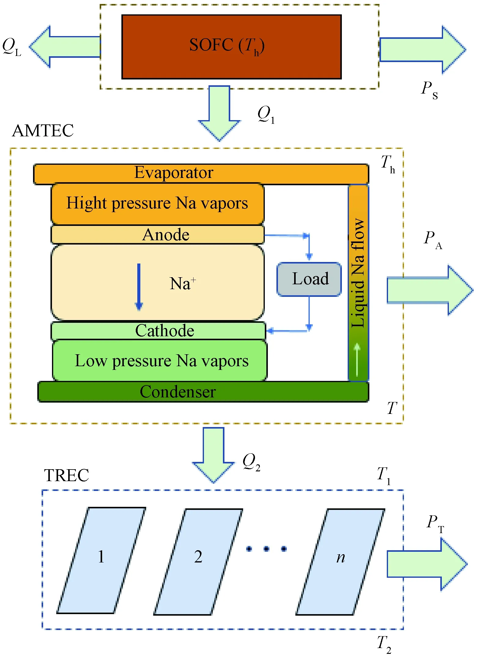
Fig. 1 Diagram of a SOFC-AMTEC-TREC integrated system
1.1 SOFC

VS=E-Vact, a-Vact, c-Vcon, a-Vcon, c-Vohm=
(1)
PS=-△G-T0Stot=-△G-JASVS-(E-VS)2/
(2)
(3)
where
(4)
(5)
(6)
Jrepresents the current density;Findicates Faraday's constant;nestands for the number of electrons;JL, a/cmeans the anode/cathode limiting current densities;J0, a/ccharacterizes the exchange current densities of the anode/cathode;Eeldenotes the activation energy for ion transport;ASindicates the effective polar plate area; △h0and △g0denote the Molar enthalpy change and Gibbs free energy change values atp0=101 325 Pa, respectively.Leldenotes the thickness of electrolyte of a SOFC;σ0stands for reference ionic conductivity;Rintis internal resistance;Rleakis leakage resistance;Rrepresents the universal constant;pH2,pO2, andpH2Omean the partial pressures of reactants H2,O2, and H2O, respectively.
1.2 AMTEC
As described in Fig. 1, the AMTEC operates between the SOFC and the TREC. The AMTEC is divided into two zones. One is the high temperature zone with evaporator (900-1300 K), and the other is the low temperature zone with condenser (400-800 K)[12, 19]. The net heat inputQin, power outputPAand efficiencyηAare calculated as
(7)
PA=IAVA,
(8)
and
(9)
wherezstands for the geometric factor of radiation losses;IAis the current;Mmeans the molecular mass of sodium;Lindicates the latent heat of vaporization of Na;cpis the molar specific heat;σis the Stefan-Boltzmann radiation constant;Aadenotes the electrode area;VAis the voltage output of the AMTEC, which is given by[20-23]
(10)
wheref=F/RTh,Psat(T)=109.678-5 383.2/T,Vacstands for the over potential difference, andVRmeans the ionic BASE voltage.
VacandVRcan be expressed as[20-22]

(11)
and
(12)
It is worth noting that the relationship betweenTandThis
(13)
The AMTEC subsystem is validated with the experimental data from Cole[24], as displayed in Table 1. In Fig. 2, we can see that the predicted outcomes are in good agreement with the testing data, which fully demonstrates the reliability and rationality of the AMTEC subsystem adopted in this paper.

Table 1 Comparison between simulation results and testing data from Cole for AMTEC subsystem

Fig. 2 Comparison between simulation results and testing data from Cole
1.3 TREC
In a TREC, the working principle is described by Fig. 3. In order to effectively recover the thermal energy generated in AMTEC and produce continuous useful power energy, a portion of TRECs serves as the hot unitT1in contact with the AMTEC condenser, a portion of TRECs serves as the cold unitT2contacting with the environment, and the rest of TRECs performs the regeneration process[13, 25-26]. The expression of the heat input and output can be obtained as[5, 17, 27]
(14)
(15)
where △T=T1-T2;ηRdenotes the regenerative efficiency;αstands for the temperature coefficient of TRECs;mrepresents the amount of the cells charged at the same time;Imeans the electric current;RLis the internal resistance;CpandCqmean the specific heat capacity and specific charge capacity of an electrochemical cell.
Based on Eqs. (13) and (14), the power outputPTand efficiencyηTof TRECs are derived as
PT=Qin-TREC-Qout-TREC=m(αI△T-2I2RL) ,
(16)
(17)

Fig. 3 T-S diagram of a TREC
1.4 Integrated system
According to the first law of thermodynamics, one section of the thermal energy generated by the SOFC is transferred to the AMTEC (Q1), the other section is expelled into the environment (QL), and the heat flux transferred from the AMTEC to TREC (Q2) can be deduced as follows:
Q1=-△H-PS-QL,
(18)
(19)
(20)
whereALstands for the corresponding heat leakage area;KLis the heat leakage coefficient;εlrefers to the effective thermal emittance of the SOFC. When -△H-PS-PA>QL,TRECs start to operate.
By using Eqs. (2)-(16), the power outputPand efficiencyηof the model are deduced as
P=PS+PA+PT=
(21)

(22)
2 Generic Performance Characteristics and Comparisons

(23)
ηP≤η≤ηm,
(24)
and
Jη, m≤J≤Jm.
(25)
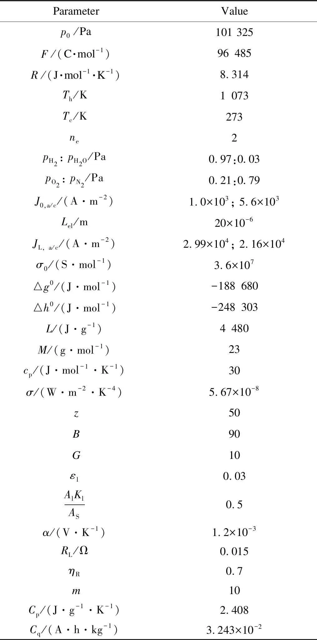
Table 2 Parameters utilized in proposed system

Fig. 4 Comparisons of (a) power output densities and (b) efficiencies between the SOFC, AMTEC, TRECs, SOFC-AMTEC and proposed system
3 Parametric Studies
3.1 Influence of electrolyte thickness on SOFC


Fig. 5 Three-dimensional graphs of (a) power densities and (b) efficiencies changing with J and Lel
3.2 Influence of leakage resistance on SOFC


Fig. 6 Three-dimensional graphs of (a) power densities and (b) efficiencies changing with J and Rleak
3.3 Influence of area ratio
Xrepresents the area ratio between the SOFC electrode and the AMTEC subsystem, that is,X=Aa/AS. Figure 7 demonstrates the influence of area ratioXonP*andη. It is founded thatP*andηare obviously improved asXincreases.
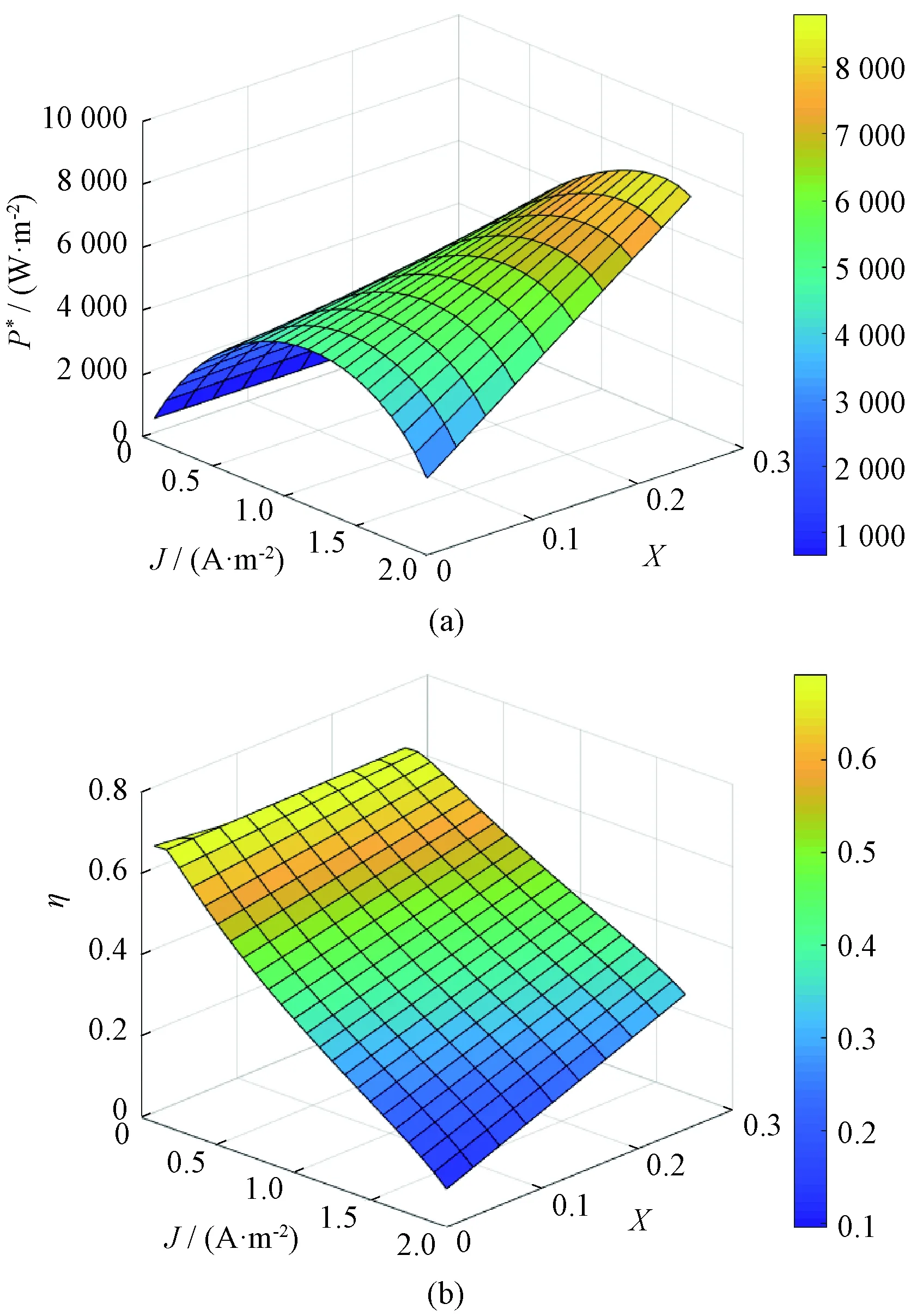
Fig. 7 Three-dimensional graphs of (a) power densities and (b) efficiencies changing with J and X

4 Conclusions
A novel three-stage integrated system employing an AMTEC and TRECs to recover thermal energy from SOFCs for electricity production is theoretically established. Mathematical formulas for the efficiency and the power output density of the SOFC, AMTEC, TRECs, and integrated system are deduced. Some critical parametric investigations are implemented to explore how the developed model performance is impacted by some parameters. The main obtained results are as follows.
(1)From comparisons with the SOFC-AMTEC and the single SOFC, it is proved that the proposed three-stage integrated system is an effective architecture to enhance energy utilization efficiency.
(2)The leakage resistance of the SOFC and the area ratio between the SOFC and the AMTEC have positive impacts on the enhancement of proposed system performance, while an improvement in electrolyte thickness of SOFC degrades the hybrid system performance.
It is worth noting that manufacturing costs and investment for the developed model can be raised because of the application of the AMTEC and TRECs. However, these costs would be recoverable through additional electric power generation over a long period of time.
 Journal of Donghua University(English Edition)2021年6期
- Journal of Donghua University(English Edition)的其它文章
- Effect of Surface Energy of Electrospun Fibrous Mat on Dynamic Filtration Performance for Oil Particles
- Seam Damage Control and Image Analysis for Cuprammonium Fabrics
- Robust Waterborne Polyurethane/Wool Keratin/Silk Sericin Freeze-Drying Composite Membrane for Heavy Metal Ions Adsorption
- Textile-Based Capacitive Pressure Distribution Measurement System for Human Sitting Posture Monitoring
- Enhancing Accuracy of Flexible Piezoresistive Pressure Sensors by Suppressing Seebeck Effect
- Reduced Switching-Frequency State of Charge Balancing Strategy for Battery Integrated Modular Multilevel Converter