Research on Direct Torque Control of Permanent Magnet Synchronous Motor for New Energy Vehicles
Zhenzhou Niu Xiaopeng Li
Tianjin University of Technology and Education, Tianjin, 300222, China
ABSTRACT This article introduces the control principle, technical status and two commonly used motor control schemes of permanent magnet synchronous motors for new energy vehicles.Direct torque control is selected as the research object, and its advantages and disadvantages with vector control are analyzed.A Simulink simulation model was established according to the control principle.
Keywords:Motor control strategy Control principle Direct torque control
1.Introduction
The core technology of new energy vehicles is the “Three electric”, including power batteries, drive motors and motor controllers.Power batteries are the energy source of the entire new energy vehicle.The drive motor is the power core of the vehicle.The motor controller can control the speed, torque and direction of the drive motor according to the received instructions.Currently, power batteries have limited capacity and are expensive.New energy vehicle drive motors can be divided into DC motors, AC asynchronous motors, permanent magnet synchronous motors and switched reluctance motors.Among them, AC asynchronous motors and permanent magnet synchronous motors are the most widely used in new energy vehicles.However, in China, permanent magnet synchronous motors occupy a dominant market position by virtue of their high power-density and small size, etc.According to data from the Ministry of Industry and Information Technology, as of June 2019, the domestic installed capacity of drive motors was 650,000, of which permanent magnet synchronous motors accounted for 99% of the market.Before a major breakthrough in battery technology, how to improve the power and endurance of new energy vehicles will be the primary problem faced by new energy vehicle designers.And high-efficiency motor control technology will be one of the ways to solve this series of problems.
2.Principles of Motor Control
The drive motor system of new energy vehicle is a combination of the drive motor, the drive motor controller and the auxiliary devices necessary for its work.The drive motor system is the main executive system in the driving of new energy vehicles, and its driving characteristics determine the main performance indicators of the car.The high-voltage power output by the power battery is distributed by the high-voltage control box, and then the high-voltage DC power is inverted into three-phase AC power by the drive motor controller.Finally, the drive motor converts electrical energy into mechanical energy[1].The high-voltage transmission line is shown in Figure 1.

Figure 1.Electric vehicle high-voltage transmission line diagram
The drive motor is mainly composed of stator, rotor, sensor and shell.The rotor of a permanent magnet synchronous motor is generally composed of an iron core and a permanent magnet.According to the installation position of the permanent magnet on the rotor, the rotor type can be divided into surface mount type and embedded type.When a three-phase alternating current is applied to the stator of the motor, a stable rotating magnetic field is generated inside the motor.The magnetic field of the rotor is subjected to the electromagnetic force of the stator magnetic field, so that the rotor rotates synchronously with the stator magnetic field to generate electromagnetic torque.
The motor controller is mainly composed of the main control unit, drive module, power module, housing and cooling system.The main control unit is the “brain” of the motor controller, with underlying software and control algorithms written inside, which can realize motor control based on accelerator pedal signals, motor resolver signals, CAN signals, etc.The function of the drive module is to output a pulse width modulation signal to control the power module after receiving the signal from the main control unit.The power module is generally an insulated gate bipolar transistor (IGBT), which can realize the inversion from direct current to alternating current by controlling the on and off of the IGBT, and can also rectify the alternating current recovered during braking into direct current.IGBT is a composite full-controlled voltage-driven power semiconductor device composed of a bipolar transistor and an insulated gate field effect transistor, which works in a saturated state and an off state.When the IGBT is working in a saturated state, the circuit is turned on, and when the IGBT is working in an off state, the circuit is turned off.The motor control structure is shown in Figure 2.

Figure 2.Motor control structure diagram
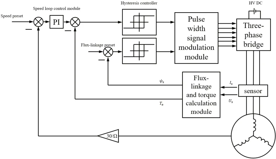
Figure 3.Principle of Direct Torque Control
3.Current Statue of Motor Control Technology
Since the 21st century, with environmental, climate and energy issues, governments of various countries have issued a series of policies to promote the development of electric vehicles.This has allowed the production and sales of electric vehicles to grow steadily, and it has also driven the rapid development of motor control technology.
Motor control technology is divided into hardware part and software part, and its development follows the development of microelectronics, computer, materials science and other disciplines[2].The hardware part is composed of microcontroller, drive module, insulated gate bipolar transistor (IGBT), sensor and protection circuit.The software part consists of motor control algorithm, motor status detection and safety monitoring, rotor position decoding algorithm and so on.
The core of the hardware part is mainly the microcontroller and IGBT.For the microcontroller, the working environment inside the car is relatively harsh, and its reliability and safety requirements are also higher.Therefore, the microcontroller must be certified by the reliability standard AEC-Q100, the quality management standard ISO/TS16949, and the functional safety standard ISO26262 before it can be used in the car.In 2019, NXP accounted for the largest proportion of the global automotive chip market, reaching 14%, and Infineon was second only to NXP, accounting for 11%.
Most of the manufacturers of electric vehicle power modules are concentrated in Western countries and Japan.Among them, Infineon, Mitsubishi Electric, Semikron, Fuji Electric and other companies have launched products specifically for automotive-grade IGBTs.My country’s BYD, STARPOWER and other companies have also entered the fast lane in the IGBT industry.Among them, STARPOWER ranked 8th in the global market share of IGBT modules in 2018, and it is also the only Chinese enterprise that has entered the top ten in the world.In terms of IGBT technical strength, BYD released IGBT 4.0 in 2018, which is equivalent to the fifth-generation technology in the world.STARPOWER has developed to the sixth-generation technology, and the highest international level is the current level of Mitsubishi Electric.It can be regarded as 7.5 generation technology.
The core of the software part is mainly the control algorithm of the motor.The commonly used control methods of permanent magnet synchronous motors are vector control and direct torque control.Both of these control methods can realize the high dynamic performance of the motor and variable frequency speed regulation.But because of the characteristics of these two control methods, they have their own different best application scenarios.
Vector control, proposed by Hasse of Darmstadt University of Technology in the late 1960s.The main idea of this control method is that the excitation current and armature current of the reference DC motor are perpendicular to each other, are not coupled, and can be controlled independently.Vector control decouples the stator current in the three-phase coordinate system into direct-axis and quadrature-axis components through coordinate transformation, that is, the excitation current and the armature current.Then the current is controlled, so that the permanent magnet synchronous motor has a control performance similar to that of a DC motor.
Direct Torque Control (DTC) is another new type of high-efficiency variable frequency speed regulation technology after vector control technology.In the mid-1980s, Professor Depenbrock of Ruhr University in Germany proposed this control scheme[3], The main idea of this control method is to decouple the stator voltage and current in the three-phase coordinate system into the voltage and current in the rectangular coordinate system through coordinate transformation, and then calculate and control the flux linkage and torque of the motor.
Although direct torque control appeared more than ten years later than vector control, there is no difference in its control mode, and the basic control structure of the two is similar.Compared with vector control, direct torque control has the advantages of simple control structure, fast control calculation speed, and strong robustness.Its disadvantage is that the control performance of the motor is poor when the motor is operating at low speed.In addition, when the motor runs for a period of time, the temperature of the motor rises, and its stator resistance changes accordingly, which leads to a large error in the flux linkage estimation and a large torque ripple[4].
4.Principle of Direct Torque Control
In direct torque control, the angle between the stator flux linkage and the rotor flux linkage is the torque angle, and the magnitude of the motor torque and the flux linkage amplitude is controlled by controlling the torque angle.Assume that the rotor flux is rotating counterclockwise.When the motor torque and flux linkage amplitude are less than the preset value, you need to select a voltage vector that is not greater than 90° counterclockwise than the rotor flux linkage to increase the motor torque and flux linkage amplitude.When the motor torque is greater than the preset value and the flux linkage amplitude is less than the preset value, it is necessary to select a voltage vector not greater than 90° clockwise than the rotor flux linkage to reduce the motor torque and increase the flux linkage amplitude.When the motor torque is less than the preset value and the flux linkage amplitude is greater than the preset value, it is necessary to select a voltage vector that is greater than 90° and not greater than 180° counterclockwise than the rotor flux linkage to increase the motor torque and reduce the flux linkage amplitude.When the motor torque and flux linkage amplitude are greater than the preset value, it is necessary to select a voltage vector that is greater than 90° clockwise than the rotor flux linkage and not greater than 180° to reduce the motor torque and flux linkage amplitude.
The traditional direct torque control of a three-phase permanent magnet synchronous motor can be roughly divided into four modules, namely the flux estimation and torque calculation module, the hysteresis control module, the pulse width signal modulation module, and the speed loop control module.
In direct torque control, the three-phase voltage and current of the motor need to be Clarke transformed to convert them into voltage and current in a two-phase static coordinate system.The coordinate transformation formula is as follows.
In the flux estimation and torque calculation module, the flux vector estimation equation and torque calculation equation of the motor are as follows[5].


The three-phase bridge of the motor controller inverts direct current into alternating current, and the upper and lower switching devices of the same bridge arm cannot be turned on at the same time at any time.Remember that the upper bridge arm is turned on as 1, and the lower bridge arm is turned on as 0.Then the three-phase bridge has 8 switch states, which are 000, 100, 110, 010, 011, 001, 101, 111, named-in order, of which 6 non-zero vectors are distributed 60° apart in space.The vector diagram of the space voltage is shown in Figure 4(a).
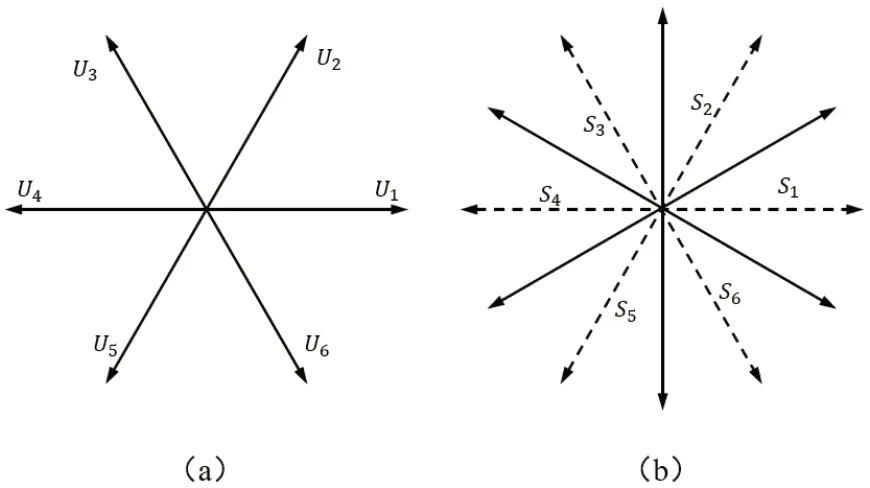
Figure 4.(a) Voltage vector diagram (b) Sector distribution diagram
The direction of the stator voltage vector determines the direction of the stator flux increase.Inputting different voltage vectors can make the motor flux reach the predetermined trajectory.Taking the angular bisector of two adjacent basic non-zero voltage vectors as the boundary, the space is divided into 6 sectors, as shown in Figure 4(b).Determine the sector where the stator flux vector is located, select different voltage vectors to change the flux amplitude and electromagnetic torque.Take the flux linkage vector in sectoras an example, the rotation direction of the motor is counterclockwise, and the influence of different space voltage vectors on it is shown in the following table.
The flux linkage and torque are compared with the expected value, and the difference is controlled by the hysteresis controller.Record the increase output as 1, and the decrease output as 0.When the difference does not exceed the tolerance value set by the hysteresis controller, the last signal output is used; When the difference exceeds the tolerance value set by the hysteresis controller and the actual value is less than the expected value, the output signal is 1; When the difference exceeds the tolerance value set by the hysteresis controller and the actual value is greater than the expected value, the output signal is 0.According to the influence of the 6 space voltage vectors on the flux linkage and torque in each sector, the optimal switching table of the permanent magnet synchronous motor is established, as shown in the following table.
5.Simulation
According to the principle of three-phase permanent magnet synchronous motor direct torque control, a simulation model is built in the MATLAB/Simulink 2020b environment, as shown in Figure 5.The simulation uses the built-in Simulink three-phase permanent magnet synchronous motor model, and the switching device of the three-phase bridge arm is six insulated gate bipolar transistor.Its parameters are set as follows: DC voltage is 311V, motor rotor type is surface mount type, stator resistanceis 1.2Ω, stator inductanceandisH, rotor fluxis 0.175Wb, the moment of inertia J is.
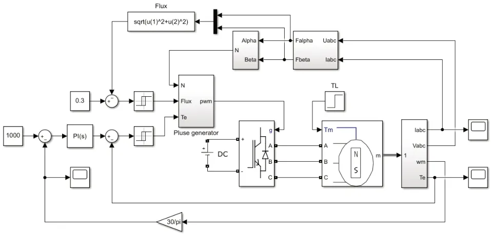
Figure 5.Permanent magnet synchronous motor direct torque control simulation model
In the flux estimation module, the three-phase voltage and three-phase current of the permanent magnet synchronous motor are transformed into the voltage and current in the rectangular coordinate system, and the α and β components of the flux linkage vector are calculated and output according to formula (5).The flux estimation module is shown in Figure 6.

Figure 6.Flux link estimation module
Table 1.The influence of different space voltage vectors on the flux linkage in sector

Table 1.The influence of different space voltage vectors on the flux linkage in sector
Basic voltage vector images/BZ_9_847_382_893_431.pngimages/BZ_9_1111_382_1157_431.pngimages/BZ_9_1358_382_1404_431.pngimages/BZ_9_1604_382_1651_431.pngimages/BZ_9_1851_382_1897_431.pngimages/BZ_9_2098_382_2144_431.pngInfluence on the amplitude of the flux linkage Dramatic increase Increase Decrease Sharp decrease Decrease Increase Influence on electromagnetic torque Increase Decrease Decrease Decrease

Table 2.PMSM traditional direct torque control optimal switch table
According to the composite signal composed of the α and β components of the flux linkage vector, the phase angle of the composite signal is calculated to output the angle of the flux linkage vector and determine the sector where the flux linkage vector is located.The sector determination module is shown in Figure 7.

Figure 7.Sector Judgment Module
The calculated sector and the flux linkage and torque after hysteresis control are input to the pulse width signal modulation module, and six PWM signals are generated according to the traditional direct torque control optimal switch table to control the IGBT of the three-phase bridge arm.Pulse width signal modulation module is shown in Figure 8.
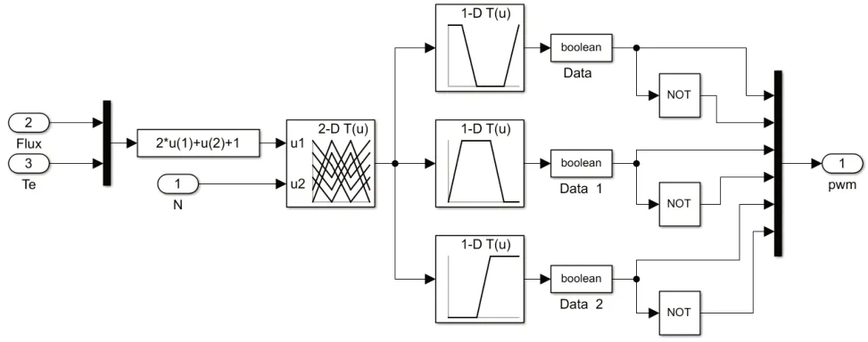
Figure 8.Pulse width signal modulation module
The simulation configuration uses the fixed-step ode23tb algorithm, the fixed-step size is, and the simulation time is 1s.The motor speed is set to 1000rpm, the expected value of the stator flux linkage is 0.3Wb, and a load torque of 10Nm is suddenly added at 0.5s.The simulation result of the direct torque control of the threephase permanent magnet synchronous motor is shown in Figure 9.
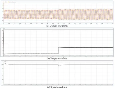
Figure 9.Permanent magnet synchronous motor direct torque control simulation results
6.Conclusions
From the analysis of the simulation results, although the direct torque control has a certain overshoot in the speed and torque at the beginning, it still has a good dynamic response performance, which can meet the needs of motor control performance.However, in the actual motor operation process, the traditional direct torque control has many problems.For example, it is difficult to accurately control under low-speed conditions, the switching frequency of the inverter is not constant, the larger flux linkage and torque ripple and the high-frequency noise caused by it, etc.In response to these problems, its control process needs to be optimized.For example, the voltage vector is subdivided and the zero-voltage vector added to the switch table, using the method of space voltage vector modulation, introduce sliding mode control, fuzzy control, etc.into traditional direct torque control, in order to solve various problems existing in traditional direct torque control, make its control more precise, run more efficient, and more robust.
 Modern Electronic Technology2021年2期
- Modern Electronic Technology的其它文章
- A 4-element Rectangular Microstrip Patch Antenna Array
- Overview of Vehicle AEB
- A Review of Traffic Conflict Avoidance Methods at Intersection Using Vehicle-Infrastructure Cooperation System
- Design of a Submarine Pipeline Inspection Robot System Based on CT Technology
- Research on Thermal Management Control Strategy of Electric Vehicle Liquid Cooling Battery Pack
