Magnetic properties and resistivity of a 2:17-type SmCo magnet doped with ZrO2*
Qi-Qi Yang(杨棋棋) Zhuang Liu(刘壮) Chao-Yue Zhang(张超越) Hai-Chen Wu(吴海辰)Xiao-Lei Gao(高晓磊) Yi-Long Ma(马毅龙) Ren-Jie Chen(陈仁杰) and A-Ru Yan(闫阿儒)
1Laboratory of Rare-Earth Magnetic Functional Materials,Ningbo Institute of Material Technology and Engineering,Chinese Academy of Sciences,Ningbo 315201,China
2College of Metallurgy and Materials Engineering,Chongqing University of Science and Technology,Chongqing 401331,China
Keywords: 2:17-type SmCo magnets,resistivity,coercivity,cellular structure
1. Introduction
The 2:17-type SmCo magnets still play an irreplaceable role in rare-earth permanent-magnet materials due to their excellent high-temperature magnetic properties and corrosion resistance,and they are widely used in electric vehicles and nuclear magnetic energy.[1-4]Nowadays,continuous application development requires SmCo magnets to possess higher resistivity,but,in fact,the resistivity is generally lower.This causes eddy current losses and demagnetization in magnets, which lead to energy waste and unnecessary economic losses.Therefore,the application of 2:17-type SmCo magnets in alternating current fields,such as microwave devices,pot motors and military equipment has been severely limited.[5,6]Over the years,much attention has been devoted to improving the resistivity,however,it remains a challenge.[6,7]
In essence, when a directional moving electron encounters an obstacle in its path, it will scatter, which causes the resistivity to rise. These obstacles include grain boundaries, dislocations, vacancies, and some high-resistivity second phases.[8]Previous works demonstrated that the addition of insulating materials can significantly hinder the movement of electrons, thus increasing the resistivity. However, in this case, the magnet sacrifices a great deal of its magnetic properties, and the operating temperature of the magnet is limited by the melting point of the insulating material.[5,9]Doping with high-resistivity oxides is another way to enhance the resistivity. According to a report by Yi,[10]high resistivity(1000 μΩ·cm) was achieved by doping B2O3into SmCo magnets, but the remanence was only 5.85 kGs. To address this problem, Chinset al.[11]constructed a layered structure of Sm2S3with high resistivity in a 2:17-type SmCo magnet,which exhibited a great leap in resistivity(1845 μΩ·cm)and maintained its magnetic properties. Unfortunately,the Sm2S3layer increased the resistivity along thec-axis,but did not improve it along the direction perpendicular to thec-axis. In addition, the preparation process was complex and difficult.Therefore,more effective methods need to be explored to further improve the resistivity of 2:17-type SmCo magnets.
Alternatively,as a high-melting-point and high-resistance material, ZrO2has been extensively investigated due to its application in oxygen sensors and electrode diaphragms.[12]Its insulating properties[13,14]and the absence of additional impurity elements make ZrO2an ideal dopant material.In our work, the dual-alloy method is used to prepare 2:17-type SmCo magnets doped with different ZrO2contents, which could improve the distribution of particles in mixed magnets.[15,16]The resistivity difference between the two directions decreases, which means that the resistive anisotropism is reduced. A significant enhancement of the coercivity was also achieved. The features of the microstructure and the phase constitution of the magnet doped with ZrO2were characterized by TEM.The relationship between the resistivity and the microstructure was further analyzed.
2. Material and methods
An alloy ingot with a nominal composition of Sm(CobalFe0.23Cu0.07Zr0.03)7.75was prepared through induction melting. The compensation amount was increased by 1.5 wt.%due to the volatilization of the Sm element. The ingot was broken into coarse particles and ground by jet-milling technology to prepare a fine powder with an average particle size of 3.5 μm. ZrO2was doped into the magnetic powder at mass percentages of 0 wt.%, 0.5 wt.%, 1 wt.%, 1.5 wt.%,and 2 wt.%, respectively. After the powders were uniformly mixed, the mixture was oriented in a magnetic field of 2 T and then isostatically compacted. After isostatic pressing at a pressure of 150 MPa, the compacted green magnet was sintered at 1210°C for 0.5 h to densify it, followed by a solution treatment at 1190°C for 3 h. Isothermal aging at 830°C for 12 hours was then followed by cooling to 400°C at 0.7°C/min and the sample was kept at that temperature for four hours.Finally,it was quickly cooled to room temperature.
The demagnetization curves were obtained using a pulsed-field magnetometer (PFM). The resistivity was measured by a physical property measurement system(PPMS-9).The size of the resistivity sample wasa×b×c=2 mm×2 mm×7 mm. The phase constitution was identified by an x-ray diffractometer(XRD)(Phillips)using CuKαradiation.The phase distribution was examined by a field emission scanning electron microscope(FE-SEM).Characterizations of the microstructure and the microchemistry were obtained using a Talos F200X transmission electron microscope(TEM).
3. Results and discussion
Doping with ZrO2improves the coercivity of 2:17-type SmCo magnets. Figure 1 shows the demagnetization curves and the magnetic properties of the Sm(CobalFe0.23Cu0.07Zr0.03)7.75magnets doped with different contents of ZrO2. From the demagnetization curves in Fig. 1(a), it can be seen that the coercivity (Hcj) increases markedly from 30.38 kOe to 37.04 kOe with 1 wt.%of ZrO2dopant,which is about a 21.9%increase. However,the remanence (Br) and the high maximum-energy product [(BH)max]decrease as the dopant content increases, as can be seen in Fig. 1(b). Table 1 shows the corresponding magnetic properties of each component magnet. In addition, the waist and the squareness of the curves gradually deteriorate. SinceHcjkeeps increasing at 1 wt.% and decreases at 1.5 wt.%, those two samples are mainly discussed in the following to find out the reasons for the increase and deterioration ofHcj. On the basis of the increase in the coercivity of the magnet,if a resistivity improvement can be achieved,it may provide a valuable reference for the further development of high-resistivity rareearth permanent magnets.
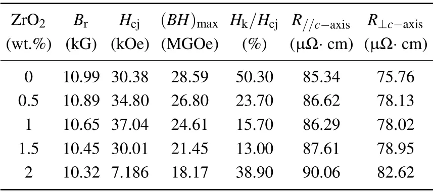
Table 1. Resistivity and magnetic properties of Sm(CobalFe0.23Cu0.07Zr0.03)7.75 magnets with different amounts of ZrO2 dopant.
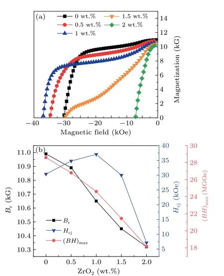
Fig. 1. Demagnetization curves (a) and magnetic properties (b) of Sm(CobalFe0.23Cu0.07Zr0.03)7.75 magnets doped with different ZrO2 contents.
In order to explore the enhancement of magnet resistivity due to doping it with the high-resistivity oxide ZrO2, the above samples were tested, as shown in Fig. 2. The resistivity in the direction parallel to thec-axis is higher than that in the direction perpendicular to thec-axis,which means that the resistivity exhibits anisotropy(it is different in different directions). According to the multi-point fitting curves (the dotted lines),the resistivity shows an upward trend with increasing ZrO2content. Although the maximum resistivity appears when the doping amount is 2 wt.%,the magnetic properties are unacceptable. In any case, when the magnetic properties are guaranteed, the resistivity increases at the doping amount of 1 wt.%. The corresponding resistivity values at each point are shown in Table 1.In order to avoid data fluctuations caused by instrument error and the particularity of the sample’s location,all the resistivity values shown are from the processed data of four parallel samples. We process the data by removing the maximum and minimum values and then calculate the average value of the resistivity from the remaining two samples.To study the mechanism by which ZrO2enhances the resistivity and the coercivity,it is necessary to characterize the phase composition and microstructure of the sample.
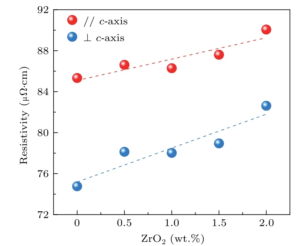
Fig.2. Resistivity of Sm(CobalFe0.23Cu0.07Zr0.03)7.75 magnets with different ZrO2 contents in the directions parallel and perpendicular to the c-axis.
In order to clarify the phase composition, the XRD patterns and FE-SEM images are displayed in Fig.3. The XRD results indicate that the 2:17R phase and the 1:5H phase coexist in the original sample. The peak of the Zr6(CoFe)23phase obviously appears in the ZrO2-doped magnets. The SEM results in Figs.2(b)-2(c)show that the grain boundaries increase significantly,which results in an improvement of the resistivity due to an increase in electron scattering. Based on the EDS point results in Table 2, the three phases shown as dark,grey,and white are Zr6(CoFe)23,Sm2O3,and the matrix phase, respectively. In fact, Sm2O3seems to help in improving the resistivity in other systems, according to a report by Ahmadiet al.[17]Combined with the results, it is reasonable to think that Sm2O3can help improve the resistivity in 2:17-type SmCo magnets. However,Zr6(CoFe)23is a soft magnetic phase,[18]and Sm2O3is a non-magnetic phase. The increase of Zr6(CoFe)23and Sm2O3causes the local pinning strength to weaken,thus creating a step in the demagnetization curves.

Table 2. EDS results for each phase in the magnet doped with 1 wt.%of ZrO2.
The microstructures of the magnets are shown in Fig. 4.The 2:17-type SmCo magnets possess different characteristics in the directions perpendicular and parallel to thec-axis,which lead to different effects on electron scattering. Figures 4(a)-4(c) show the lamellar structures and the rhomboid cellular structure in the direction parallel to thec-axis. Combined with the statistical data in Fig. 4(d), the lamellar phase densities are 0.0538 nm-1, 0.0432 nm-1, and 0.0387 nm-1, respectively, which indicate that the number of lamellar phases gradually decreases with an increase of ZrO2. From the multipoint fitting curve in Fig. 4(e), it can be seen that the resistivity difference between two directions decreases, which means that the resistive anisotropism is reduced. According to Liet al.,[19]the presence of lamellar phases results in the resistivity in the direction parallel to thec-axis being higher than that in the direction perpendicular to thec-axis. In this case,the resistivity gap between the two directions is narrowed due to a reduction of the lamellar phases that block electron movement (Fig. 4(f)). Maximizing the elimination of resistive anisotropism helps to increase the overall resistivity of the magnet. Consequently,it can be considered doping with ZrO2is beneficial in reducing the resistive anisotropism in 2:17-type SmCo magnets.
The microstructure in the plane perpendicular to thecaxis is shown in Fig. 5. As can be seen, the original sample possess a typical cellular structure and continuous cellular boundaries. When doped with 1 wt.% ZrO2, the cellular boundaries remain continuous. However,the cellular structure becomes uneven and the cellular boundaries are discontinuous in the sample doped with 1.5 wt.% of ZrO2. According to the statistical data in Fig. 5(d), the average cellular sizes of the corresponding magnets are 80.04 nm, 107.72 nm, and 132.34 nm,respectively.The statistical results suggest that the cellular structure has grown.The uneven cellular structure and the discontinuous cellular boundaries make the pinning field distribution extremely uneven. In addition,combined with the abovementioned SEM results,it can be concluded that the deterioration of squareness results from the weakening of the local pinning strength and the unevenness of the pinning field.
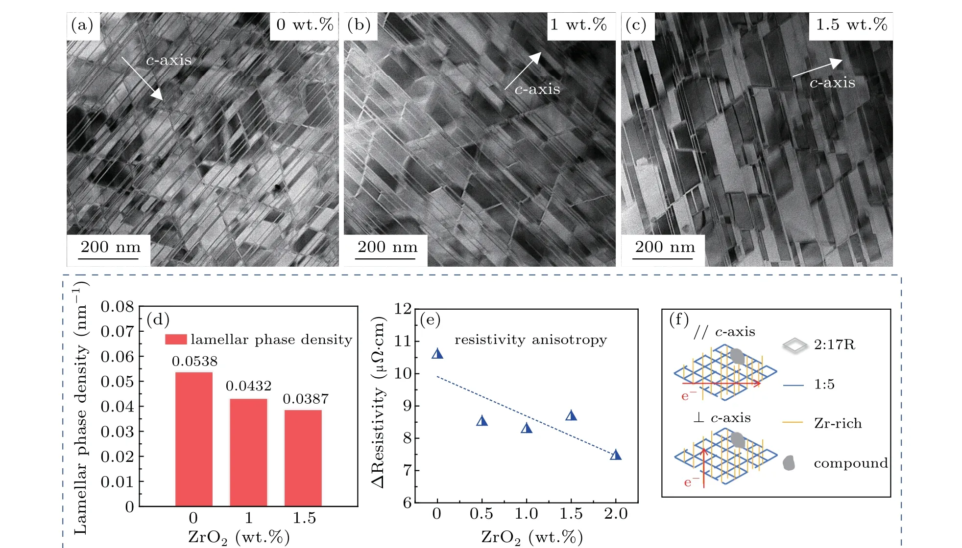
Fig.4. TEM images of magnets with different ZrO2 contents;the plane parallel to the c-axis(a)0.5 wt.%,(b)1 wt.%,(c)1.5 wt.%;(d)density statistics for the lamellar phase; (e) resistivity difference between the directions parallel and perpendicular to the c-axis. (f) Illustration of electrons traveling through the magnet in the corresponding directions.

Fig.5. TEM images of magnets with different ZrO2 contents;the plane perpendicular to the c-axis: (a)0.5 wt.%,(b)1 wt.%,(c)1.5 wt.%;the corresponding statistical distributions(d)of cellular structure size.
Even so, the 1 wt.% ZrO2doped magnet exhibits a markedHcjenhancement. The Cu concentration at the cellular boundary has been deemed to be the key factor in theHcjenhancement.[20,21]Figure 6 shows the statistics for the Cu concentration in the two types of magnet; the average Cu concentration of the cellular boundary in the doped magnet(1 wt.% ZrO2) is 39.60 at.%, which is 7.06 at.% higher than that of the original magnet. As we know,a higher Cu concentration at the cellular boundary results in lower domain wall energy and a lower anisotropic constantK1.[22]According to the pinning model,[23]the magnetic domain walls tend to be pinned at the cellular boundary,where the domain wall energy is lower. Thus,the 1 wt.%doped magnet provides a stronger pinning effect,and exhibits an enhancement inHcj.
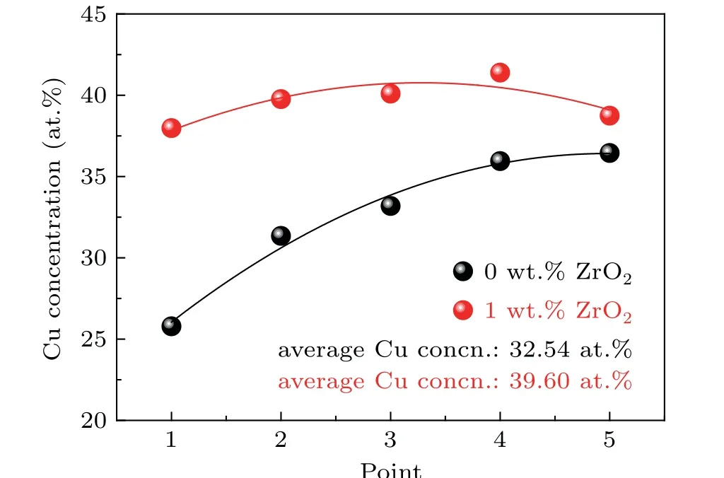
Fig. 6. Cu concentration statistics in the cellular boundaries of the original magnet and the doped magnet.
4. Conclusion
In summary, doping with ZrO2can improve the resistivity of 2:17-type SmCo magnets. Meanwhile, theHcjof magnets can be enhanced by up to 6.66 kOe. The difference in resistivity in the directions perpendicular and parallel to thecaxis is further reduced with increasing ZrO2. The decrease of the lamellar phases leads to a narrowing of the resistive anisotropism. The improvement of resistivity is due to the increase in grain boundaries and the Sm2O3phase,which leads to an enhancement of electron scattering. The higher Cu concentration of the cellular boundaries is the main cause of the enhancement ofHcj.Adding excess ZrO2promotes the precipitation of the Zr6(FeCo)23phase and abnormal growth of the cellular structure,which both result in a decrease of coercivity.
- Chinese Physics B的其它文章
- Projective representation of D6 group in twisted bilayer graphene*
- Bilayer twisting as a mean to isolate connected flat bands in a kagome lattice through Wigner crystallization*
- Magnon bands in twisted bilayer honeycomb quantum magnets*
- Faraday rotations,ellipticity,and circular dichroism in magneto-optical spectrum of moir´e superlattices*
- Nonlocal advantage of quantum coherence and entanglement of two spins under intrinsic decoherence*
- Universal quantum control based on parametric modulation in superconducting circuits*

