Integrated superconducting circuit for qubit and resonator protection*
Xiao-Pei Yang(杨晓沛), Zhi-Kun Han(韩志坤), Shu-Qing Song(宋树清), Wen Zheng(郑文),Dong Lan(兰栋), Xin-Sheng Tan(谭新生), and Yang Yu(于扬)
National Laboratory of Solid State Microstructures,School of Physics,Nanjing University,Nanjing 210093,China
Keywords: interference,decay suppression,Purcell filter
1. Introduction
According to the Jaynes-Cummings model, one can obtain the qubit state by the frequency shift of the coupled resonator.[1]This standard dispersive measurement method has been applied to many systems such as superconducting circuits,quantum dots,and cold atoms.[2-5]One may increase the coupling strength between the qubit and the resonator to improve the qubit state distinguishability. However, it comes with more spontaneous emission of the qubit. The decay loss arising from the Purcell effect will reduce the qubit coherence time,degrading the gate fidelity.[6]Improving the qubit decoherence by either reducing the coupling strength or minimizing the resonator decay rate leads to lower discrimination or readout speed. To solve the conflict and enhance the measurement efficiency, researchers proposed techniques based on parametric amplifiers,Purcell filters,and tunable coupling design.[7-12]
Recently, quantum interference between different paths attracts much attention. The constructive (destructive) interference can enhance (suppress) the transmission. Depending on the coupling regime, the electromagnetically induced transparency (EIT) or Fano resonance leads to the symmetric or asymmetric profiles,which has applications in quantum sensing.[13-15]Among these implementation schemes of interferometry,superconducting circuits possess the advantages of integration and design flexibility. It has shown that the interference can protect qubits from decoherence, resulting in an expandable quantum network.[16]However,these interference effects have not been applied to suppress the qubit decay losses via the resonator.
In this paper, we propose an integrated circuit that protects the superconducting resonator or qubit from decoherence. Based on the usual qubit measuring system, we insert a second lossy resonator into the waveguide. The constructive or destructive interference between the resonators decides the effective decay rate of the readout one.The spontaneous emission of qubits is related to its coupled environment. Here we demonstrate how to control it by arranging the second lossy resonator. This scalable design provides a tool to realize noisy intermediate-scale quantum computing.
2. Purcell effect
We show the schematic diagram circuit in Fig.1. Firstly,we neglect the lossy resonator and consider the Transmon qubit as a two-level system.[17,18]The Hamiltonian of the qubit-resonator interaction system is(¯h=1)

Whenδr1,q=ωr1-ωq ≫g, the interaction system is in the dispersive regime.[19]We can obtain the qubit state by the frequency shift of the readout resonator. For example, when the qubit goes from the ground to an excited state, the resonator frequency changes by 2χ=2g2/δr1,q. The qubit decay known as the Purcell effect isγ ≈κ1g2/δ2r1,q.[6]From the expression ofχandγ,we find that a largerδr1,qcorresponds to a lower qubit decay loss. However, this method reduces the measurement sensitivity. To solve this problem,we can insert a lossy resonator between the readout one and the waveguide.It is known as the Purcell filter,[8-10]which changes the qubit coupled environment and isolates the qubit from decoherence channels.
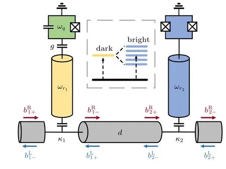
Fig. 1. The schematic circuit design. The left part consists of a superconducting qubit(green)coupled to a readout resonator(yellow). The right part is a tunable lossy resonator(blue)containing a λ/4 resonator and a SQUID.The resonate frequencies of the qubit,readout resonator,lossy resonator are ωq, ωr1, and ωr2, respectively. The waveguide at the bottom connects two resonators. The coupling strength between the resonators and waveguide is κn,n=1,2,respectively;κ1 ≪κ2.The distance between the two resonators is d. Inset: the readout resonator acts as the discrete ‘dark’ mode, and the lossy resonator acts as the continuum ‘bright’ mode. The interference between them will change the transmission spectra of the discrete one.
3. Interference between resonators
Inspired by the Purcell filter design, we investigate the waveguide-mediated interaction between distant resonators.We want to find a configuration that protects the qubit or resonator from decoherence. The Hamiltonian of this system is(¯h=1)
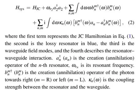
We neglect the qubit and explore the interference between the resonators.When this system works in the Markov regime,the equation of motion for then-th resonator is[20-22]

whereφ=k(ω)d=ωd/vis the phase difference arising from the resonator separation,k(ω) describes the dispersion relation of the waveguide,andvis the speed of the microwave in this device. Inserting Eqs.(4)and(5)to Eq.(3),we can obtain
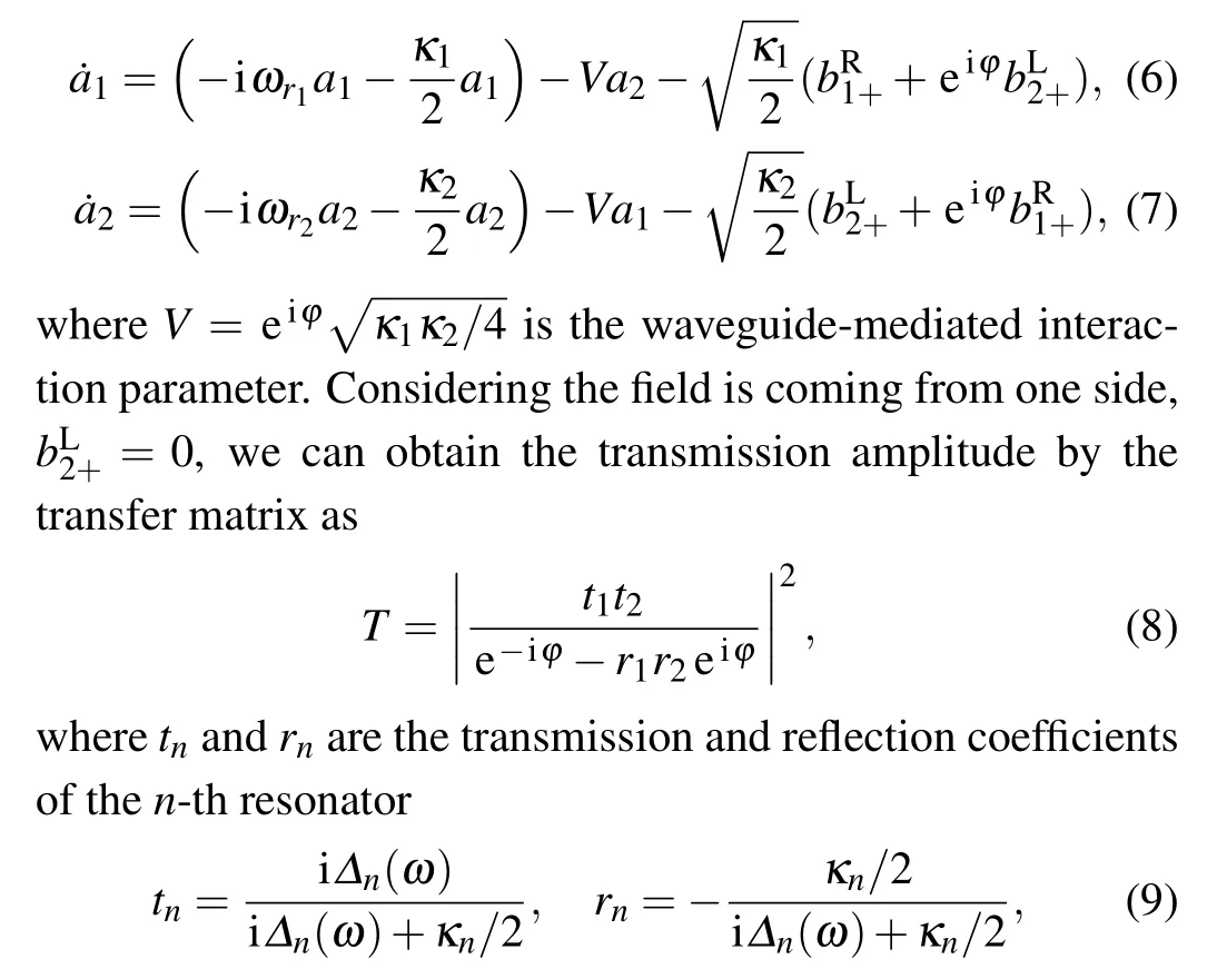
whereΔn(ω)=ωrn-ωis the frequency detuning between then-th resonatorωrnand the probe fieldω.
When the frequency detuning between the resonators,δr2,r1=ωr2-ωr1, is within the line width of the lossy oneκ2, the transmission amplitude in Eq. (8) with differentdis shown in Fig.2(a). The waveguide-mediated interaction arising fromVcan be real,imaginary,and complex. It determines the line shape symmetry of the readout resonator,as shown in Fig.2(b). In experiments,we can fit the transmission curve by the Fano formula

whereF0andHare constant factors,qdetermines the curve asymmetry,ω0is the discrete state frequency,andΓis the resonance linewidth.[14,15]Here,we extend Fano’s theory to our system, and the variation of the readout resonator line shape comes from the interference between a discrete state and a continuum state(see inset in Fig.1).

Fig.2. (a)The transmission spectra of two resoantors with different separation distance d. ωr2 =6.6 GHz. (b)Zoom image of the readout resonator at 6.5 GHz. (c) The transmission around the readout resonator with different δr2,r1 and d =0. (d) The transmission around the readout resonator with different δr2,r1 and d=0.25λr1. The other parameters are ωr1 =6.5 GHz,κ1 =1 MHz, κ2 =100 MHz, and d =mλr1. Here λr1 is the wavelength corresponding to ωr1.
After the device fabrication,we can only controlδr2,r1by the external magnetic field. In practice,we show the transmission spectrums as a function ofδr2,r1with fixedd.For the case ofd=0[see Fig.2(c)],the lineshape of the readout resonator becomes asymmetric. It is getting sharper asδr2,r1decreases.The perfect transmission pointsT ≈1 locate between the two resonant frequencies.For the case ofd=λr1/4[see Fig.2(d)],the readout resonator linewidth is getting broader,and there is no perfect transmission point.
4. Effective decay rate
From Eq. (10) and Fig. 2(b), we find that the line shape and bandwidth(decay rate)of the readout resonatorΓr1are related to the interference effect. In this section, we provide a theoretical analysis ofΓr1, as well as the effective decay rate of the qubitΓq.
The basis of our system is|lmn〉,wherel,m,ncorrespond to the qubit,the readout resonator,and the lossy resonator,respectively. In the single-excitation subspace,the master equation of this system is ˙ρ=-i[Hsys,ρ] and the evolution of the decaying wavefunction is|ψ(t)〉=cq(t)|e〉+cr1(t)|r1〉+cr2(t)|r2〉, where|e〉,|r1〉, and|r2〉represent the bare states|e00〉,|010〉, and|001〉, respectively.cq,cr1, andcr2are the probability amplitudes of the qubit,the readout resoantor,and the lossy resonator

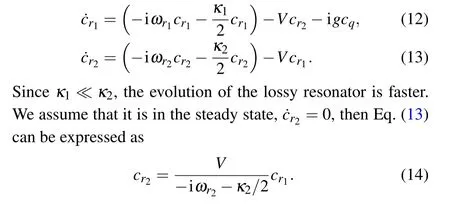
Insert Eq.(14)to Eq.(12)and ignore the qubit-resonator interaction term-igcq,we can obtain the new probability amplitudes of the readout resonator. The imaginary part represents the frequency shift arising from the waveguide-mediated interaction,and the real part decides the effective decay rate of the readout resonator. Under the rotating wave approximation,we arrive at

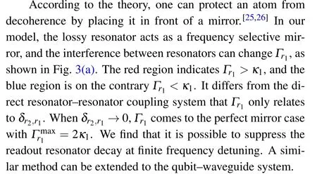
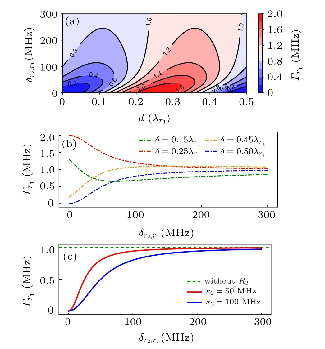
Fig. 3. (a) and (b) The effective decay rate of the readout resonator as a function of δr2,r1 and d=mλr1. Here λr1 is the wavelength corresponding to ωr1. κ2=100 MHz. (c)The effective decay rate of the readout resonator with different κ2 and δr2,r1 at d=0. The other parameters are κ1=1 MHz and ωr1 =6.5 GHz.
In practice, we can changeωr2by the external magnetic field, as shown in Fig. 3(b). HereΓr1is a function ofδr2,r1with fixedd,and this method has application in quantum storage. To reduce the inevitable fluctuations ofdarising from the fabrication process,we can insert a SQUID to the readout resonator. Tuningωr1andωr2at the same time corresponds to changing the effective distance between the resonators.
In the following,we explore the impact ofκ2on resonator decay suppression. Assumingd=0,Γr1with differentκ2is shown in Fig. 3(c). Whenδr2,r1/=0, we can increaseκ2to reduce the effective decay rate of the readout resonator.
Now we further investigate the effective decay rate of the qubit. Aussuming ˙cr2=0 in Eq.(13)and ˙cr1=0 in Eq.(12),putting the results to ˙cqin Eq.(11),we can obtain the effective decay rate of the qubit as

whereδr1,q=ωr1-ωqis the frequency detuning between the readout resonator and the qubit, andδr2,q=ωr2-ωqis the frequency detuning between the lossy resonator and the qubit.
Just like the interference between resonators, the effective decay rate of the qubitΓqis determined byδr2,qandd,as shown in Fig. 4(a). The red region indicatesΓq >γ, and the blue region is on the contraryΓq <γ,whereγis the qubit decay rate without the lossy resonator. In experiments, we can changeωqandωr2at the same time, and this corresponds to changing the effective distance between them. Whend=0 andδr1,q/=0,as shown in Fig.4(b),a largerκ2corresponds to a better qubit decay suppression. Here the lossy resonator acts as a Purcell filter.
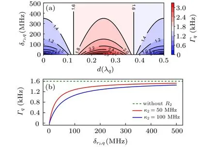
Fig. 4. (a) The effective decay rate of the qubit as a function of δr2,q and d=mλq. Here λq is the wavelength corresponding to ωq. κ2 =100 MHz.(b)The effective decay rate of the qubit with different κ2 and δr2,q at d=0.The other parameters are κ1 =1 MHz, g=20 MHz, ωr1 =6.5 GHz, and ωq =6 GHz. The qubit decay rate is γ ≈κ1g2/δ2r1,q =1.6 kHz when the lossy resonator is absent.
5. Conclusion
In summary,we show the interference effect between distant resonators with different decay rates. The mirror-like lossy resonator provides a tunable boundary condition and can protect the readout one from decay. To improve the coherence time of qubits, we can switch off the decay channel by properly arranging the lossy resonator.
Looking forward,the asymmetric Fano lineshape has application in quantum sensing, and our approach can be extended to the qubit-waveguide system. This integrated circuit has the potential for the quantum information process and quantum control.
- Chinese Physics B的其它文章
- Projective representation of D6 group in twisted bilayer graphene*
- Bilayer twisting as a mean to isolate connected flat bands in a kagome lattice through Wigner crystallization*
- Magnon bands in twisted bilayer honeycomb quantum magnets*
- Faraday rotations,ellipticity,and circular dichroism in magneto-optical spectrum of moir´e superlattices*
- Nonlocal advantage of quantum coherence and entanglement of two spins under intrinsic decoherence*
- Universal quantum control based on parametric modulation in superconducting circuits*

