An active tunable Fano switch in a plasmafilled superlattice array
Tao FU(傅涛),Tianbo YANG(杨天波),Yinbing AN(安银冰),Qi LI(李琦),∗and Zilan DENG(邓子岚)
1 Guangxi Key Laboratory of Precision Navigation Technology and Application,Guilin University of Electronic Technology,Guilin 541004,People’s Republic of China
2 Guangdong Provincial Key Laboratory of Optical Fiber Sensing and Communications,Institute of Photonics Technology,Jinan University,Guangzhou 510632,People’s Republic of China
Abstract We propose a Fano switch arising from the superlattice array of a plasma-filled quartz tube,which can be tuned and reconfigured by the plasma density in the tube.The generation of the switch depends on a Fano band that is induced by the interference between the Mie resonance in an isolated cylinder and Bragg scattering in a periodic array.The underlying dispersion characteristics reveal that a localized tunable flat band corresponding to the Mie resonance plays an important role in the appearance of the Fano resonance.This active tunable switch can be potentially applied to microwave communications as a single-pole multi-throw switch and to monitor environmental variables that impact the plasma density.
Keywords:gaseous plasma,Fano resonance,reconfigurable,tunable,switch
1.Introduction
Plasma,a free electron gas in the bulk domain,generated by discharging a gaseous mixture of argon and mercury[1],is in stark contrast with the surface plasmon that only exists on the interfaces between metallic and dielectric materials[2].The dielectric constant of plasma is actively tunable by varying the plasma density[3,4],which directly determines the plasma frequency[5].This means that plasma-filled tunable devices can be designed without a dependency on changes in geometric parameters.Active and reconfigurable plasma-filled devices have been realized by controlling the physical characteristics of the external magnetic field[6],voltage[7],current[8],gas pressure and other parameters[9].Consequently,plasma photonic crystals(PPCs)have attracted increased research interest in the case of one-,two-and threedimensional systems[3,10–13].Thus far,the PPCs have been used to achieve tunable photonic bandgaps(PBGs)[3,14,15]and introduce peaks in the bandgap[16,17].Recently,Gaoet aldemonstrated a structural tunable PPC in a dielectric barrier discharge by self-organization of the plasma filaments.The plasma structure can be tuned from a square lattice to a triangular lattice by changing the applied voltage[7].Moreover,turning PBGs of one-dimensional photonic crystals on and off by introducing a plasma element has been studied[18].The novel symplectic finite-difference time-domain(SFDTD)has been proposed,which solves the problem of moving PPCs by rewriting the discrete scheme of Maxwell’s equation into a discrete scheme with a velocity variable added[19].For higher permittivity in plasma,the band spectrum is more complicated.Only a part of the frequency bands are periodic bands,while the others are Fano bands with ultrasharp and almost dispersionless features[20].
Fano resonances[21]with asymmetric line characteristics arise generally from the interaction of bright and dark modes in different shapes.This allows their potential application in switching and sensing[22–24].From plasmonic metamaterial to topological system,the Fano resonances in dielectric objects were observed as the interferences between Mie and incident electromagnetic waves[25–28].In recent years,Mie resonances have also generated Fano bands with Bragg scattering in a dielectric periodic array[20],while the Fano bands in gaseous plasma systems have not yet been reported.Most of the tunable switches depend on variation of the geometric parameters or complicated fabrication to achieve the tunability[29–33],which only achieve passive tunability with less flexibility.Therefore,an active tunable Fano resonance would provide a brilliant future for tunable Fano device applications.
In this study,the active tunable Fano switch was achieved by the interference between a narrowband Mie resonance and a broadband Bragg resonance in a gaseous plasma-filled superlattice array.The generation of Fano resonance was controlled by the weakening of Bragg scattering from the simple lattice owing to the lack of some plasma cylinders or reduced plasma density.By contrast,the disappearance of Fano resonance can be achieved by reinforcing Bragg scattering with the reverse approach.The tunability of the Fano switch frequency can be realized by changing the plasma density through the external voltage.The frequencies of the Mie resonance were obtained analytically based on the determination of the Mie scattering coefficient of an isolated plasma cylinder.The transmittances and radar cross-section(RCS)of the individual cylinder confirm the analytical results.Moreover,the photonic band structures and boundary conditions are introduced to explain the mechanism of the Fano resonance generated in the superlattice.Accordingly,the origins of the effect of the plasma density,radius of the plasma cylinder,thickness of the quartz tube,and period of the unit cell were evaluated.
2.Physical model and mechanism of the switch
The top panel of the figure 1(a)represents a schematic of the gaseous plasma discharge and no discharge when the switch is on(the center circle is blue)and off(the center circle is white),respectively.The density of plasma can be controlled by continually adjusting the voltage or current of the discharge because the plasma is generated by the discharge of a mixture of argon and mercury.The greater of voltage or current,the greater the plasma density in the same container.In the bottom panel of figure 1(a),the on and off states of the switch S1 determine whether the gaseous plasma array is simple periodic or superlattice.The commercial software COMSOL Multiphysics 5.3(based on the finite element method)was adopted in this study.The wave vector of the incident wave was along the –y,the periodic boundary condition was along thexdirection and the vector of magnetic field was out-of-plane.The minor mesh length was 0.00375 mm and the frequency step was 0.001 GHz.The default parameters values werer1=1 mm,r2=0.66 mm,p=18 mm,εq=3.8,andne=2×1012cm−3.The red and blue dashed line areas represent the superlattice cells withp=4dandp=2d,respectively.The plasma densities are the same(ne)whenp=4d.The plasma densities of the center cylinder remain unchanged and the others(ne')are tuned by the slide rheostats whenp=2d.Figure 1(b)depicts the Fano resonance frequencies as a function ofp.The Fano resonance disappears when the superlattice array(p>3d)degenerates to a simple lattice[34](p=3d).The Fano resonance frequency shifts toward higher frequencies aspincreases from 10 mm to 11.7 mm(p<3d)indicating that the Fano resonance induced by the Mie resonance is influenced by the strong field coupling between adjacent units.In contrast,the Fano resonance frequency remains almost unchanged whenp>3din figure 1(b).This is because the near-field coupling in the superlattice dominates the Bragg scattering and the weak field coupling between adjacent lattices hardly influences the Fano resonance.
The states of the Fano switch are shown in figure 1(c).The Fano resonance appears at approximately 7.1 GHz when the switch S1 is off.Thus,the active switch can be achieved by setting the switch S1 to the on and off states.The field componentExplots of the on and off states are shown in insets of figure 1(c).These plots demonstrate that the Fano resonance is formed by destructive interference between two dark modes,which requires yield opposite phases and equal electromagnetic waves amplitudes.The electric fields are localized in the bulk-plasma rather than localized around the interface between bulk-plasma and quartz wall,which is explained in the following section.These results show that the Fano resonance can be generated by transforming the simple lattice to a superlattice.Herein,we reveal the mechanism responsible for the Fano resonances with boundary conditions.According to the boundary conditions of the superlattice,the superlattice supports the out-of-phase dark mode in figure 1(c),and there is no phase difference on the two sides of the unit boundaries.When the superlattice degenerates to the simple lattice withp=3d,it is impossible to pick an arbitrary lattice with three cylinders in the simple lattice to fulfill the same phase difference on the opposite boundaries in figure 1(c).Thus,destructive interference will not occur,and the Fano resonance disappears in the simple lattice.Figure 1(d)demonstrates the transmittance curve of the superlattice array(p=2d)which varies as a function of the plasma densityne'.It is clear that the Fano resonance frequency shifts toward higher frequencies with the increase ofne'.The Fano line shapes become wider as the plasma density is far away from 2×1012cm−3.The phenomenon of Fano resonance disappears whenne'=2×1012cm−3.This result is the same as that of the blue curve in figure 1(c)owing to the superlattice transforming to a simple lattice.The electric field distributions of the insets in figure 1(d)prove that the Fano resonance is generated from the interference between two dark modes.The decrease and increase of plasma density will destroy the Bragg scattering in a simple lattice.As a result,the extra resonances and Fano resonance are introduced simultaneously.It is worth mentioning that this Fano resonance can be actively adjusted with a slight density shift ofne'.
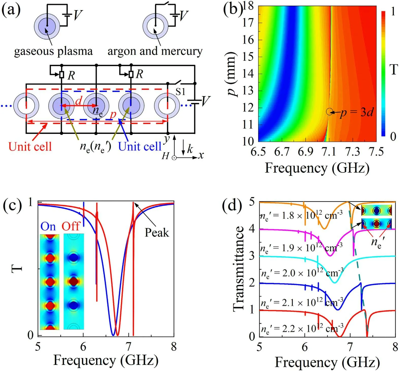
Figure 1.(a)Schematic of the plasma-filled cylinder array with two cases.(b)Transmission spectra of the superlattice array(red‘Unit cell’)varying with the period p from 10.0 mm to 18.0 mm in step of 0.1 mm.(c)The on–off states of active switching.(d)Transmission spectra of the superlattice array(blue ‘Unit cell’)varying with different ne'.
3.Interference in a superlattice
The normal incident transverse electric(TE)plane wave propagated through the trimeric medium with a plasma densityne=2×1012cm−3,periodp=18.0 mm,and a gapd=3.9 mm.Clearly,no Fano resonances have arisen at 7.1 GHz(top part of figure 2(a)).However,in the bottom part of figure 2(a),a Fano resonance is clearly present around the frequency of 7.1 GHz in terms of the asymmetric line shape and the out-of-phase(-+-)dark modes(inset in figure 2(a)).The significant Fano resonance is presented as the coupling between the broadband Bragg scattering and the narrowband Mie resonance.In addition,the resonances of the Mie and Bragg are evidenced at approximately 6.3 GHz with a slight frequency difference that results in the double resonant peak at approximately 6.3 GHz in figure 2(b).The field patterns in figure 2(b)are different from the patterns localized in the center of the plasma cylinders in figure 2(a).Whenω<ωpe(the incident wave frequency always fulfils this condition in this study),the plasma has a negative permittivity as a free electron gas.Moreover,the waves are usually forbidden to propagate owing to the cutoff phenomenon when its frequency is below the plasma frequency.
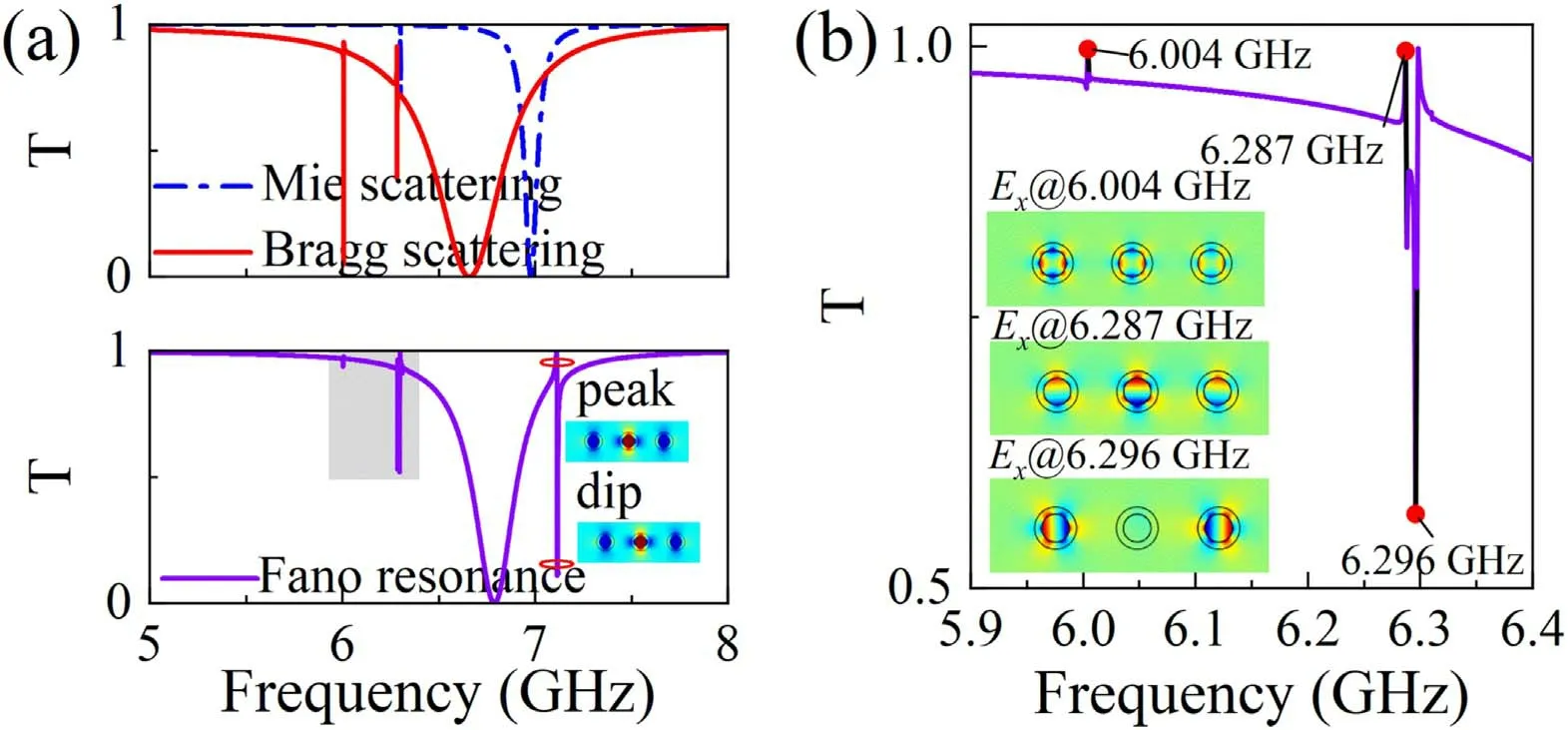
Figure 2.(a)The transmittance curves of Mie scattering,Bragg scattering and Fano resonance.The periods are p=18.0 mm,p=d, and p=3d with d=3.9 mm,respectively.The transmittance and the resonant field pattern for the shaded area are shown in detail in(b).
Furthermore,we mainly focused on the surface plasma waves in this study which resemble the localized surface plasmon polaritons of metal,which decrease the operating frequency of surface plasmon polaritons(SPPs)from the optical to microwave region and localize the EM field around a plasma cylinder[11,12,35].The appearance of the Fano resonance provides a passband in the cutoff area.This results in the localization of the electric field in the bulk-plasma rather than at locations around the interface between the bulkplasma and quartz wall.We can observe the excitation of the dipole–quadrupole and dipole-mediated quadrupole–octupole interferences[36],as demonstrated in the bottom part of the inset in figure 2(b).
In the case of TE waves,the magnetic fieldHzfulfilled the wave equation in the polar coordinate system and the entire space can be classified in three different regions as previously described in reference[37,38],as shown in figure 3(a).Thus,the magnetic field can be described as,
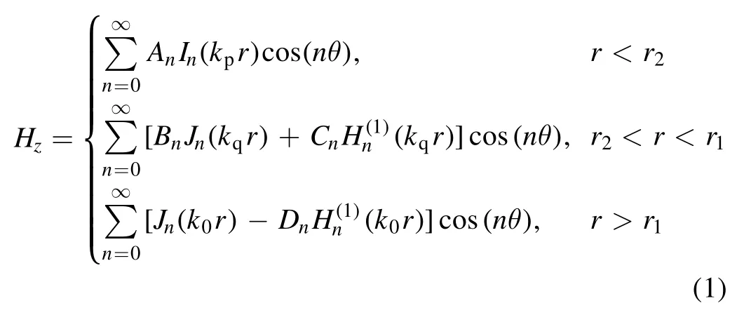
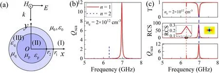
Figure 3.(a)The cross-section of an isolated gaseous plasma-filled cylinder.(b)Analytical solution of Mie scattering at different n values as defined in equation(6).(c)Comparison of resonance frequency with transmittance(top),radar cross section(RCS)(center),and Qsca(bottom)of the single plasma cylinder.
with


and

In this case,k0,kq,andkpdenote the wave vector in the free space,quartz wall and plasma,respectively.The frequencydependent permittivity of plasma is given by the Drude modelwhereis the plasma frequency.
To compare the Mie resonance frequency with the Fano resonance frequency,we calculated the scattering efficiencies[38]that are defined as

Figure 3(b)shows the Mie scattering coefficient with the variousnfor the above equations.The symmetric Lorentz line shape of the resonance peaks obviously manifests the Mie resonant states stimulated at 6.3 GHz and 7.0 GHz.To confirm the analytical results of the Mie resonance,we analyzed the transmittance and the RCS of an isolated plasma-filled cylinder with the same plasma density,as shown in figure 3(c).It is very important to choose the length of the period of the structure to eliminate Bragg scattering between adjacent cells.This must fulfill the condition that there are no significant influences on the Fano line shapes as the period varies.The unchanged line shapes mean that there is no interference between the two adjacent units whenp>3d(from figure 1(b))with three cylinders in a cell.Furthermore,an isolated plasma-filled cylinder in the unit cell with periodp=18.0 mm(p≫3d)must satisfy the condition that achieves the elimination of the Bragg scattering even with the periodic boundary condition along thexaxis.A significant transmission dip illustrates the plane wave that stimulates a resonant mode that corresponds to the lower Mie resonance mode,which means that the Mie resonance in the lower-order mode contributes to the formation of the Fano resonance.The enlarged and the normal RCS lines in the middle of figure 3(c)show that the peak frequencies of RCS are identical withQsca.These numerical results are in good agreement with the analytical solution of the Mie resonance.The inset in figure 3(c)illustrates that the Mie resonance results in the localization of the electric field of the Fano resonance at the center of the plasma cylinder rather than around the plasma cylinder,as shown in figures 2(a)and(b).
4.Band diagrams of the simple lattices and the superlattices
To explain the cause of the generated Fano resonance in the superlattice array,photonic band structures were studied based on COMSOL Multiphysics 5.3.Figure 4(a)shows the photonic band structure(left-half panel)and the transmittance curve(right-half panel)for a unit cell with one plasma cylinder and periodp=3d(this parameter is the same as that of the top panel of figure 3(c)).The field patterns at the red dots prove that the nearby flat band corresponds to the lowerorder Mie resonance.The transmittance yields a typical Lorentz line shape,which indicates that a pure Mie resonant mode is stimulated at a frequency of 6.96 GHz.An asymmetric Fano line is generated only during transmittance by a trimeric superlattice with periodp>3d(d=3.9 mm),as shown in figure 4(b).As the existence of a flat band is believed to be a consequence of destructive interference,opposite phases and equal amplitudes of the EM waves are required[39].Thus,the phases of the Fano resonant field patterns of the three plasma-filled cylinders in figures 4(b)and 1(b)are in antiphase(-+-)and almost have equal amplitudes.Moreover,a broadband mode is one of the two requirements for the presentation of Fano resonances,as illustrated in figure 4(c)with periodp=3d(d=3.9 mm).The flat band and the Fano line shape for the lower-order Mie resonance in figures 4(a)and(b)disappear because superlattice structures degenerate to a simple periodic array.
As described in the Drude model,the dielectric function of the plasma can be varied only by changing the plasma density and incident wave frequency.Therefore,figure 4(d)demonstrates the active tunable photonic flat band,Mie resonance,and Fano resonance,following changes of the plasma density only.It is evident that the resonance frequencies of the three curves shift toward higher frequencies with increasing plasma density.Given that the eigenfrequencies of an isolated plasma cylinder are changed by transforming the plasma density,the Mie resonance frequencies are changed synchronously.Finally,the Fano resonance frequencies are varied in the same way.These results strongly support the fact that the Fano resonances were derived from the coupling between the Mie and Bragg scattering as well as the active tunability achieved by varying the material characteristics(plasma density or dielectric constant)rather than the geometric parameters.The tunable range of Fano resonance by varying plasma density is larger than changing geometric parameters.Figure 4(e)shows the frequency variations of the Mie resonance,Fano resonance and RCS with the increase ofr1in two cases.(a)Fixing the radius of the plasma cylinder,r2unchanged,and(b)fixing the thickness of the quartz tube,r1−r2=0.34 mm unchanged.In both cases,the resonance frequencies of the Fano resonance and RCS are consistent with each other.The existence of the differences between the Mie and the Fano resonances of the two cases arises from the shifts of the scattering boundary conditions.The Mie scattering of an isolated plasma cylinder was calculated in an infinite space without any external disturbance.However,the scattering of a cylinder was influenced by the other two cylinders in the superlattice cell.In case(a),the resonance frequencies decrease owing to the weakening near-field coupling between plasma cylinders asr1increases.The frequency differences between the Fano and Mie resonances are small and stable.This results from the unchanged radius of the plasma cylinders(dominated the near-field coupling),and the thickness of the quartz tube has minor influences on near-field coupling action.In case(b),the resonance frequencies of Mie,Fano and RCS(superlattice)resonances are increased on account of the stronger near-field coupling between plasma cylinders asr2increases.Meanwhile,the frequency differences between the Fano resonance and Mie resonances in case(b)are larger than those in case(a),which is because the coupling is more affected by the increase in the radius of the plasma cylinders than by the increase in the thickness of the quartz tubes.The range of the tunable Fano frequency in case(a)is broader than that in case(b).
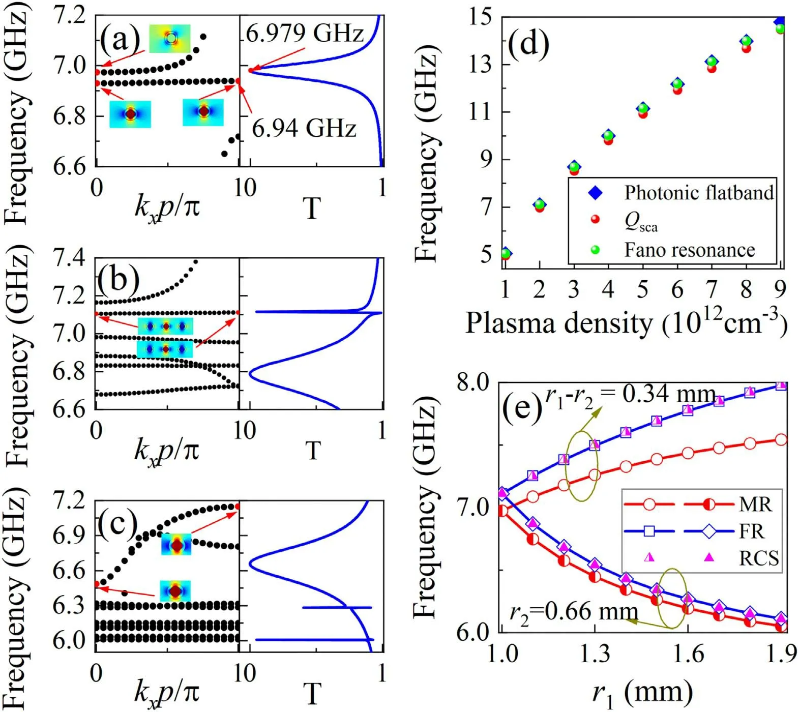
Figure 4.Photonic band structure and transmittance curves for(a)an isolated cylinder with period p,(b)a superlattice array with period p,and(c)a simple period array(d=3.9 mm).(d)The active tunability of Qsca of an isolated plasma cylinder,flat band frequencies of superlattice and the Fano resonance frequency of superlattice by changing plasma density.(e)Mie resonance(MR)frequencies of an isolated plasma cylinder,Fano resonance(FR)frequencies,and RCS of superlattice array as the function of r1 with r1−r2=0.34 mm and r2=0.66 mm.
5.Conclusion
We presented herein an active tunable Fano switch which originated from the interference between the narrowband Mie and broadband Bragg resonances in a gaseous plasma-filled superlattice array.The Mie scattering coefficient of an isolated gaseous plasma-filled cylinder was analyzed to explain the Mie resonance contribution to the generation of the Fano resonance.The photonic band structures demonstrate that the Mie and the Fano resonances corresponded to a photonic flat band.Fano resonance disappeared when the superlattice array degenerated to a simple periodic array because destructive interference cannot occur in a simple periodic array without inducing phase differences.The tunability can be achieved by actively varying the plasma density rather than varying the passive geometric parameters.The frequency differences between the Fano and Mie resonances were attributed to the variation of the scattering boundary condition owing to the changes of the radius of the plasma and the thickness of the quartz tube.The tunability of the Fano switch makes it potentially applicable to microwave communications as a single-pole multi-throw switch and to monitor environmental variables that impact the plasma density.
Acknowledgments
This work was supported by National Natural Science Foundation of China(Nos.11965009,61761010,61765004,61764001 and 62075084)and Natural Science Foundation of Guangxi(Nos.2018JJA170010 and 2018GXNSFAA281193),and by the Guangdong Basic and Applied Basic Research Foundation(No.2020A1515010615).
ORCID iDs
 Plasma Science and Technology2021年7期
- Plasma Science and Technology的其它文章
- Numerical simulation of carbon arc discharge for graphene synthesis without catalyst
- Enhanced removal of ultrafine particles from kerosene combustion using a dielectric barrier discharge reactor packed with porous alumina balls
- Visualization of gold nanoparticles formation in DC plasma-liquid systems
- Rice plant growth and yield:foliar application of plasma activated water
- Comparison of sample temperature effect on femtosecond and nanosecond laser-induced breakdown spectroscopy
- Magnetic field induction and magnetic force distribution profiles in plasma focus discharge device
