
阻氚涂层辐照-渗氢耦合装置的设计
2021-06-03 02:23:06朱昌达冯勇进杨远友廖家莉冯开明杨吉军
四川大学学报(自然科学版) 2021年3期
石 柯, 朱昌达, 张 伟, 王 龙, 冯勇进, 杨远友, 廖家莉, 冯开明, 刘 宁, 杨吉军
(1.四川大学原子核科学技术研究所 辐射物理及技术教育部重点实验室, 成都 610064;2. 核工业西南物理研究院, 成都 610041)
1 Introduction
Tritium permeation barrier (TPB) coating is an important function material to safely handle radioactive tritium and optimize the tritium balance in fusion reactor[1-2]. The working condition of tritium permeation barrier coating in the tritium breeding blanket is complex and harsh, because it has to face the multi field coupling effect of high temperature, neutron irradiation and tritium containing gas medium[3-4]. This service environment requires a TPB coating with very high performance, therefore, the study on the properties of TPB coating is a challenging problem in the field of fusion reactor[5-8].
The characterization of TPB coating properties is the key for the design of the coating preparation technology, which directly affects the development of the coating technologies[9-10]. In previous studies, many researchers usually used the as-deposited coatings to evaluate its performance, such as tritium resistance, mechanical properties, radiation resistance and high temperature stability[11-13]. In fact, the TPB coatings are used under high temperature, tritium containing gas medium and neutron irradiation conditions[3, 10]. The multi-field coupling environment could affect the performance of TPB coatings. Especially, these different physical fields will play synergistic effect in the coating performance. Therefore, the real performance of TPB coating under the multi-field coupling environment could be different from that of the as-deposited coating.
To solve this problem, it is necessary to develop a terminal for the study of the TPB coating properties under multi-field coupling conditions. One of the promising facilities is the so-called “charged particles irradiation-high temperature-hydrogen permeation” multi-fields coupling device, which can test TPB coatings by simulating the real working conditions. Among them, the neutron irradiation damage is simulated by charged particles irradiation, which makes the terminal has several advantages, including non-radioactive, short experimental period, and controllable parameter[14-18]. For example, Munozetal.[15]have developed a new permeation terminal “Radiation Induced Permeation” (RIPER) for the first time in order to obtain relevant data on permeation of hydrogen isotopes in TPB coatings under irradiation. This terminal allows one to differentiate and characterize gas concentration driven permeation, and permeation due to different parameters applied to the sample conditions like temperature, irradiation dose or electric field.
In the present study, a terminal for the study of simultaneous proton irradiation and hydrogen gas permeation for testing TPB coatings at elevated temperature has been developed. The major components and design details of the terminal will be described, including the overall design goal, sample holder design, hydrogen permeation loop design and optimization of the terminal and testing parameters. The terminal provides an advanced experimental platform for studying the TPB coating performance under the multi-field coupling environment.
2 Experimental design
2.1 Overall design goal
Schematic illustration of the simultaneous proton irradiation-hydrogen permeation terminal for TPB coatings is shown in Fig.1. The terminal consists of HVE tandem accelerator, ion beamline, gas control system, heating control system, operating system,etc. The protons in the energy range 1~6 MeV, generated by the 2×3 MV tandem accelerator in Sichuan University, across the vacuum chamber arrived to the sample stage. Meanwhile, the heating gas (H2and He) with a proper temperature filled the sample stage, to create multi-field coupling environment. As shown in Fig. 1, the gas detector captures gas signal if the Ti foil is broken, then the valve will close to protect the accelerator. Infrared thermometer measures the temperature of samples to obtain accurate temperature in real time, the sample stage cools by cooling water. Gas heating system and gas control system guarantee the mix gas at the given temperature and pressure. Moreover, irradiation damage, high temperature and hydrogen permeation happened on the sample stage at the same time. Various experimental conditions can be obtained by controlling the gas flux, gas composition, irradiation dose and energy, heating temperature,etc. The details about the major components will examine later in this paper.

Fig.1 Schematic illustration of the simultaneous proton irradiation-hydrogen permeation terminal for TPB coatings
Fig.2 shows the photos of the tandem accelerator and the simultaneous proton irradiation-hydrogen permeation terminal for TPB coatings. The 2×3 MV tandem accelerator in Sichuan University showing in Fig.2(a) can generate 1~6 MeV stable proton beam. Moreover, the part of yellow box is the sample test terminal. The gas device built by ourselves showing in the right of Fig. 2(b) provides abundant H2and He gas, meanwhile, the sample holder heats the sample to a high temperature. The tandem accelerator, sample holder and gas device hold together to create a multi-field coupling environment for TPB coating tests. The proton beam irradiates the TPB coatings while the He-H mix gas permeating through the TPB coatings, which heat to high temperature by sample holder. In this way, the proton irradiation experiments with high temperature hydrogen permeation are able to achieve on this terminal. These components formed the advanced multi-field coupling experimental platform for TPB coating tests.
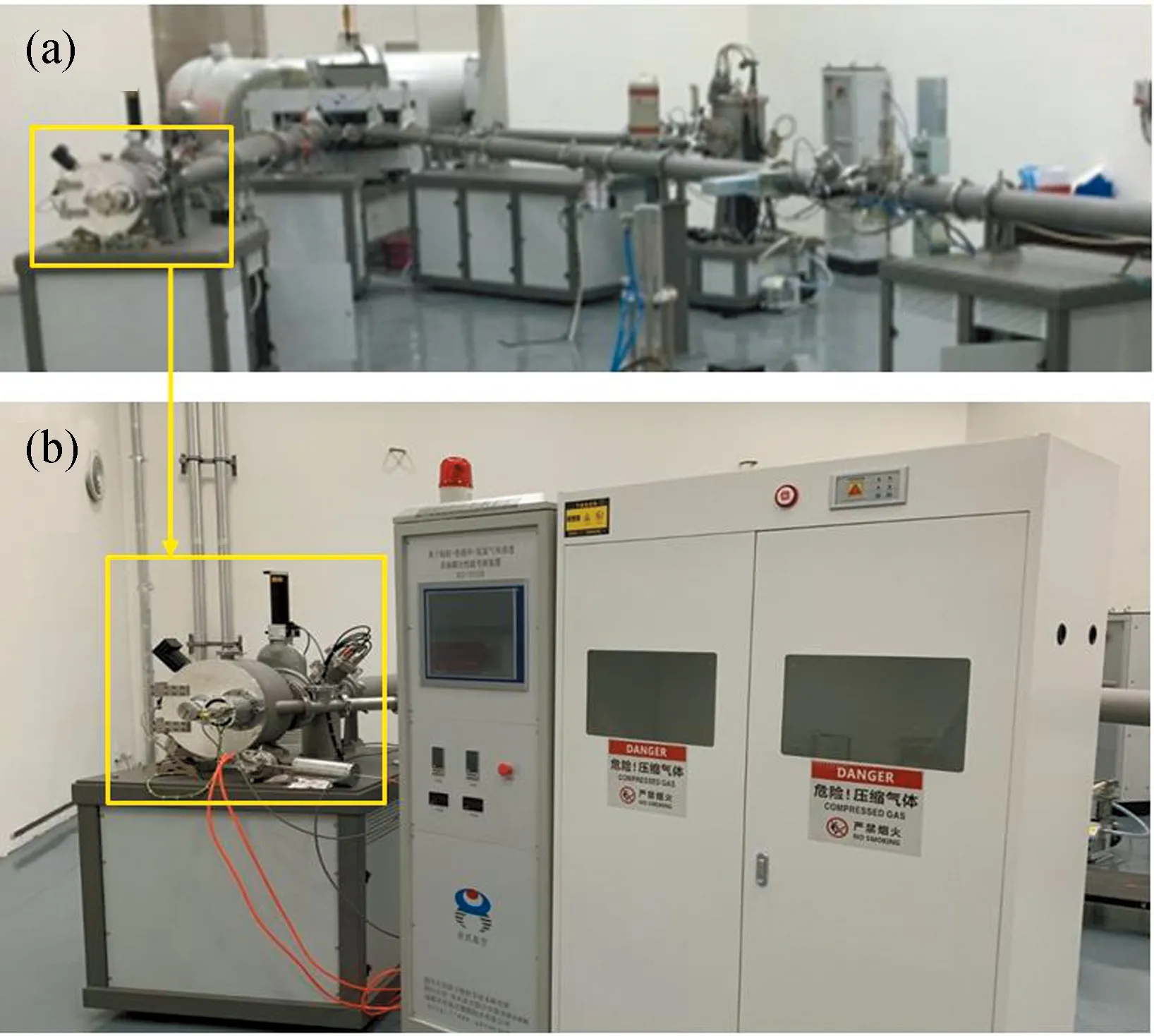
Fig.2 Photos of (a) the HVE tandem accelerator, which irradiation beamline is connected with (b) the simultaneous proton irradiation-hydrogen permeation terminal for TPB coatings
2.2 Sample holder design
Sample holder is the most important partner ensuring the experiment safe and reliable, the schematic illustration of the structural and photo of TPB coating samples holder are shown in Fig. 3. The sample holder is comprised of vacuum boundary, separation foil, high temperature/pressure H2+ He gas, heating components and thermal shield. Heating components can heat the samples from room temperature to 500 ℃,gas pressure can change from 0 to 0.2 MPa by gas control system. The separation foil (titanium as usual) separates the vacuum chamber and gas chamber, to guarantee the proton beam through itself and no gas permeate to vacuum chamber. Ti foil was tested at the pressure up to 0.25 MPa for 72 h to ensure its strength satisfied. High temperature/pressure H2+ He gas simulates hydrogen permeation environment. Meanwhile, the heating components heat the samples to a given temperature. In this way, the TPB coatings are irradiated by proton with hydrogen permeation and high temperature at the same time, creating a multi-field coupling environment.
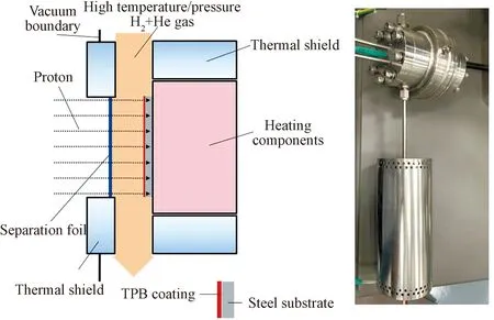
Fig.3 Schematic illustration of the structural and photo of TPB coating samples holder
Fig. 4 shows design principle of the TPB coating samples holder. Using Al2O3coating (20 μm) as an example, Ti foil (30 μm) as the separation foil, 6 MeV proton as incident ion through the thickness of the 500 μm He-H mix gas (density 0.000 178 5 g/cm3), the radiation simulation diagram was obtained by SRIM[19]. About 99 999 protons were carried out to simulate the irradiation process, the proton distribution and penetration depth were verified by TRIM calculations. The number of displacements per atom (dpa) derived from SRIM using expression[20]versus irradiation depth can be found from Fig. 4. Proton beam penetrates the Al2O3coating with uniform damage, and the divergence (breadth of proton beam) is 122 μm. The simulation results indicated that the 6 MeV proton beam passed completely through the Ti foil, He-H mix gas and Al2O3coating with a small beam divergence, which means the Al2O3coating suffering an uniform damage. The maximum penetration depth of proton beam is very close to the peak damage area. The experiment system is demonstrated to be feasible according to the theoretical study. By the way, the testing parameters can be optimized by SRIM before the actual experiments.
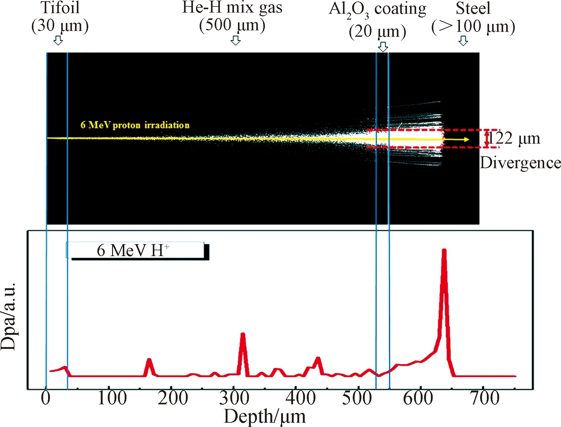
Fig.4 Design principle of the TPB coating samples holder
2.3 Hydrogen permeation loop design
Fig. 5 shows schematic illustration of the hydrogen-containing permeation gas loop, which consists of H2container, He container, gas mixing tank, heating oven, pressure regulator, chiller and exhauster. H2gas and He gas are mixed at gas mixing tank, then heat to a given temperature (room temperature to 500 ℃) by heating oven, using pressure regulator to control gas pressure, obtaining high temperature/pressure H2+ He gas for experiment. The pressure of flowing H2-He mix gas can be changed from 0 to 0.2 MPa according to the experimental requirements. By the way, the gas pressure can achieve a higher standard by changing a thicker Ti foil in some special experimental conditions. H2and He mix gas is always flowing during the whole progress of experiments. The gas control system can simulate different working condition by changing the proportion of H2gas and He gas, the gas temperature and pressure. Finally, the redundant gas cooled by a chiller and discharged to the environment using an exhauster.
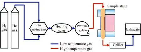
Fig.5 Schematic illustration of the hydrogen-containing permeation gas loop
2.4 Optimization of the terminal and testing parameters
Experimental parameter optimization of the terminal is crucial to ensuring the success of the experiment, and a suitable parameter can make more accurate experiment results. Proton beam penetrativity and divergence with different testing parameters such as proton energy, thickness of Ti foil, thickness of H-He gas, thickness of Al2O3calculated by SRIM are shown in Tab.1. Penetrate (Yes/No) means whether or not the proton beam can pass completely through the Al2O3coating, and Divergence means the breadth of proton beam when pass through the Al2O3coating (see Fig. 4). More details can be found from Fig.6~9.
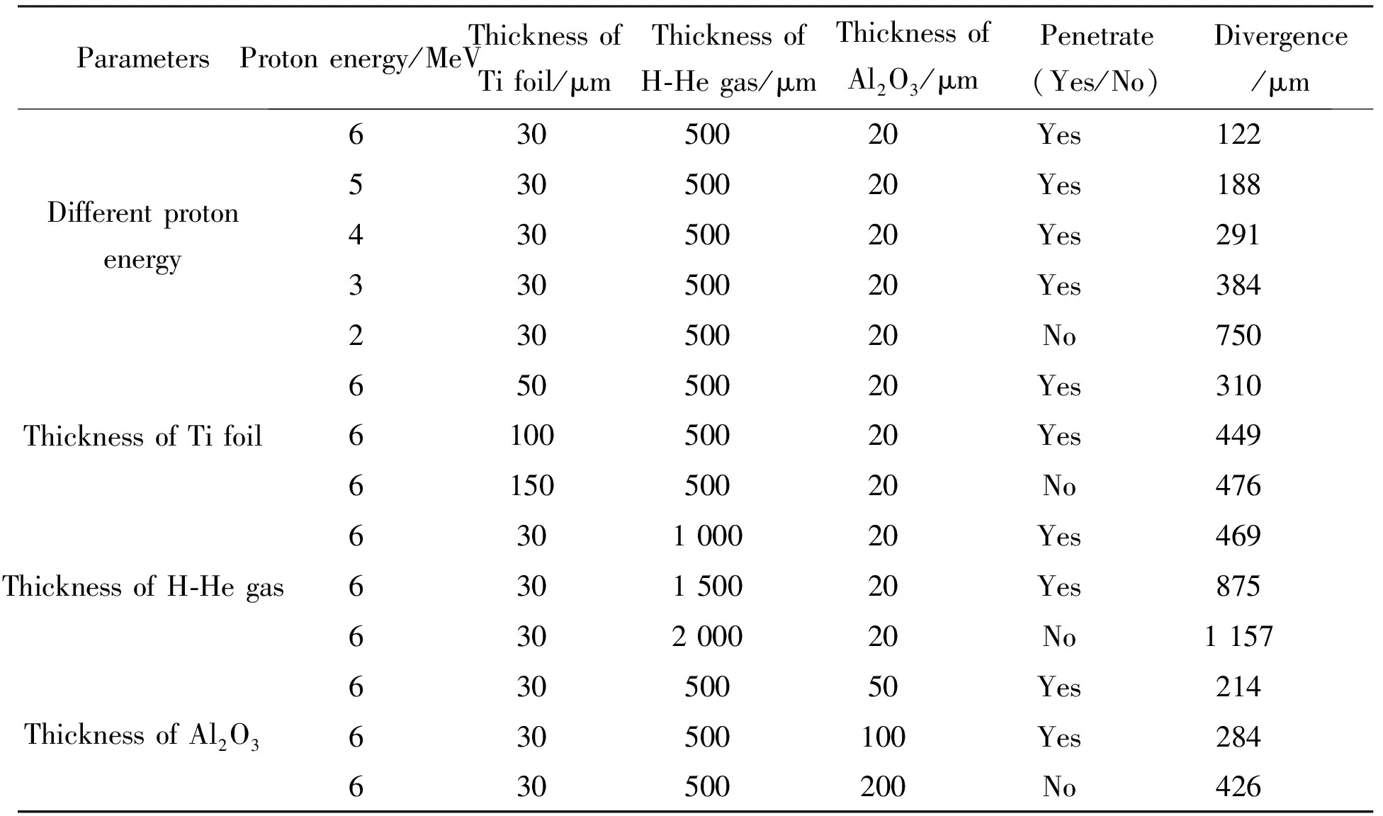
Tab.1 Proton beam penetrativities and divergences with different testing parameters calculated by SRIM
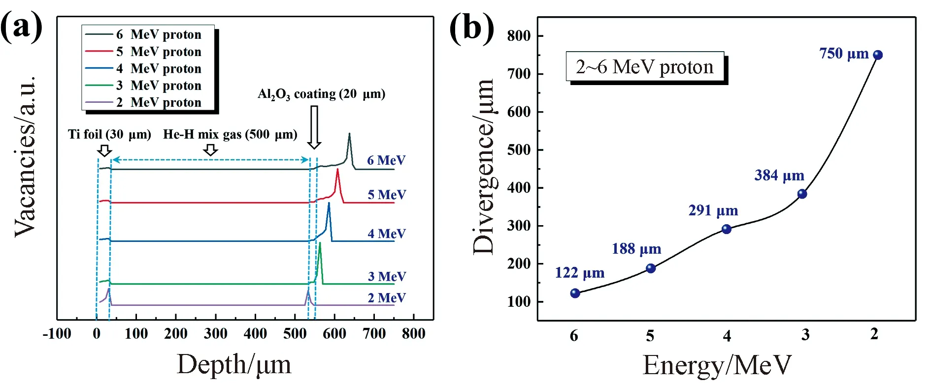
Fig.6 Simulation of (a) vacancies vary with irradiations depth and (b) divergence of proton beam for 2~6 MeV protons incident on TPB coating samples calculated by SRIM software
Proton energy affects the irradiation depth of TPB coatings, a suitable energy is helpful for the experiments. Simulation of vacancies vary with irradiations depth and divergence of proton beam for 2~6 MeV protons incident on TPB coating samples calculated by SRIM software are shown in Fig. 6. Ti foil (30 μm), He-H mix gas (500 μm), Al2O3coating (20 μm), steel matrix (>100 μm) as the simulation parameters remained unchanged, the energy of protons changed from 6 to 2 MeV. The simulation schematic illustration can be found from Fig. 4, the maximum penetration depth of proton beam is very close to the peak damage area. Peaks of vacancies means the peak damage area, therefore, it means the proton beam cannot pass through the Al2O3coating when the coating at the peaks of vacancies.
The results indicated that theprotons pass completely through the Al2O3coating with the energy of 6, 5 and 4 MeV. The proton beam exactly passed the Al2O3coating when the proton energy reduced to 3 MeV, 2 MeV proton beam cannot pass the Al2O3coating by calculation, it is demonstrated that the proton energy should be at least 3 MeV on this setting condition. The smaller divergence means the more uniform irradiation damage for Al2O3coating. Divergence of proton beam increasing with the decreasing irradiation energy from 6 to 2 MeV indicated that high proton energy is contributed to experimental tests. Therefore, the proton energy must be high enough to allow the proton beam to pass completely through the TPB coatings, to guarantee the experiments completed smoothly on this terminal.
Ti foil is the separation foil that separates the He-H mix gas from the vacuum, the Ti foil requires an appropriate thickness to pass through itself entirely with proton beam and guaranteeing the He-H mix gas cannot penetrate it, to ensure the tandem accelerator safe. As shown in Fig. 7, simulation for 6 MeV protons pass through the thickness of the 30, 50, 100 and 150 μm Ti foils (500 μm He-H mix gas, 20 μm Al2O3coating and >100 μm steel matrix remained unchanged) were calculated by SRIM software. Divergence of proton beam increasing with the increasing thickness of Ti foils from 30 to 150 μm. Proton beams penetrated 30, 50 and 100 μm Ti foils successfully and passed completely through the Al2O3coating. The proton beams were obviously divergence with the thickness of Ti foil up to 100 and 150 μm, in addition, the proton beam partly passed the Al2O3coating when the thickness of Ti foil up to 150 μm. Therefore, the thickness of Ti foil should be less than 150 μm in principle and as thin as possible, to guarantee the experiments completed smoothly on this terminal.
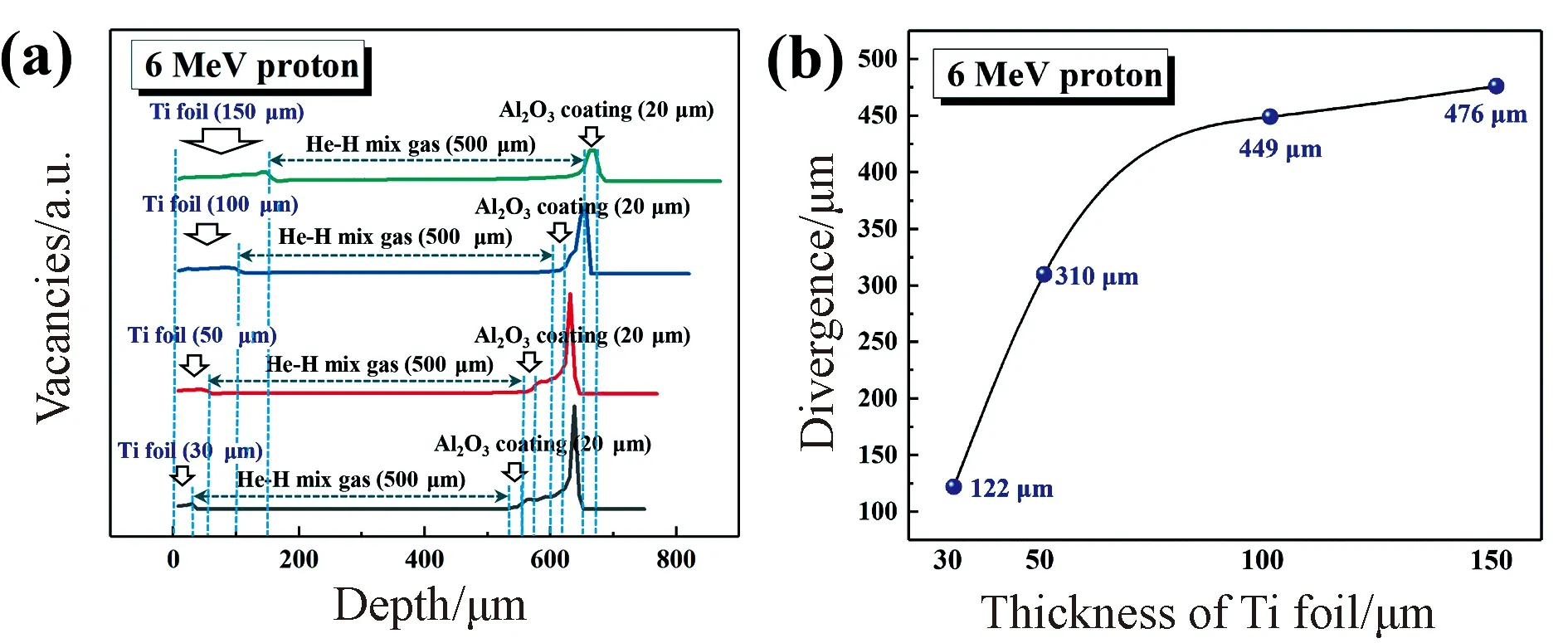
Fig.7 Simulation of (a) vacancies vary with irradiations depth and (b) divergence of proton beam for 6 MeV protons pass through the thickness of 30, 50, 100 and 150 μm Ti foils by SRIM
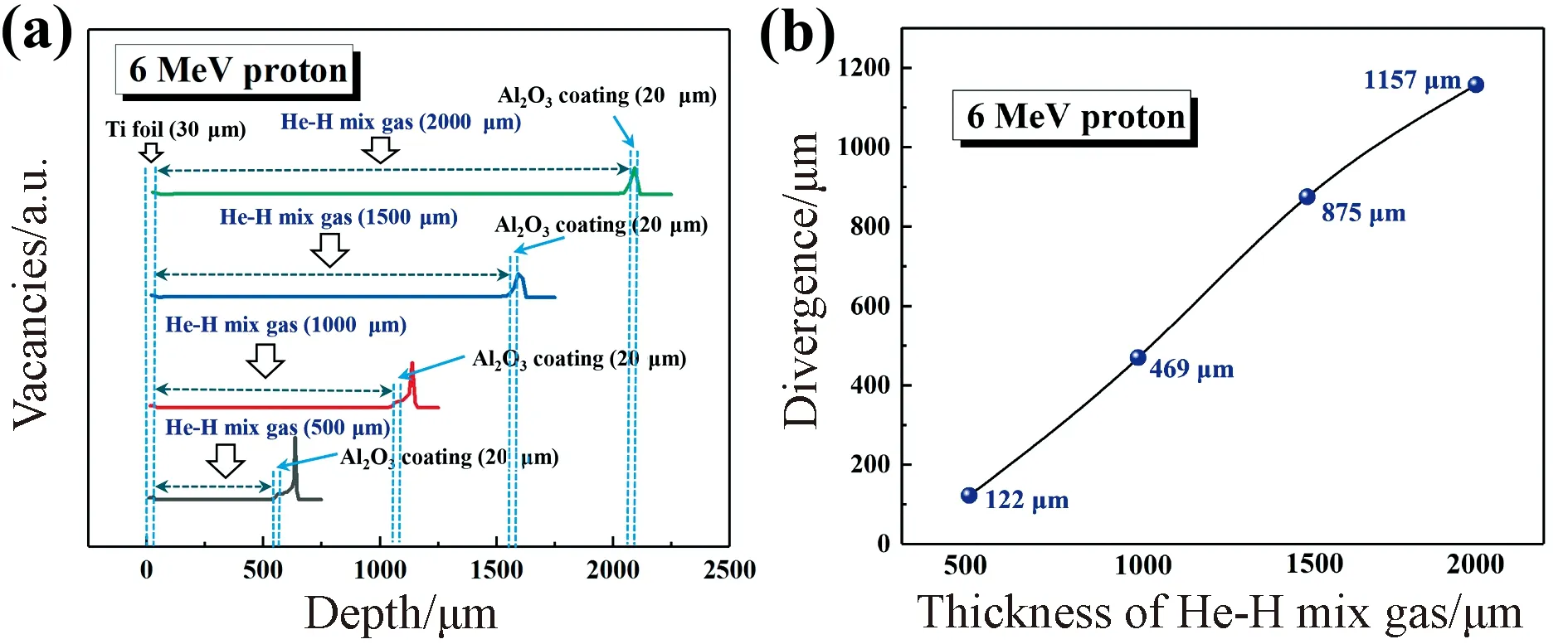
Fig. 8 Simulation of (a) vacancies vary with irradiations depth and (b) divergence of proton beam for 6 MeV protons pass through the thickness of 500, 1 000, 1 500 and 2 000 μm He-H mix gas calculated by SRIM software
The distance between separation foil and TPB coatings will have a slight change due to sample installation and gas pressure regulation, and it will change the thickness of He-H mix gas resulting in the difference of the experimental results. Fig. 8 shows simulation for 6 MeV protons pass through the thickness of the 500, 1 000, 1 500 and 2 000 μm He-H mix gas calculated by SRIM software, the thickness of Ti foil (30 μm), Al2O3coating (20 μm) and steel matrix (>100 μm) remained unchanged. Proton beam divergence increased with the increasing thickness of He-H mix gas from 500 μm to 2 000 μm, the proton beam exactly passed the Al2O3coating when the thickness of He-H mix gas up to 2 000 μm. It is indicated that the thickness of He-H mix gas cannot greater than 2 000 μm during the experimental process of sample installation and gas pressure regulating. Moreover, it is better to reduce the thickness of He-H mix gas as possible to guarantee the Al2O3coating suffering uniform damage by protons.
The thickness of the TPB coatings is a variable parameter in the process of experiment, which affect the results of experiment. Fig. 9 (take Al2O3coating as an example) shows simulation for 6 MeV protons pass through the thickness of the 20, 50, 100 and 200 μm Al2O3coatings calculated by SRIM software. The thickness of Ti foil (30 μm), He-H mix gas (500 μm) and steel matrix (>100 μm) remained unchanged. Proton beams penetrated 20, 50 and 100 μm Al2O3coatings successfully and passed exactly through the 200 μm Al2O3coating. Divergence of proton beam increasing with the increasing thickness of Al2O3coatings from 20 to 200 μm. The results indicated that the thickness of Al2O3coating should less than 200 μm to guarantee the experiments completed smoothly on this terminal. As for other TPB coatings, it should also keep the thickness at a suitable range in the process of experiment.
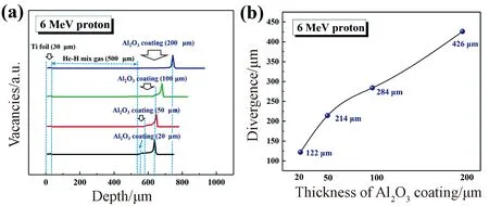
Fig.9 Simulation of (a) vacancies vary with irradiations depth and (b) divergence of proton beam for 6 MeV protons pass through the thickness of the 20, 50, 100 and 200 μm Al2O3 coatings calculated by SRIM software
3 Conclusions
The proton irradiation-high temperature-hydrogen permeation system developed at the 2×3 MV tandem accelerator in Sichuan University has been fully consolidated as a terminal for testing tritium permeation barrier coatings. The major components and design details of the terminal have been introduce, and the schematic illustrations and photos are combined to describe the terminal in more detail. The testing parameters such as the thickness of Ti foil, He-H mix gas, Al2O3coating and proton energy have been discussed, with a single variable controlled by using SRIM software. The simulation results provide a reference to optimize parameters of the terminal. In summary, the proton irradiation-high temperature-hydrogen permeation system provides an advanced test platform to evaluate the overall performance of TPB coatings.
猜你喜欢
中小学校长(2021年9期)2021-10-14 14:36:16
文史春秋(2019年10期)2019-12-21 01:40:50
质谱学报(2019年5期)2019-09-24 02:18:32
青年歌声(2019年2期)2019-02-21 01:17:20
中国核电(2018年4期)2018-12-28 06:28:18
先锋(2018年2期)2018-05-14 01:16:16
化工管理(2017年3期)2017-03-04 02:28:48
中国眼镜科技杂志(2016年9期)2016-12-01 06:37:33
汽车与安全(2016年5期)2016-12-01 05:21:56
生物骨科材料与临床研究(2016年6期)2016-03-06 08:20:12
