Negative compressibility property in hinging open-cell Kelvin structure*
Meng Ma(马梦), Xiao-Qin Zhou(周晓勤), Hao Liu(刘浩), and Hao-Cheng Wang(王浩成)
Key Laboratory of CNC Equipment Reliability,Ministry of Education,School of Mechanical and Aerospace Engineering,Jilin University,Changchun 130022,China
Keywords: negative compressibility,3D cellular model,open-cell Kelvin structure,analytical methods
1. Introduction
Over the past few decades, the metamaterials with negative property have attracted extensive researches due to their specialties and potentials for wide applications. The studies mainly focused on negative Poisson’s ratio,[1]negative thermal expansion,[2]negative stiffness,[3]negative permittivity,[4]and negative compressibility.[5–30]Although negative compressibility is the latest and least studied among these features, it offers a new insight into the nonconventional behavior that materials will expand in one or two directions under the hydrostatic pressure rather than shrink in all directions, exhibiting negative linear compressibility (NLC)or negative area compressibility (NAC).[5]These two properties do exist in stable systems[6–8]as the systems have positive volume compressibility, which indicates that negative volume compressibility(NVC)is non-existent in classical thermodynamics.[5]However,it is still possible for some foam structures to have the potential to be designed with NVC under pressure-induced phase transition[9]and metamaterials.[10,11]
The materials with negative compressibility are promising for potential applications due to the extraordinary mechanical property. Baughman et al.[5]predicted that NLC/NAC materials have potentials such as optical telecommunication line systems,sensitive pressure sensors and optical materials.Cairns et al.[12]presented that the NLC/NAC materials could be used as the optical components of pressure sensors, efficient biological structures and nanofluidic actuators.Recently,Grima et al.[13]provided a new view for designing the pressure sensors in nanonetworks with NLC due to the sudden changes in dimensions.
Up to now, there have been extensive materials proving to show negative compressibility. At a molecular level, the NLC behaviors have been demonstrated in plenty of materials, including nanonetworks,[13]methanol monohydrate,[14]Na(NH2BH3),[15]α-BiB3O6(BIBO),[16]oC24 carbon allotrope network,[17]MCF-34,[18]and LnFe(CN)6.[19]However,the NAC is found to be much harder than the NLC,which is currently discovered in a few materials such as potassium beryllium fluoroborate[20]and [Zn(L)2(OH)2]n·Guest.[21]At a micro level and macro level, a large number of twodimensional (2D) models or three-dimensional (3D) models have been proposed, the most classical model of which is wine-rack mechanism presented by Baughman.[5]This mechanism can be used to explain the negative compressibility behaviors of many materials such as nanonetworks,[13]methanol monohydrate,[14]α-BiB3O6,[16]and MCF-34.[18]From this point, the macro structures with negative compressibility can not only be used as blueprints for the design of system with negative compressibility, but also explain the deformation mechanism of materials with negative compressibility.[8]In addition to wine-rack mechanism, there are many other 2D structures proposed recently, such as hexagonal honeycomb mechanism,[22]bi-material strips,[23]truss-type systems,[24]hexagonal truss systems,[25]tetragonal beam structures,[26]rotating rigid units,[27–29]common materials,[30]and polygon with connecting rods.[31]
In addition to these 2D mechanisms,some 3D structures with negative compressibility have also been proposed. For example,Grima et al.[6]proposed a 3D cellular structure with negative compressibility,i.e.,the elongated hexagonal dodecahedron, which can have not only NLC and NAC, but also zero and negative Poisson’s ratio. Lim[32]proposed a ringrod structure which can have not only negative compressibility,but also negative thermal expansion and negative moisture expansion. Ghaedizadeh et al.[7]proposed two methods of designing and fabricating the composite structures with negative compressibility, which indicates that the composite materials are another important negative compressive material.Zhou et al.[8]constructed three different 3D analytical models based on the different layouts of the 2D wine-rack mechanism. And then Zhou et al.[33]and Ma et al.[34]used the 2D hexagonal truss mechanism and wine-rack mechanism to re-construct some new 3D cellular models, which prove that the arrangement of framework, the layout orientations of 2D mechanism and the number or length of rods can also change the extent of NLC and NAC.Similarly,the 3D structures can also be used to explain the negative compressibility behavior of many materials,of which the most important is the hinging octahedral structure. Yan et al.[35]proposed two rigid metalorganic frameworks MFM-133(M) (M =Zr, Hf) constructed in the form of an octahedron,which exhibits an unusual NLC behavior.
Although 3D models can realize more special properties and can be more easily used in practical applications than 2D mechanisms, so far there have existed only a few studies about extending the negative compressibility to 3D space and a few methods to be proposed to build 3D models with negative compressibility. The study about the 3D models with negative compressibility was relatively rare in previous research though it is significant, in this study, we propose a new 3D cellular structure based on the hinging open-cell Kelvin structure,[36–43]which is a typical form of cellular material and extensively used in diverse industrial, biomedical and chemical applications. Specifically, the expressions of Young’s moduli and the Poisson’s ratios as well as compressibility are given and discussed. It is shown that this model has adjustable compressibility and does exhibit NLC and NAC.Further study shows that the images of compressibility are symmetrical about the certain lines, which indicates that the mechanical properties of the model in the three axial directions are interchangeable and the model itself has a certain geometric symmetry. Moreover, it is found that the Kelvin model has a stronger negative compressibility property than the anisotropic form and the dodecahedron model in all three directions. From these, a new and potential method to improve negative compressibility property can be derived by selecting the system type with lower symmetry and increasing the number of geometric parameters. All of these are covered in detail in the following sections. Note that there is a Supplementary information in this work, mainly including the detailed deformed images under uniaxial compression and hydrostatic compression, the derivation of the expressions of Young’s moduli and Poisson’s ratios,the validation of Young’s moduli, and the 2D simplified contour plots of the area compressibility.
2. Hinging mechanism of Kelvin model
The model proposed in this study is mainly based on the hinging Kelvin structure,which is a typical form of open-cell porous materials shown in Figs.1(a)and1(b). And this system possesses a space-filling structure with two types of unit cell arrays, i.e., the tetrakaidecahedron cell[36](Fig.1(c))and the characteristic unit cell[37](Fig. 1(d)). The former possesses 14 faces (i.e., 6 tetragons and 8 hexagons), 24 vertices, and 36 edges, with all 6 tetragons distributed in the centers of 6 surfaces separately. The latter is the characteristic form of the Kelvin model that plays a more significant role in the theoretical and simulation analysis.
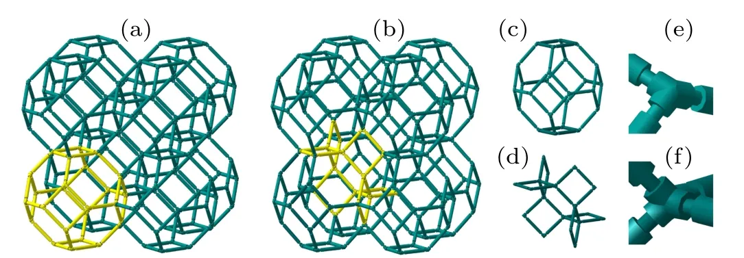
Fig. 1. [(a), (b)] Clusters of Kelvin model with two unit cell arrays, (c)tetrakaidecahedron cell,(d)characteristic unit cell,[(e),(f)]details of flexure hinge at vertex for two unit cells.
Unlike the isotropic form in which all rods and angles must be the same, the model studied here is a more generalized form of open-cell Kelvin structure and the generality in this model could be gained by using different angles and lengths of the rods. The lengths of rods parallel to the OX2–OX3plane, the OX1–OX3plane, and the OX1–OX2plane are denoted as l1,l2,and l3,and the corresponding angles are denoted as θ1,θ2,and θ3,which are illustrated in Fig.2.
Before making concrete analysis, it is necessary to elaborate several assumptions of the model. Firstly, in order to better produce a negative compressibility deformation,an idealized hinging model should be set up in this model,that is,all rods in the model are completely rigid and can be deformed only when the angle between the rods is changed. However,in the actual system, the hinging deformation is always accompanied with bending deformation and stretching deformation, which will lead the negative compressibility to deviate from the value predicted from the idealized model. Therefore,as we previously set,[33]flexible hinges are also used to connect the joints between rods in this work, which can enhance the hinging deformation and weaken the other deformations,thus making the actual model closer to an idealized model.The unit-cell with flexible hinges can be clearly illustrated in Figs.1(c)and 1(d)and the details of the flexure hinges can be observed in Figs.1(e)and 1(f).
In order to more vividly explain the mechanism to produce negative deformation, commercial finite element software ANASY/Workbench version 15.0 is adopted to gain a further insight into the responses of the three configurations of the model, separately, under the uniaxial and uniform compression loading. The FE models of the three configurations for compression is depicted in Fig. 3 and the dimensions of the configurations are chosen to be(45°,45°,45°),(60°,60°,45°),and(30°,30°,45°)with l=10 mm. In order to produce more obvious deformation,the resin is adopted to the models with ρ =1300 kg/m3, E =2.52 GPa, and υ =0.41, and the structural steel is chosen for the platens with ρ=7850 kg/m3,E=200 GPa,and υ=0.3. Mesh convergence analysis shows that the element size of 0.50 mm is enough to generate accurate results. No separation contacts are defined between the platens or between the models. Finally,a pressure of 1000 Pa is applied to the platen to test whether uniaxial compression or uniform compression happens.
The simulation results are also shown in Fig. 3, and the more detailed deformed simulation images in different directions and the stress distribution images can be seen in the Supplementary information. It can be seen from the images(Figs.3(b),3(f),and 3(j))that the three configurations all contract when uniaxial compression is implemented in the Z direction(i.e.OX3)and the amount of the compression increases gradually. Due to the boundary effect,the deformation of the central region will be clearly observed to explain the mechanism of the model. It can be found that the rods in the horizontal plane(i.e.l3)still keep basically horizontal and none of them deforms under the uniaxial compression in the Z direction,and the rods in the vertical planes(i.e.l1and l2)mainly deform through the angle. Therefore, the deformation process of the three configurations with flexure hinges confirms to the setting of the idealized hinging model. When the configurations are subjected to uniform compression, it can be found that the configuration with(60°,60°,45°)can produce a negative compressibility deformation in the OX3direction and the configuration with(30°,30°,45°)will produce a negative compressibility deformation in the OX1and OX2directions,separately,which proves that the configuration with(60°,60°,45°)has NLC in the OX3direction and the configuration with(30°, 30°, 45°) has NLC in the OX1and OX2directions. Finally,it should be noted that the simulation results can only act as the qualitative observation and explanation of the negative compressibility deformation of the model and the value of deformation directly obtained from the simulation results cannot be used to obtain the specific value of the mechanical property of the model due to the boundary effect,the selected material of the model and the design of the flexure hinge. The reference points for quantitative analysis of the mechanical properties need to select those that are in the intermediate region and the relevant qualitative simulation and experimental verification will be carried out in our follow-up work.
It can be found from the above discussion that when the flexure hinges choose suitable material or geometry to make its stiffness constant much less than that of the rods, the rods in this model will only produce hinging deformation rather than bending deformation that is more frequently happens to the porous materials. And the porous structures with the flexure hinge can be manufactured in a variety of processing methods, such as 3D printing,[41]selective laser sintering,[42]and projection microstereolithography.[43]The work on designing the flexure hinge mainly includes two parts, i.e., the geometric design and the material selection. The geometric design is mainly to select and optimize the shape, cross-sectional area and length of the flexure hinges to enhance the hinging deformation and weaken the other deformations, which can be completed together with the model by 3D printing. The material selection is implemented mainly through choosing the composite material to make the difference between the rods and the hinges to enhance the hinging deformation and weaken the other deformations,which will be manufactured separately from the rods and finally assembled together by splicing or welding. The design of the flexure hinge and the effect of the nonuniformity of the unit cell or the hinges are an important task, which will be carried out in our follow-up work. And when the flexure hinges are chosen suitable,the overall deformation of the model will mainly depend on the deformation of the hinges, and the influence of many features of the rod itself(such as material,shape,length,area)on the overall deformation is insignificant. Therefore, in the stage of elastic deformation, the stiffness of the mechanism is related to the stiffness of the hinge that resists the change of angle between rods, and the relationship between the stiffness constant and load can be expressed as

where M is the moment applied to the rod, δθ is the angular displacement due to the moment,and khis the rotational stiffness constant of the hinge. Although the flexible hinge can meet the setting of the idealized hinging model,neither of the bending and stretching deformation can be eliminated in the actual system. And the bending and tensile deformation directly depend on the length and shape of the rod,which limits the rods of the model to being not too long or too thin.
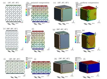
Fig.3. FE models and simulation results under uniaxial and uniform compressions: [(a)–(d)]configuration with(45°,45°,45°);[(e)–(h)]configuration with(60°,60°,45°);[(i)–(l)]configuration with(30°,30°,45°).
In addition,in order to ensure negative compressibility to be generated normally, the uniform pressure subjected to the model can only act on the surface,but cannot be immersed into the model.Therefore,when the model is tested in or applied to an actual system,it is necessary to wrap a layer of sealed plastic bag[7]with a certain rigidity on its outer surface. And in this case,the model can not only be placed in the hydrostatic pressure, but also be exerted on by a uniform pressure from an air compression. Finally, it should be emphasized that all negative compressibility property discussed below holds true only for the case of small deformation.
3. Mechanical properties of Kelvin model
In this part,the mechanical properties of the Kelvin model is deduced and obtained for the discussion of negative compressibility property. As for the Kelvin multi-cells model shown in Figs.1 and 2,it could be obtained by aligning the unit cell vectors along the OX1, OX2, and OX3directions. Therefore,the projections of the unit cell in the three directions can be given by

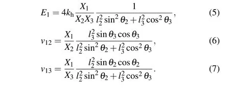
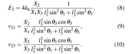
Considering that the model should be physically realized, the normal conditions, that is, l1>0, l2>0, l3>0,90 >θ1>0, 90 >θ2>0, and 90 >θ3>0 need to be satisfied. Before calculating the expressions of compressibility,we should first figure out the expressions of Young’s moduli and Poisson’s ratios in relevant directions. And referring to the analysis discussed elsewhere,[6,8,33]the expressions of Young’s moduli along the three axes and Poisson’s ratios in the three projection planes can be obtained below,and the detailed derivation and verification can be found in the Supplementary information.
Loading in the OX1direction:
Loading in the OX2direction:
Loading in the OX3direction:
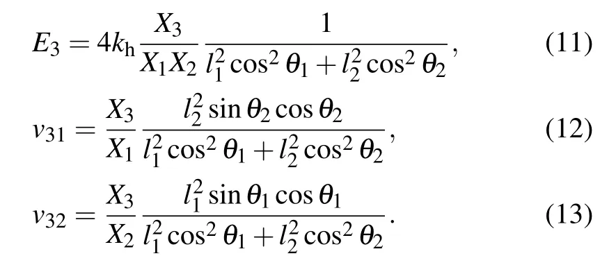
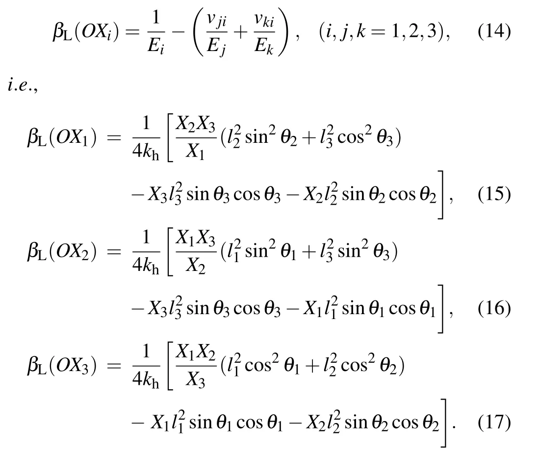
Based on the expressions of Young’s moduli and Poisson’s ratios,the linear compressibility along the OXidirection can be determined by substituting Eqs. (5)–(13) into the following equation:
The area compressibility in the OXi–OXjplane and the volume compressibility can be obtained from the following formulas. And the specific expressions are omitted here for the sake of simplification.

For reducing the complexity of discussion, we set the length parameters to be the same, i.e., l1=l2=l3=l. The equations for the linear compressibility can be simplified, in which way the simplified equations for the area and volume compressibility can be obtained. In addition, for the convenience of expression in the following discussion, the linear compressibility in the OX1, OX2, and OX3directions can be also directly expressed as β1, β2, and β3. Similarly, the area compressibility in the OX1–OX2, OX1–OX3, and OX2–OX3planes can be also directly expressed as β12, β13, and β23:

4. Discussion
Equations(18)–(22)show that if the value of l is assumed to be constant,the signs and magnitudes of the line,area and volume compressibility are dependent mainly on the angle parameters (i.e., the values of θ1, θ2, and θ3). And it can be proved from Figs. 4 and 5 that the model does exhibit NLC and NAC.In the following section,we will mainly discuss its angle parameter features and the comparisons in its two special cases(i.e.,the anisotropic form and the dodecahedron model)in terms of negative compressibility.
The 3D contours of the linear, area, and volume compressibilities across various angle parameters are plotted in Fig.4,which confirms that the model exhibits NLC and NAC.And these images can also clearly show the angle ranges to obtain negative compressibility,where the green surfaces correspond to zero compressibility and the yellow, orange, and red surfaces correspond to negative compressibility. What can also be observed from Fig.4 is the variation trend of compressibility, which corresponds to the changing process of surface color from red to green and then to blue. Note also that the diagrams shown in Figs.3(a)–3(c),and Figs.3(d)–3(f)have the same shapes with different orientations, which indicates that the geometry of model is so symmetric that the three angle parameters θ1, θ2, and θ3are equivalent in affecting the values of compressibility. The same regularity is also reflected in the expressions of Young’s moduli, The Poisson’s ratios and compressibilities (i.e., Eqs. (5)–(13) and Eqs.(15)–(17)),which are all highly similar and unified. Therefore, it can be concluded that the angle parameters θ1, θ2, and θ3influence the mechanical properties of the model equivalently. Moreover,from a mathematical point of view,the minimum values of the three linear compressibilities,when kh=0.25 kJ·rad−1and l1=l2=l3=l =10 mm, are all about −1.319 GPa−1and those of the three area compressibilities are all about−1.871 GPa−1, which also verifies the previous discussion about the similarity of compressibility. It is also of interest that the minimum values of the three linear compressibilities can occur at two points, which can infer that the linear compressibility of the model itself can also have some symmetrical relationships. In addition, the minimum of the volume compressibility is 0 when θ1=θ2=θ3=45°, i.e., NVC is non-existent in this model.
In order to analyze more specific and accurate information about negative compressibility, we can simplify the 3D images by assigning specific values to angle parameter in each given direction, and then drawing the corresponding 2D images. Specifically,for this model,we set specific values of θ3:we select 30°,45°,and 60°for the linear compressibility and select 25°,45°,and 65°for the area compressibility.
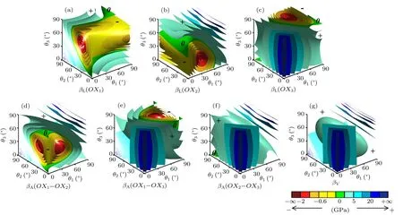
Fig.4. The 3D contour for the linear[(a), (b), (c)], area [(d), (e), (f)], and volume (g) compressibility for this model across various angles of θ1, θ2,and θ3 with kh =0.25 kJ·rad−1 and l1 =l2 =l3 =l=10 mm, with 0, +, and −in images representing zero, positive, and negative compressibilities respectively.
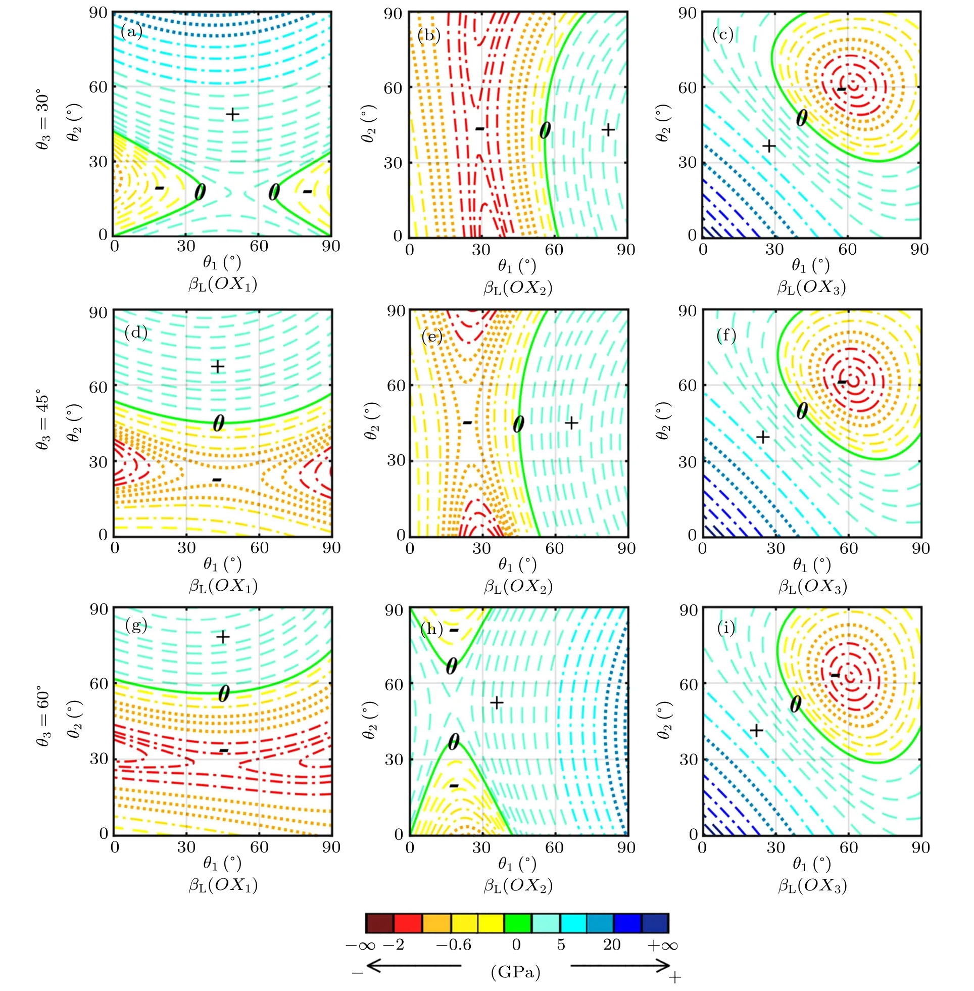
Fig.5. The 2D contours for linear compressibility across various angles of θ1 and θ2 with kh=0.25 kJ·rad−1 and l1=l2=l3=l=10 mm,with panels(a), (b), and(c)corresponding to θ3 =30°, panels(d), (e), and(f)corresponding to θ3 =45°, panels(g), (h), and(i)corresponding to θ3 =60°, and symbols 0,+,−in images referring to zero,positive,and negative compressibilities respectively.
The 2D contours of the linear compressibility after angle simplification are shown in Fig. 5, in which the color definitions are chosen to be the same as those in the 3D images.And we can analyze the influence of each angle parameter on the linear compressibility by comparing these three groups of images. For example, we first observe images 5(c), 5(f),and 5(i),which correspond to the images of β3with different values of θ3.When looking at each image separately,it can be found that whether in horizontal direction or in vertical direction,the value of β3changes dramatically in the whole range of angles, which shows that angle parameters θ1and θ2have a great effect on β3. When observing the three images together, the differences among are tiny and negligible, which indicates that the angle parameter θ3has a little effect on β3.Moreover, comparing these three images with the 3D image shown in Fig. 4(c), it is easier to find that the image of β3is approximately distributed along the OX3direction. Therefore,it can be summarized that for β3, the influence of parameter θ3is obviously inferior to that of θ1and θ2, indicating that the former only slightly affects the value of compressibility,while the latter two affect in the whole range. The same rules can be also obtained by comparing Figs. 5(a), 5(d), 5(g) and Figs.5(b),5(e),5(h),respectively.Although the observation is not so obvious as the previous one,it can be found from these two groups of images that parameters θ1and θ2both have a strong influence on the values of β1and β2in the scope where the minimum values of β1and β2are obtained, respectively.Therefore, the conclusion above is applicable to that for βi,the influence of θjand θkare obviously stronger than that of θi(i,j,k=1,2,3), in which the former have an effect in the whole range, while the latter only drastically affect the value of βiin the scope where the minimum value of βiis obtained.

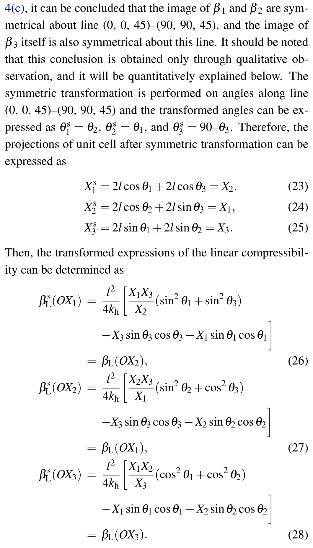
It can be found that the transformed expressions of the three linear compressibilities, i.e., βs1, βs2, βs3, are exactly the same as the expressions of β2,β1,and β3accordingly. Therefore, the above hypothesis about image symmetry is quantitatively verified. In order to explain this conclusion more vividly,we can rotate the model 90°along the OX3axis. It can be found that after these two operations, the models have exactly the same structure form, which suggests that in a sense the symmetric operation is equivalent to the rotation operation about the vertical direction. All of these are illustrated in Fig. 6. And under this rotation operation, all parameters in the OX1and OX2directions are exchanged, including angles, projections, Young’s moduli, Poisson’s ratios, and compressibilities,which proves that the images of these characteristics in the two directions are symmetrically distributed along this symmetry line. Moreover, all the mechanical properties of the model in the two horizontal directions are interchangeable after the rotation operation,which also indicates that the model itself has a geometric symmetry about the symmetry line. For the OX3direction, due to the difference in the definition between angle parameters,the angle before the rotation operation and the angle after the rotation operation are mutually complementary angles,but the other characteristics are exactly identical, which indicates that the image of β3itself is also symmetrical about this symmetry line. Similarly,when θ1and θ2are set to be specific values, the symmetry lines of the other linear compressibilities can also be found and the conclusions are shown in Table 1.

Fig.6. Diagrammatic illustration of Kelvin model after symmetric operation and rotation operation.

Table 1. Symmetry lines of linear compressibility and area compressibility in various cases.
In the same way,we can also study the area compressibility and the 2D contours of the area compressibility in the three planes after angle simplification,which are shown in Fig.S6 of Supplementary information. Comparing them with the counterparts of 3D images shown in Figs.4(d)–4(f),the symmetry lines of the area compressibility can also be found and the specific conclusions are shown in Table 1. Note that the analysis about the image symmetry is not only for compressibility,but also for many other mechanical properties,including Young’s moduli,Poisson’s ratios,etc.,which proves that these mechanical properties are also interchangeable in the three directions and the model itself has geometric symmetry about the symmetry line.And it is obviously more important for the geometric symmetry of the model itself that the model can change the geometric parameters of the model through symmetric transformation to obtain the completely symmetric and identical mechanical properties. Finally, it should be highlighted that the image symmetry and geometric symmetry discussed here are very important,not only because the image symmetry and geometric symmetry themselves in the three directions are rare, after all, the models with negative compressibility studied previously[6,8,33,34]have image symmetry and geometric symmetry only in the two horizontal directions,but also due to the fact that this model can possess some parameter-controlled applications, in which many performances in the three directions are completely interchangeable by selecting appropriate geometric parameters.
Having analyzed the angle parameter features, we can now discuss some special cases of the Kelvin model. It should be noted that the Kelvin model is normally studied in two forms,i.e.,the isotropic form[36]and the anisotropic form[38]as shown in Fig.7. And in the isotropic form, all three angle parameters are 45°,and for the anisotropic form the angle parameters can be described as θ1=θ2=θ,and θ3=45°. Under this anisotropic condition, the corresponding expressions of the linear compressibility can be expressed as

It can be seen that the expression of β1and β2are exactly the same. And referring to these formulas,the NLC will be exhibited when the following conditions are satisfied:for negative β1=β2,

for negative β3,

It indicates that in this anisotropic case,the model can exhibit NLC simultaneously in the OX1and OX2directions but NLC in the OX3direction can never arise in this range. Then taking derivation of Eqs. (29) and (30), we can know that the maximum value of NLC in the OX1and OX2directions will occur at θ ≈24.2°and the maximum NLC in the OX3direction appears at θ ≈61.8°. And the minimum values in three directions when kh=0.25 kJ·rad−1and l =10 mm are about −0.935,−0.935,and −1.260 GPa−1respectively. The three minimum values are all larger than those in the general form. Moreover,the isotropic form of this model also needs to be introduced,i.e.,θ1=θ2=θ3=45°. It is obvious that when the model is under this condition, the values of the linear compressibility are all 0, which implies that the NLC is non-existent in this form.
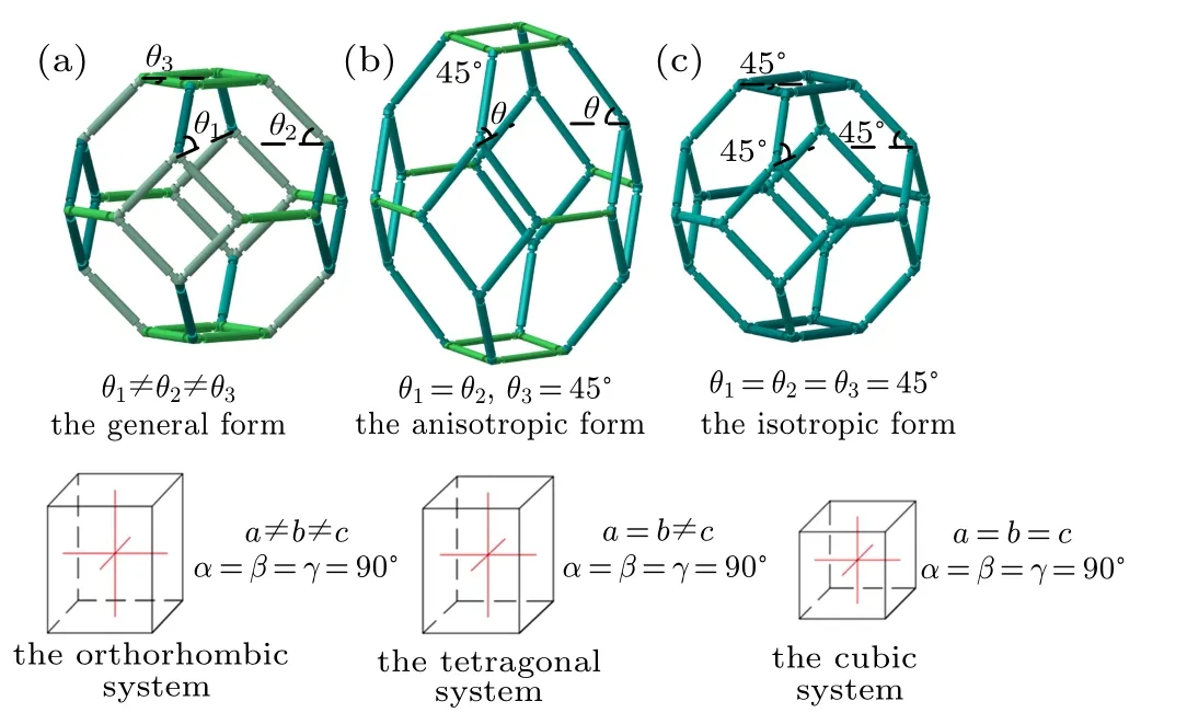
Fig. 7. (a) General form of Kelvin cell, (b) anisotropic form, and (c) orthotropic form, correspond to orthorhombic, tetragonal, and cubic systems respectively.
Through the comparison among these three forms,it can be found that for the Kelvin model,the greater the anisotropy of the structure, the larger the maximum negative compressibility is and the NLC will disappear when the structure is isotropic. And referring to the concept of crystal system, the general form has three perpendicular but unequal axes,which can be seen as an orthorhombic model. And the anisotropic and isotropic form belong to the tetragonal model and the cubic model, respectively. In addition, Cairns and Goodwin[44]pointed out that the directional dependence of negative compressibility property can be relative complex when the crystal symmetry is low due to the fact that it will lead to shear component in the compressibility tensor. Ma et al.[45]proposed a monoclinic octahedron model based on the tetragonal octahedron model by changing the system type, which proves that the negative compressibility property can be improved in the horizontal direction. Therefore, it may be inferred that the greater the symmetry of the system, the weaker the negative compressibility property is. It is very important because it provides a new and potential method to improve negative compressibility property by selecting the system type with lower symmetry,such as the monoclinic system,the trigonal system,the hexagonal system, and even the triclinic system. In the meanwhile,it can also be regarded as a reference to designing new models with negative compressibility.
In addition to the anisotropic form and isotropic form,the dodecahedron model[8]can be seen as another special case of the Kelvin model, which has been discussed in detail in our previous work as shown in Fig. 8. It can be seen from this figure that the dodecahedron model can be regarded as a special case of Kelvin model when the length parameter l3is zero,and the angle parameter θ3will also disappear. According to this, the expressions of the linear compressibility for the dodecahedron model can be obtained by deleting l3and θ3in the relevant expressions of the Kelvin model as
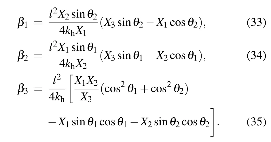
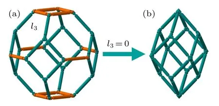
Fig.8. (a)Kelvin model and(b)dodecahedron model.
It shows that the expressions are the same as those in our previous work.[8]And by taking derivation of these three equations, the maximum value of NLC in the OX1, OX2, and OX3directions when kh=0.25 kJ·rad−1and l=10 mm are about−0.6006, −0.6006, and −0.8301 GPa−1, respectively. It can be found that the three minimums are all larger than those of the Kelvin model, which means that the negative compressibility properties of the dodecahedron model in all three directions are weaker than those of the Kelvin model. Moreover,it should be also noted that the Kelvin model can be regarded as a structure with three sets of geometric parameters (i.e.,l1/θ1, l2/θ2, and l3/θ3), while the dodecahedron model only has two sets of geometric parameters (i.e., l1/θ1and l2/θ2).It is this extra set of parameters that increases the anisotropy of the model, which leads to stronger negative compressibility property of the Kelvin model. In addition,Grima et al.[22]pointed out that the value of h/l in hexagonal honeycombs can favor the negative compressibility property in the direction of h. Similarly,Zhou et al.[33]proposed several 3D models constructed by hinging hexagonal truss mechanism, which also proves that the value of h/l in hexagonal honeycombs can improve the negative compressibility property in the direction of h. Ma et al.[34]proposed three models constructed by hinging wine-rack and hexagonal truss mechanism, which show that increasing the number or length of the rods in the vertical direction can improve the negative compressibility property in this direction. Therefore,it can be inferred that increasing the number of rods with deformation can increase negative compressibility property of the model,and more importantly,it can improve the negative compressibility property in all three directions. Note that this finding not only proves that the Kelvin model has stronger negative compressibility property than the dodecahedron model, but also proposes a new and potential method to improve the negative compressibility, which will increase the anisotropy of the model by adding the geometric parameters. Finally,there is an interesting point that the maximum values of NLC in the anisotropic form are all larger than in the dodecahedron model. Although the two models cannot be directly compared with each other and the anisotropic form has a set of geometric parameters (l/θ), it should be noted that the anisotropic form should be regarded as having three sets of geometric parameters(l/θ,l/θ,l/45°). And the number of the geometric parameters in set should be the number of geometric parameters in each direction rather than the number of independent variables, which is mainly because all the geometric parameters in the three direction form the model and they can be reflected in the projection length of each direction in the expression of compressibility. In addition,it can be found that the maximum values of NLC in the general form and anisotropic form are all multiples of that in the dodecahedron model,which is mainly due to the fact that the geometric parameters of l/45°multiply increase the area of the model bearing uniform pressure in each plane and produce more negative compressibility deformation.
Before concluding, it should be noted that the open-cell Kelvin structure, as a typical form of cellular material, are widely used as ultralight structural component,[39]bone substituting biomaterial[40]and catalytic substrate.[41]However,the researches in this field mainly focus on its anisotropic form[36]and uniaxial loading.[38]And the present work provides a new idea for studying the open-cell Kelvin structure,in which more general and hinging form is considered when the structure is loaded in the three axis directions,which may make the material show some extraordinary characteristics different from the traditional material. Moreover,the conclusion about the symmetry of mechanical properties in three directions also provides a reference for studying other properties,such as chemical, acoustic, and thermal, which may be also tailored or even interchanged in three directions by selecting geometric parameters. Furthermore,there are many manufacturing methods that allow the material behaviors to be manipulated consciously by changing the morphology of structure,such as 3D printing,[41]selective laser sintering,[42]and projection microstereolithography,[43]which can provide a guarantee for the follow-up study of this work. In conclusion, although the study is carried out only through theoretical analysis and the model has some limitations,it should be also noted that the model and conclusions studied in this work are very important,not only due to the fact that the Kelvin model does exhibit NLC and NAC,but also because it provides a method to improve negative compressibility property by selecting the system type with lower symmetry and increasing the number of geometric parameters. In addition, it can explain the mechanical behavior with this model,and if the systems are synthesized in this way,they can indeed have NLC and NAC.And the extension in image symmetry and the improvement of negative compressibility, may further extend the applicability of explaining and predicting the mechanical behaviors or some other special behaviors in practical applications.
5. Conclusions
In this paper,a new 3D cellular model based on the hinging open-cell Kelvin structure is proposed and the expressions of its mechanical properties are given and discussed, such as Young’s modulus,Poisson’s ratio,and compressibility. In addition, we analyze angle parameter features of the model in detail and compare it with its two special cases in terms of negative compressibility. The specific conclusions are as follows.
(i) The Kelvin model does have NLC and NAC and can be tailored for specific applications by choosing the appropriate parameters. Moreover, the model has image symmetry in three directions, which indicates that the mechanical properties in three directions are interchangeable and their images are symmetrical. The specific symmetrical lines are also given.
(ii)The anisotropic form and the dodecahedron model can be regarded as two special cases of the Kelvin model. When comparing the Kelvin model with them, it can be found that the Kelvin model has strong negative compressibility property in all three directions. Therefore, a new method to improve negative compressibility property can be inferred by selecting the system type with lower symmetry and increasing the number of geometric parameters.
Finally,in view of the importance of this work,we expect the findings here to be able to serve as a blueprint for designing and developing the more superior applications in the future.
- Chinese Physics B的其它文章
- Corrosion behavior of high-level waste container materials Ti and Ti–Pd alloy under long-term gamma irradiation in Beishan groundwater*
- Degradation of β-Ga2O3 Schottky barrier diode under swift heavy ion irradiation*
- Influence of temperature and alloying elements on the threshold displacement energies in concentrated Ni–Fe–Cr alloys*
- Cathodic shift of onset potential on TiO2 nanorod arrays with significantly enhanced visible light photoactivity via nitrogen/cobalt co-implantation*
- Review on ionization and quenching mechanisms of Trichel pulse*
- Thermally induced band hybridization in bilayer-bilayer MoS2/WS2 heterostructure∗

