Nonlinearity-Compensation-Free Optical Frequency Domain Reflectometry Based on Electrically-Controlled Optical Frequency Sweep
Abstract—A nonlinearity-compensation-free optical frequency domain reflectometry (OFDR) scheme is proposed and experimentally demonstrated based on the electrically-controlled optical frequency sweep.In the proposed scheme,the linear frequency sweep light is generated by propagating an ultra-narrow-linewidth continuous-wave(CW) light through an electro-optic frequency shifter which consists of a dual-parallel Mach-Zehnder modulator(DPMZM) and an electronic 90° hybrid,where the electro-optic frequency shifter is driven by a linear frequency modulated signal generated by a direct digital synthesizer (DDS).Experimental results show that the spatial resolution and signal-to-noise ratio (SNR) of the proposed OFDR scheme without the nonlinear phase compensation are comparable to those of OFDR employing a commercial tunable laser source (TLS),an auxiliary interferometer,and a software-based nonlinear phase compensation method.The proposed OFDR scheme is helpful to reduce the complexity of the optical structure and eliminate the difficulty of developing the nonlinear phase compensation algorithm.
1.Introduction
The optical frequency domain reflectometry (OFDR) becomes a powerful tool to realize measurement and sensing since its first demonstration by Eickoff and Ulrich in 1981[1].In the past decades,a great effort has been devoted to the mechanism and the potential applications of OFDR[2],[3].The applications of OFDR mainly include two aspects.On the one hand,it can be utilized to monitor an optical fiber link,where the fiber loss and the position of the breakpoint are measured[4]-[7].On the other hand,it can be employed to realize distributed sensing of the temperature,strain,vibration,magnetic field,and so on[8]-[11].
A tunable laser source (TLS) is an essential device in OFDR.In order to achieve high spatial resolution and a large measurement range,TLS with its frequency linearly sweeping is required.However,in actual TLS,nonlinear frequency sweeping is inevitable,which should be well compensated to enhance the measurement range and spatial resolution[2],[3].The existing nonlinearity compensation methods can be categorized into two groups.The first one is based on the hardware compensation[12],[13],which uses the signal from an auxiliary interferometer(Michelson structure) as the sampling clock to realize equal optic-frequency-interval sampling of the signal from the main interferometer.The defect of this method is that the maximum monitoring distance is limited by the optical path difference between the two arms of the auxiliary interferometer.The sampling frequency of the system,according to Nyquist's theorem,should be at least twice that of the main interference signal.Therefore,the length of the fiber under test (FUT) in this method can only be half of the optical path difference between two arms in the auxiliary interferometer.When the measured fiber length is extended,the multiple increases of the delay fiber will increase the redundancy of the system.Hence,the measured fiber length of the demonstrated systems based on this method is generally between tens of meters and hundreds of meters.The second method is based on the software compensation,which uses the nonlinear phase information in the auxiliary interferometer to compensate for the beat signal from the main interferometer via the nonlinear phase compensation algorithm.One of the software compensation methods is resampling,including linear interpolation,spline interpolation[14]-[16],and non-uniform Fourier transform[16],[17].The prominent advantage of the resampling method is that the measured distance is no longer limited by the optical path difference between the two arms in the auxiliary interferometer.However,this method cannot completely eliminate the nonlinear tuning effect of the light source in theory,where its effect on long distance measurement is nonnegligible.The other method is the phase noise compensation,including the concatenation-generated phase[18],phase mixing[19],and deskew filter[20],[21].Although the phase noise compensation greatly improves the measured distance and spatial resolution,these algorithms are relatively complex,and some of them are time-consuming.In addition,in the above-mentioned nonlinearity compensation methods,an auxiliary interferometer is indispensable,which increases the system complexity.
In this paper,an OFDR scheme without the need of compensating nonlinearity is proposed and experimentally demonstrated.This scheme only involves a single interferometer,in which TLS is realized based on the electricallycontrolled optical frequency sweep by using an ultra-narrow-linewidth fiber laser source,an electro-optic frequency shifter,and a direct digital synthesizer (DDS).In the experiment,the linear frequency sweep light with the linearity of 1.57% is generated and used to achieve OFDR.Through comparing the experimental results of the proposed OFDR scheme with that using commercial TLS and the auxiliary interferometer with the nonlinear phase compensation,the spatial resolution and signal-to-noise (SNR) are comparable.
2.Operational Principle
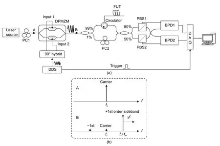
Fig.1 shows the schematic diagram of proposed OFDR.The continuous-wave (CW) light from an ultra-narrowlinewidth fiber laser source enters an electro-optic frequency shifter which consists of a dual-parallel Mach-Zehnder modulator (DPMZM) and an electronic 90° hybrid.DPMZM works in the mode of carrier-suppressed single sideband (CS-SSB) modulation realized by biasing the parent Mach-Zehnder modulator (p-MZM) and the two sub-MZMs at the quadrature point and the minimum transmission point,respectively.Through applying a linear frequency modulated signal generated by DDS to the electro-optic frequency shifter,an electrically-controlled linear frequency sweep optical signal is generated from DPMZM,as shown in Fig.1 (b).The linear frequency sweep optical signal is divided into two branches by a 99:1 optical coupler (OC),where 99% of the power enters FUT via an optical circulator,and the other 1% of the power propagates through a reference fiber.The backscattered and reflected light from FUT is recombined with the light from the reference fiber via 2 × 2 OC,where the optical signals from the two output ports are detected by two balanced photodetectors (BPDs) after polarization splitting by two polarization beam splitters (PBSs).The beat signals from the two BPDs are captured by the digital data acquisition(DAQ) which is triggered by DDS.The distributed information in FUT is obtained through transforming the acquired time-domain signal to the frequency domain via fast Fourier transform.

Fig.1.Proposed OFDR based on the electrically-controlled optical frequency sweep:(a) schematic diagram and(b) spectrum of the carrier and modulated lightwaves.
3.Experimental Results and Discussion
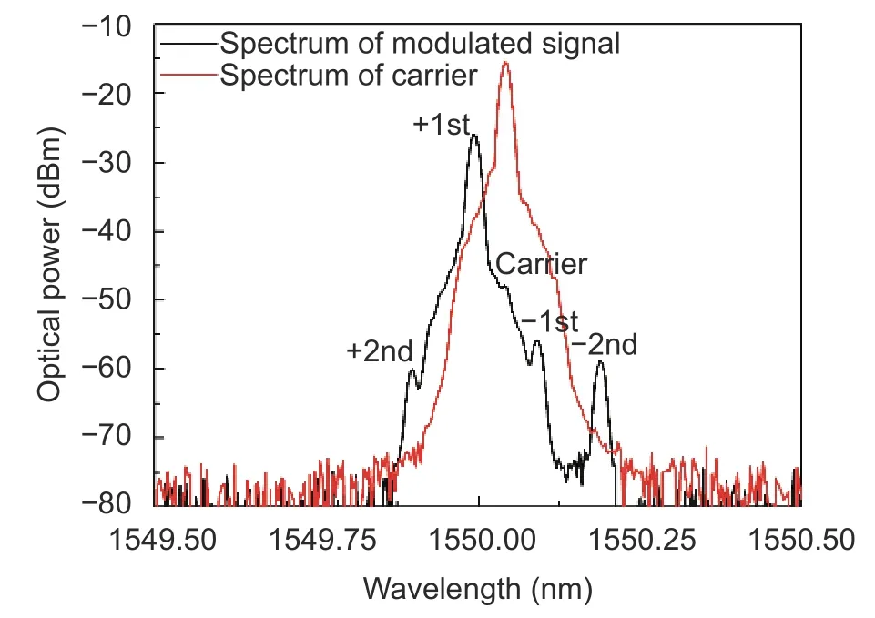
A proof-of-concept experiment was carried out to verify the performance of the proposed OFDR scheme.In the experiment,the CW light at 1550.04 nm with a linewidth smaller than 0.1 kHz was outputted from an ultra-narrowlinewidth fiber laser source with the maximum output power of 40 mW (Koheras Basik E15,NKT Photonics).Then,the CW light propagated through an electro-optic frequency shifter which consists of 40-Gbps DPMZM (COVEGA Mach-40086) and an electronic 90° hybrid (ABACUS MICROWAVE 9-010180,1 GHz to 18 GHz) to generate the linear frequency sweep optical signal,where the electro-optic frequency shifter was driven by a linear frequency modulated signal in a frequency range of 4 GHz to 8 GHz with the duration of 100 μs (i.e.,with a chirp rate of 40000 GHz/s) from home-made DDS.Fig.2 presents the frequency-time diagram of the linear frequency modulated signal generated by DDS.The frequency sweep linearity is 1.57%.The optical spectra before and after CS-SSB modulation for a single-tone input microwave signal with a frequency of 6 GHz are exhibited in Fig.3.The suppression ratios of the carrier and the residual-1st-order modulation sideband are larger than 20 dB in the frequency range of 4 GHz to 8 GHz.
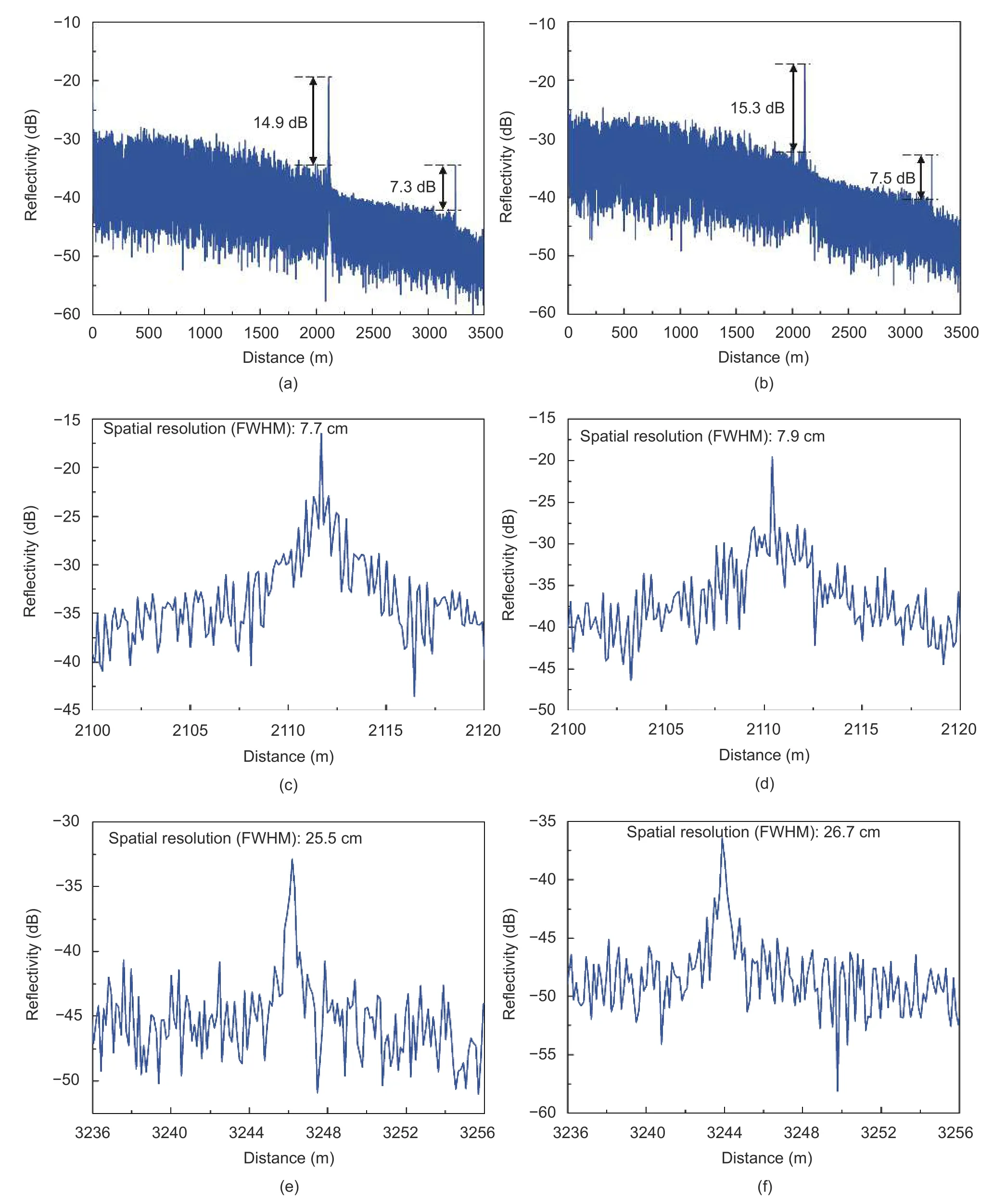
Firstly,the performance of the proposed OFDR scheme without the nonlinearity compensation was tested.As a comparison,the performance of OFDR after the software-based nonlinear phase compensation was also tested.The nonlinear phase compensation was realized by adding an auxiliary interferometer in Fig.1 and using the deskew filtering algorithm[20],which was carried out by using the LabVIEW platform.In the deskew filtering algorithm,a frequency tuning nonlinear phase estimated by using the auxiliary interferometer was used to compensate for the nonlinearity effect on the beating signals in the main interferometer.FUT was composed of two sections of optical fibers,where the first one was with a length of 2110 m and the second one was with a length of 1130 m.Figs.4 (a),(c),and(e) show the experimental results after the softwarebased nonlinear phase compensation.Figs.4 (b),(d),and (f) present the experimental results without the nonlinearity compensation.It can be seen from Figs.4(a) and (b) that two Fresnel reflection peaks are clearly obtained in both cases.The locations of the two reflection peaks after the software-based nonlinear phase compensation deviate from 2110 m and 3240 m due to uncertainty of the time delay in the auxiliary interferometer,which is a critical parameter in the deskew filtering algorithm to obtain the exact location.SNRs of the two reflection peaks are 15.3 dB and 7.5 dB in the proposed scheme,respectively,which are even a bit higher than the values of 14.9 dB and 7.3 dB obtained after the software-based nonlinear phase compensation.In addition,the spatial resolution for the two reflection peaks is 7.9 cm and 26.7 cm,respectively,which are close to the values of 7.7 cm and 25.5 cm obtained after the software-based nonlinear phase compensation.Therefore,it can be concluded that the proposed OFDR scheme can achieve high-resolution and high-SNR measurement without the nonlinear phase compensation.

Fig.2.Frequency-time diagram of the linear frequency modulated signal generated by DDS.

Fig.3.Optical spectra before and after CS-SSB modulation for a single-tone input microwave signal with a frequency of 6 GHz.
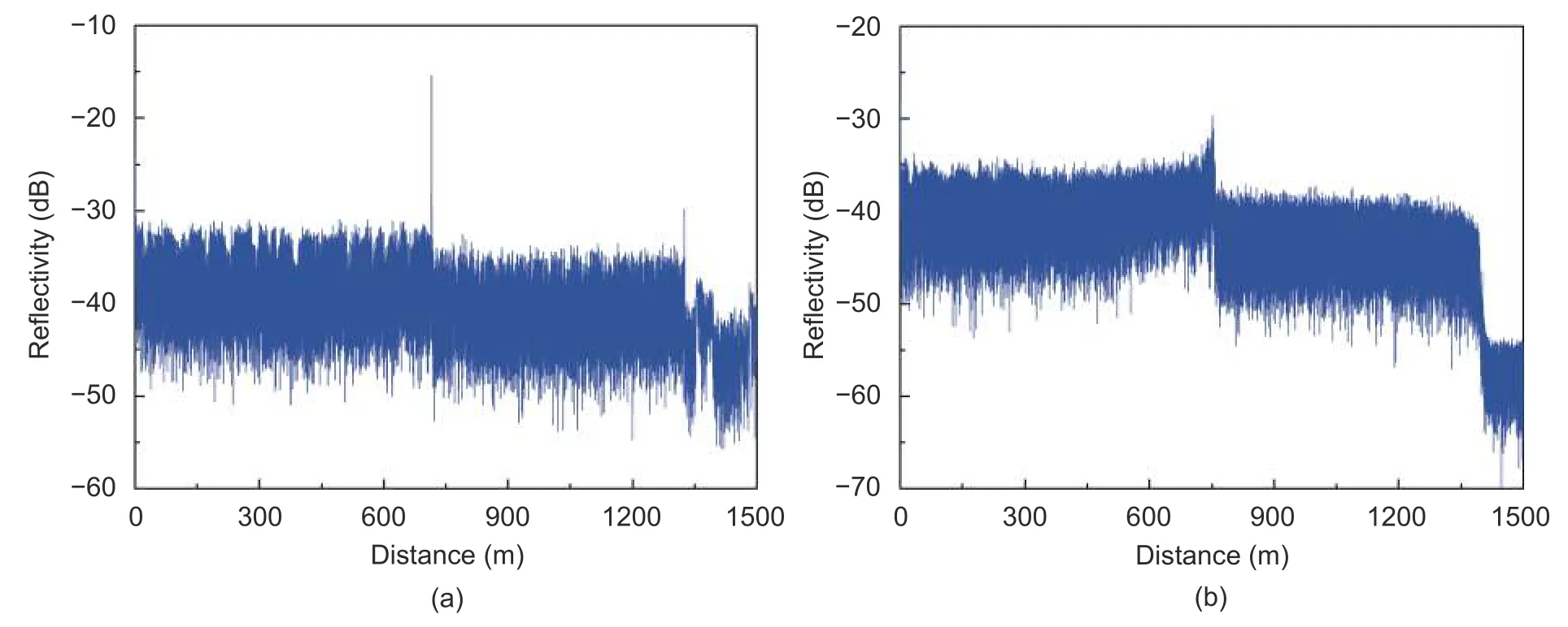
Then,the performance of OFDR based on commercial TLS was tested.The fiber laser source employed above also can generate a linear frequency sweep light.In the experiment,the frequency sweep rate and sweep time were set to 400 GHz/s and 20 ms,respectively.FUT was also composed of two sections of optical fibers,where the first one was with a length of 715 m and the second one was with a length of 609 m.Figs.5 (a) and (b) exhibit the experimental results after the software-based nonlinear phase compensation and without the nonlinear phase compensation,respectively.It can be seen from Fig.5 that the nonlinear phase compensation is indispensable to achieve high-resolution and high-SNR measurement when commercial TLS is used in OFDR.

Fig.4.Experimental results of proposed OFDR:(a),(c),and (e) after the software-based nonlinear phase compensation by adding an auxiliary interferometer and using the deskew filtering algorithm;(b),(d),and (f) without the auxiliary interferometer and nonlinear phase compensation.

Fig.5.Experimental results of OFDR based on commercial TLS:(a) after the software-based nonlinear phase compensation and (b) without the nonlinear phase compensation.
4.Conclusion
In summary,we proposed and experimentally demonstrated nonlinearity-compensation-free OFDR based on the electrically-controlled optical frequency sweep.A linear frequency sweep optical signal was generated by propagating an ultra-narrow-linewidth CW light through an electro-optic frequency shifter driven by a linear frequency modulated signal from DDS.The prominent advantage of the proposed scheme is that only a single interferometer is needed,which greatly simplifies the measurement setup.In the experiment,the linear frequency sweep light with the linearity of 1.57% was generated and used to achieve OFDR.The spatial resolution of the proposed scheme is 7.9 cm and 26.7 cm at the two obtained reflection peaks,respectively,while SNRs are 15.3 dB and 7.5 dB,which are comparable to those of OFDR employing commercial TLS and an auxiliary interferometer after the software-based nonlinear phase compensation.Thus,without the auxiliary interferometer and nonlinear phase compensation,the proposed OFDR scheme has the ability to achieve high-resolution and high-SNR measurement,simplifying the optical structure and eliminating the difficulty of developing the nonlinear phase compensation algorithm.
Disclosures
The authors declare no conflicts of interest.
 Journal of Electronic Science and Technology2021年1期
- Journal of Electronic Science and Technology的其它文章
- Signal Acquisition and Processing Method for Capacitive Electromagnetic Flowmeter
- lmage Classification with Superpixels and Feature Fusion Method
- Bioinformatics Analysis on lncRNA and mRNA Expression Profiles for Novel Biological Features of Valvular Heart Disease with Atrial Fibrillation
- Identification of the Potential Function of circRNA in Hypertrophic Cardiomyopathy Based on Mutual RNA-RNA and RNA-RBP Relationships Shown by Microarray Data
- lmpact of Coronavirus Pandemic Crisis on Technologies and Cloud Computing Applications
- Molecules against COVlD-19: An in Silico Approach for Drug Development
