
Analytical Description of M-Shape Sound Beams*
2021-03-11 03:10:06
电子器件 2021年6期
(School of Electronic Science and Engineering,Southeast University,Nanjing 210096,China)
Abstract:In this paper,new families of sound beams are presented,which produce the sound fields with an axialsymmetric amplitude distribution like the capital letter“M”and are termed the M-shape waves.A simple mathematical description is derived for two situations:infinite aperture and finite aperture.The beam distributions in the field of the M-shape sound source are computed on the acoustic axis and at various cross sections.A numerical example is given for a hypothetical transducer with 2.5 cm radius,1 MHz center frequency and the Hermite coefficient B2=4,this transducer will radiate M-shape beam within the regions of about 10 cm from the source and the field pattern is relatively uniform at the ranges of about 10 cm behind this distance.Possible applications of M-shape beam in some areas such as hyperthermia and advanced imaging techniques,are also discussed.
Key words:propagation of ultrasound;beam pattern;ultrasonic transducer;analytical description
In 1959 von Haselberg and Krautkramer presented the design of Gaussian ultrasonic transducers using the star-shape-electrode method[1],since then,a variety of transducers which can produce the sound fields with special distributions in the radial direction at specific ranges in media,have gradually attracted close attention.The transducers on the surface with the vibration velocity distributions such as Gaussian,annular andJ0Bessel functions are widely investigated and applied in the many areas of ultrasonic measurement,medical ultrasound and ultrasonic imaging for biological tissue samples.[2-8]In the particular case of hyperthermia,i.e.,the use of heat in cancer therapy by ultrasound,in order to provide a uniform heating in tissues Hynynen et al.[6]suggested to employ a kind of ultrasonic transducer,whose intensity distribution on the radiating surface is shown in Fig.7 in Ref.[5].It is required that the beam pattern is low at the center and high at the edges of heating area.Harrison et al.designed and fabricated ever a series of transducers by means of the star-shapeelectrode method(so-called asteroidal approximation)and other techniques,moreover,they estimated and measured the sound fields generated by the transducers,some of which are quite similar to the transducer imagined by Hynynen et al.However,the mathematical description for sound fields of these transducers is much complicated,in reality,which is the same as for the piston source without simple analysis,especially in the nearfield and the transition zone.The sound beam distributions are usually determined by numerical computations(the point-by-point integration according to the well-know Rayleigh integral),it will be much more complex to further deal with the hyperthermia and other effects caused by the ultrasonic fields in biological tissues.
In this paper,we report a new class of sound fields for which the beam pattern on the sources resembles with the capital letter“M”,and term them M-shape waves or M-shape sound fields.Correspondingly,this kind of sound sources are named the M-shape ones(or transducers).In addition,because the on-source beam distributions can be described with the Hermite functions or their combinations,sometimes we refer to them as the Hermite sound beams.In this study,we first introduce the families of M waves and derive a relatively simple and universal representation for this class of M sound beams,furthermore,we analyze and calculate chiefly the case of the second-order M sound field.Next,we compute the sound fields generated by the second-order M wave with a finite aperture,and compare with those for the infinite aperture.We suggest that like the single annular transducer and others,the ultrasonic field of the M-shape transducers could be also utilized in cancer therapy by ultrasound.
1 Theory of Infinite Aperture M-Shape Beam
Intuitively,when the geometric size of a sound source is much greater than the wavenumber of sound in the medium,that is to say,under the conditionka≫1,the sound source with one specific function distribution radiates a sound field,at least,the nearfield distribution should roughly approximate to the profile of this function,although there are some diffraction effects in the propagation of sound.Consequently,a natural idea is that in order to produce an M-shape sound field one may make the pressure amplitude distribution on the source be or approach an“M”shape by the special design of transducer.For example,the choice of a single annular source is acceptable[5],however,like the piston,the sound beam in the nearfield does not have the representation of analysis.It will be seen that for the sources with the profiles of the functionsxne-x2(Fig.1)which are called the M-shape functions or Hermite functions in this paper,as shown in Fig.1,not only do these sound fields have the M-shape distribution in the regions near the source(in the nearfield),but also they can be described in a simply mathematical analysis.
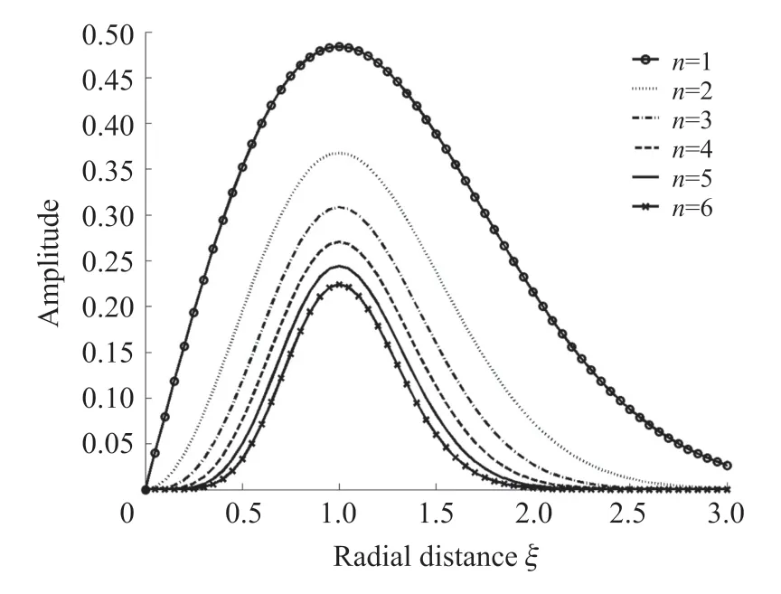
Fig.1 M-shape or Hermite function distribution
1.1 Wave Equation and Infinite Aperture M Waves
A convenient approach which treats the propagation of sound waves radiated by an axial-symmetric sound source in the medium is to solve the linearized KZK equation.Under the parabolic approximation,a form of this equation can be written in the nondimensional form:[9]
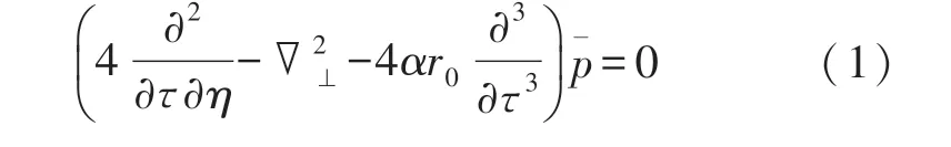
The description for sound fields governed by Eq.(1)is excellently accurate at very large propagative ranges except extremely close to the source(the same order of source radius).Here,¯p=(p-p0)/ρ0u0c0is the dimensionless pressure,or the normalized one,pis the pressure,ρ0the density of medium,andc0the sound speed,whilep0is the ambient value of the pressure.randzrepresent the radial and axial coordinates,correspondingly,ξ=r/aandη=z/r0are the dimensionless radial and axial distances.r0=ka2/2 is the Rayleigh distance,k=ω/c0is the wavenumber of sound,whileωis an angular frequency of sound source.In addition,ais a characteristic radius of the sound source.For example,ais the radius of the piston source.τ=ω(t-z/c0)is the normalized retarded time,tthe time.αis the absorption coefficient of sound waves at the angular frequencyω.denotes the nondimensional transverse Laplace operation with respect toξ.
The general solution of Eq.(1)for an arbitrary axial-symmetric distribution source which oscillates sinusoidally in time is,in terms of nondimensional variables,
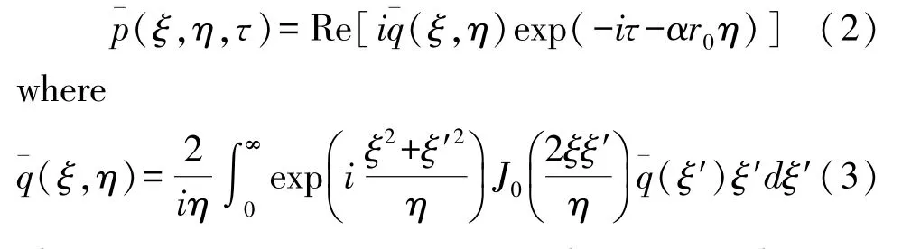
There are some unimportant differences between Eq.(3)and Eq.(2)only in the phase factor and absorption term.For brief,we assume the absorption of sound may be neglected,and directly use Eq.(3)to describe the pressure field.As a rule,Eq.(3)can be viewed as the complex amplitude of the normalized pressure and ¯q(ξ′) is termed the source distribution function.
Suppose now that the amplitude distribution of the M-shape(Hermite)sound wave on the source is expressed in the following:
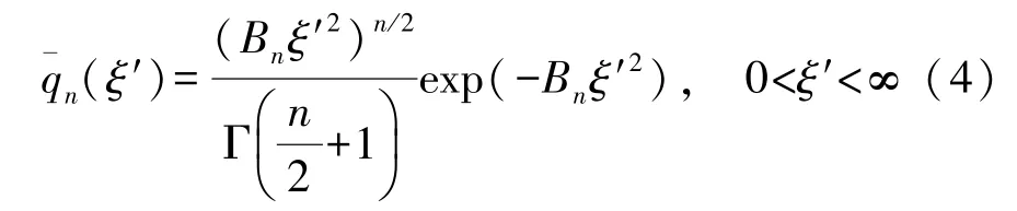
where Γ represents the gamma function and the subscriptnis the order number,Bn=.Bnis relevant to the characteristic radiusa(in practical cases,amay be taken as the radius of the M-shape transducer)anda0that is the distance at which the pressure is maximum from the source center,as shown in Fig.1.Generally,we callBnorB′nthe Hermite coefficients of thenth-order M sound source.
Substituting Eq.(4)into Eq.(3),we have
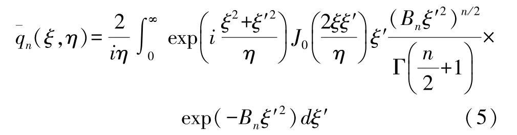
Using the following formula(6)
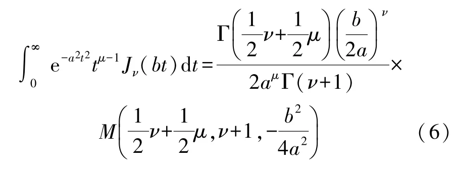
and the Kummer transformation
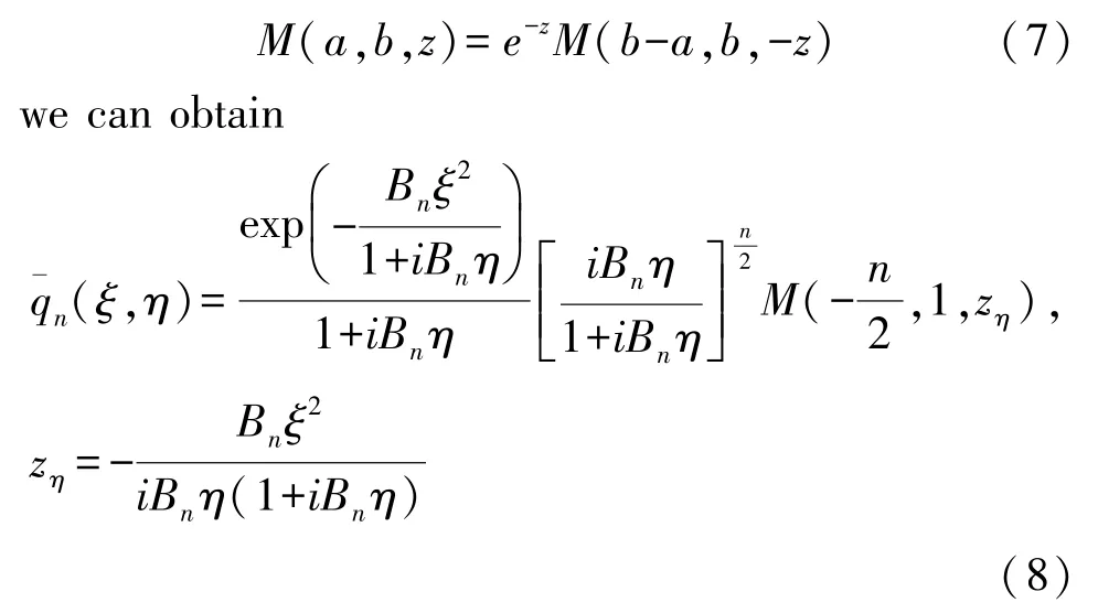
whereM(a,b,z) is the confluent hypergeometric function that has a form of series expansion
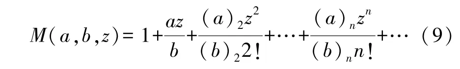
in which(a)n=a(a+1)(a+2)…(a+n-1) and (a)0=1[10].Without loss of generality,for an M sound source with infinite aperture,we adopt another pair of coordinate variablesXnandZn:
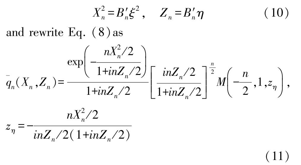
Particularly,whennis an even integer,the functionM(-n/2,1,z)will become the polynomial with respect toz,in fact,which is the Laguerre polynomial.For an odd integern,this function is a series of infinite terms defined by Eq.(9).We divide further the M-shape(or Hermite)sound fields into two kinds:For an evenn,we term them thenth-order M waves of the second kind,and for an oddn,thenth-order M waves of the first kind,respectively.It can be known that the“M”waves of the second kind,like Gaussian beams,can be analytically described in an extremely simple manner,becauseM(-n/2,1,z)is a polynomial aboutz.More importantly,from Fig.1,we can see that for different order numbersn,the pressure amplitude profiles of M waves are almost similar,except for slight change in the widths of sound beam.Hence,we may choose a specific value ofnto recognize the features of the M-shape sound fields in the general case.In the following,we will mainly examine the second-order M sound beam(n=2),which is the simplest example.Some general characteristics of thenth-order M beams are presented in Appendix.
1.2 Second-Order M Sound Beam
Whenn=2,Eq.(8)simplifies to
or in another form
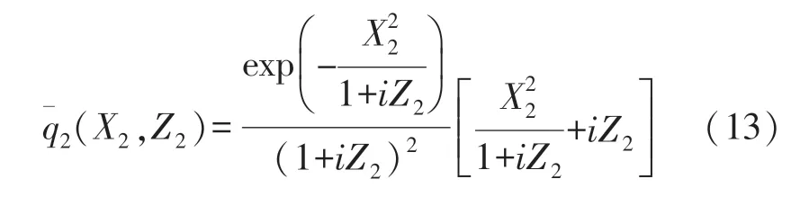
The pressure amplitude distribution is then expressed by
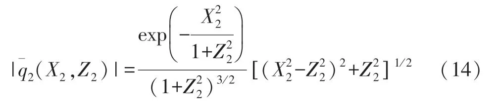
AtX2=0,i.e.,on the acoustic axis,the pressure amplitude becomes
Here we always refer toX2=0 as the center(or central line)of the M sound source(or beam).For clarity,we calculate the amplitude distributions of the second-order M sound beam,which are plotted in Figs.2 and 3.
Because the description of the second-order M wave is especially easy in mathematics,the properties of sound field can be obtained by algebraic operation.We introduce
and
These two equations determine the positions of the maxima and minima of pressure amplitude in a section planeZ2.From Eq.(18),we can know that the amplitude maxima,called the amplitude peaks of M-shape sound field,are located on the lineOn this line,the pressure amplitude is
For convenience,we introduce a parameter(X2w),which describes the beamwidth of the M-shape sound field and is simply defined as the distance between two peaks in a planeZ2.According to(18),we obtain the half-beamwidth with the distanceZ2as follows:
Similarly,we can see from Eq.(19)that on the line,the pressure amplitude takes the minimum values which we refer to as the troughs of the M-shape sound beam and this amplitude distribution can be described by
WhenZ2=0,we getX2=0 from Eq.(19),this represents the trough position for M-shape sound source.On the source,the center coincides exactly with the trough of the M sound beam.It should be noted that from the field profiles indicated in Fig.2,the peaks do not occur in all the range and the pressure amplitudes on the central line are not always lower than those on the lineIn other words,the amplitude profiles in the M-shape sound field remain an M-shape only in certain ranges.This distance can be easily determined.Let the pressure amplitudes on these two lines be equal,namely,

Fig.2 Radial beam distributions of the second-order M sound field with an infinite aperture
then we haveZ2=1/e(denoting it toZe)and call the transition distance of the M-shape field.The field profile at this cross sectionZeis shown as the curve forZ2=0.368 in Fig.2.In the zone from the source(Z2=0)to the planeZe,the pressure amplitude peaks decrease slowly while the pressures along the beam center and the trough lines increase gradually,the beam pattern is primarily similar to an M-shape,this zone is defined as the nearfield of the M-shape sound beam.When the beam propagates behind the planeZe,the central pressure amplitude increases and reaches maximum value at theZ2=1 which is defined to the farfield distance of the Mshape beam and denoted byZg.The range fromZetoZgis then termed the transition zone where the central pressure are greater than those on the linesFrom Figs.2 and 3,we can see that for an infinite aperture M wave,as it travels in the nearfield and the transition zone,the sound beam does not almost spread.In the nearfield,the beamwidth changes only by about 7%.WhenZ2>1 the central pressure begins to decrease,and with increasing the propagation distance the radial pressure distribution approaches a Gaussian function,as shown by the curve ofZ2=2 in Fig.2.This range can be considered as the farfield of the M-shape beam,andZ2=1 is referred to the farfield distance.Two distances,ZeandZg,are termed the characteristic parameters for this field or transducer.In practical design of the M-shape transducer required,it is convenient to determine the field regions where the beam profile has an M-shape and the farfield distance through these two parameters in order to choose the radius and the Hermite coefficient of the transducer.
2 Finite Aperture M-Shape Sound Beams
Real sound beams are always produced by the radiators with finite aperture,in other words,the dimension of sources is usually finite.For the M waves with finite aperture,the source distribution function can be expressed by
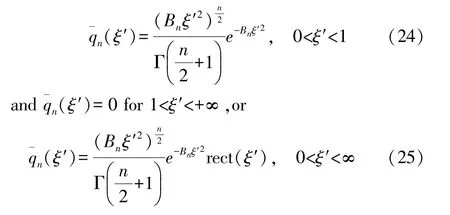
where rect(ξ)is the rectangular function defined by
Then,the field distribution can be given by
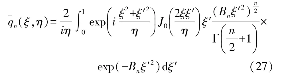
In general,Eq.(27)cannot be analytically integrated out.To describe the sound field distribution,it is required to make a complicated integration with numerical technique.Now we employ another approach,which can simplify this problem,and express rect(ξ′)as follows:[11-12]
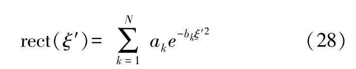
where the coefficientsakandbkhave been determined by the Wen’s or Ding’s methods.Of course,Eq.(28)is approximately valid,converging averagely the rectangular function in all the range[0,+∞).Then,Eq.(27)reduces to
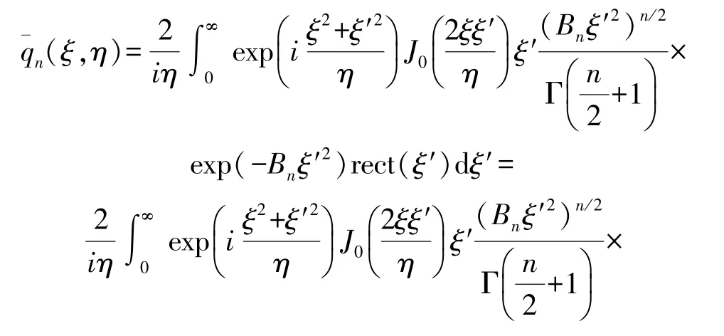
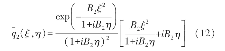
in whichBnk=bk+Bn.
Here we consider only the second-order M-Shape sound beam of finite aperture.For an actual transducer,the choice of differentB2values matches to truncate an infinite aperture M source with different apertures.WhenB2<1,the beam distributions on the truncated source are almost the same as forB2=1 so that we take typicallyB2=1,2,and 4,this corresponds toa/a0=1,1.414,and 2.As indicated already,ais a radius of the sound source or the transducer,a0is the distance for the maximum pressure amplitude whenB2is greater than or equal to 1.In such an example ofB2=1,the truncated aperture radius is just equal to the half-beamwidth of the second-order M-shape source with an infinite aperture,namely,a0=a.The beam distributions are calculated from Eq.(29)and drawn in Fig.3.It can be known that due to the“truncated effect”of source,there are many ripples in the sound field,except for the original peaks and troughs of pressure amplitude.In comparison with the infinite aperture M sound beam,there exists a considerable difference for the field distributions of finite aperture,especially whenB2is relatively small.For the large values ofB2(B2=4),however,this distinction is not very obvious and the beam distribution of finite aperture is basically the same as the case of infinite aperture,a comparison is not shown here.Of course,we may select such a coefficientB2=4 in the design of the Mshape transducer that we can describe yet the sound field of the transducer with this coefficient using the theory of the infinite aperture M-shape sound field.This could simplify theoretical analysis of hyperthermia effect and others by ultrasound in tissues,just like in most cases that Gaussian transducer fields in practical applications can be easily described by the theory of Gaussian beam with infinite aperture.
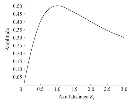
Fig.3 Axial beam distribution of the second-order M sound field with an infinite aperture
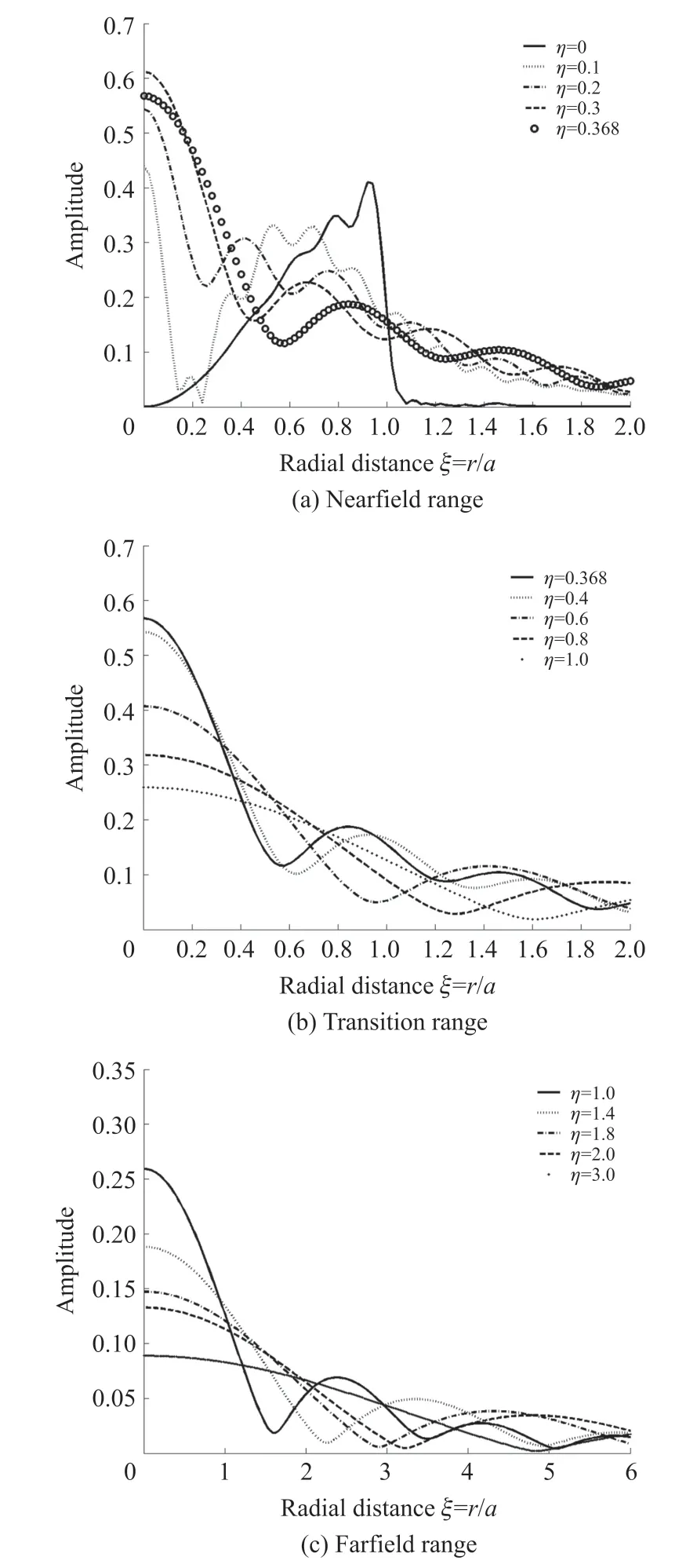
Fig.4 Radial beam distributions of the finite aperture second-order M-shape fields with Hermite coefficient B2=1
3 DISCUSSION
Hynynen et al.estimated the radial temperature distribution at the distance of 10 cm from the transducer that has a hypothetical intensity distribution on the surface,and found this intensity distribution causes a uniform temperature rise in radial regions after about 30 minute heating in the tissue.Noting the M-shape intensity distributions on the source are much similar to that they imagined,it is certain that this M-shape beam can provide the identical effect in hyperthermia.It has been shown that in medical ultrasonics,usually,the operation frequencies of transducers employed are about from 1 to 10 MHz,about 1 MHz-frequencies are found to be most useful for hyperthermia.[6]As an example,we provide a computer simulation of the intensity distribution for a finite aperture M sound field.We assume that the M-shape transducer has the diameter of 5 cm(ora=2.5 cm) anda0=1.25 cm.(From the definition of Hermite coefficientBn,in this case,B2=4).The center frequency of this transducer is 1 MHz and the sound speed of the medium(water)is about 1 500 m/s.The nearfield and farfield distances are approximated to 12 and 32.7 cm respectively.The sound intensity distributions are depicted in Fig.5.Very obviously,these distributions are very much similar to the results in Fig.7 of Ref.[5].The beam intensity profiles in the region of about 10 cm from the transducer surface have an M-shape.Besides,as pointed out by Harrison et al.,a wide constant-amplitude beam profile would be useful in advanced imaging techniques such as holography or in advanced tissue characterization schemes using deconvolution.This kind of M-shape source generates relatively uniform amplitude distribution in the transition zone(about from 10 to 20 cm along the propagation axisz),as shown in Fig.5,it could be utilized in holography and other imaging techniques.
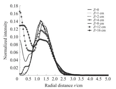
Fig.5 Relative beam intensity distribution
Finally,we should point out how to realize the transducers for generating the M-shape ultrasonic beams.In principle,ones may control the amplitude profile of a sound wave radiated by a transducer in several ways such as the star-shape-electrode and curved-backelectrode methods.It has been shown that the curvedback-electrode method is simple and efficient to obtain desired beam profiles on the transducer surface.In next part of this study,we will employ this approach to realize this kind of M-shape transducers and test experimentally the sound field distributions.
4 SUMMARY
We have developed a class of M sound sources that may provide a novel way to generate sound beam applied in hyperthermia by ultrasound.The mathematical description for infinite aperture M beams is analytically obtained.Also,the“truncated”finite aperture M beams are addressed.The M-shape sound field is possibly applicable in the different conditions.The beam distribution in the nearfield of the transducer is very much similar to that suggested by Hynynen et al.,it may be used to produce a uniform heating in tissues.The transition field distribution is relatively uniform in the radial direction,it may be useful in imaging techniques that need a uniform lateral field distribution within a narrow beam.Furthermore,the curved-back-electrode technique is being investigated to design transducers that yield the M-shape pressures distribotions.
APPENDIX:The nth-Order M-Shape Beam
1 Axial Beam Distribution
No matter thatnis an even or an odd number,due toM(a,b,0)=1,it always follows
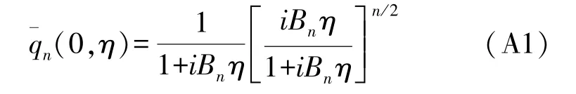
whenξ=0.This is the normalized complex amplitude distribution of thenth-order M-shape beam along the acoutic axis.
2 Farfield Distribution
For largeBnη,|zη|is small.Assuming |zη|→0,thenM(a,b,z)→1,we have the the beam distribution in the farfield as follows:
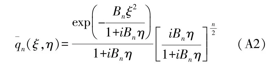
Here,it has been assumed thatBnξ2is small in comparison withBηin Eq.(8).
3 Nearfield Distribution
For large |z|,M(a,b,z)has an asymptotic expansion
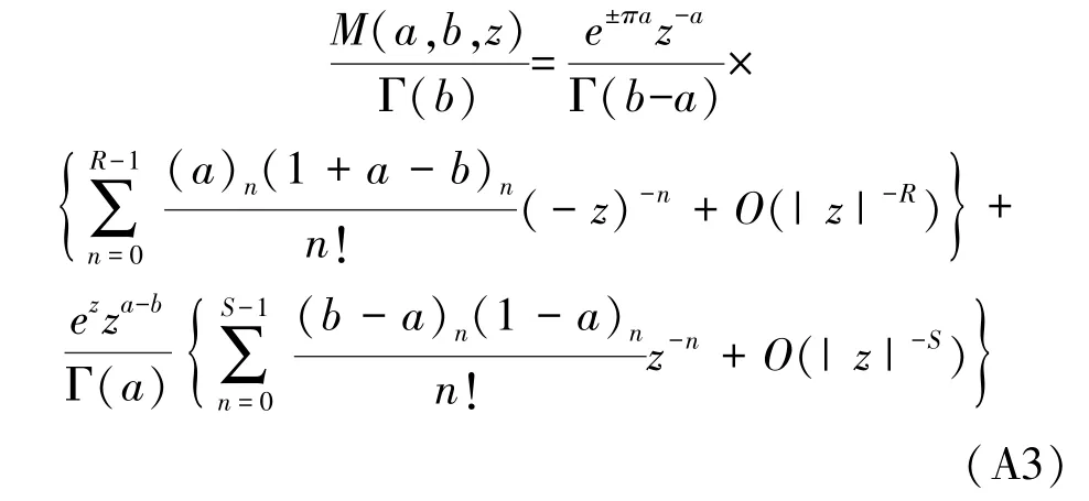
In the case when the beam propagates in the nearfield,Bnηis small and |zη|is large,we may use(A3)to calculate the nearfield beam distribution by choosing appreciateRandS.A small number of terms suffice to give the accurate results of the nearfield distributions.It may be proven thatη→0,the distribution approximated from this expression will approach Eq.(4)describing the on-source beam distribution.
In fact,whennis an even number,M(-n/2,1,z)transforms to a polynomial,as pointed out in the text.The above approximate expressions are useful on the condition thatnis not even numbers(the M-shape sound beam of the first kind).It is easy to verify that the M-shape sound field for arbitrary value of the numbernhas the beam pattern much similar to the second-order M-shape field.
