Assessing the microstructure and in vitro degradation behavior of Mg-xGd screw implants using μCT
Din Krügr ,Brit Zllr-Plumhoff ,Björn Wis ,Sngong Yi ,Mrcus Zur ,D.C.Florin Wilnd ,Julin Moosmnn,Rgin Willumit-Römr
a Institute of Metallic Biomaterials,Helmholtz-Zentrum Hereon,Max-Planck-Str.1,Geesthacht 21502,Germany
b Institute of Material and Process Design,Helmholtz-Zentrum Hereon,Max-Planck-Str.1,Geesthacht 21502,Germany
c Institute for Photon Science and Synchrotron Radiation,Karlsruhe Institute of Technology,Herrmann-von-Helmholtz-Platz 1,Eggenstein-Leopoldshafen 76344,Germany
dLaboratory for Applications of Synchrotron Radiation,Karlsruhe Institute of Technology,Kaiserstr.12,Karlsruhe,Germany
e Institute of Materials Physics,Helmholtz-Zentrum Hereon,Max-Planck-Str.1,Geesthacht 21502,Germany
Abstract Biodegradable implants are taking an increasingly important role in the area of orthopedic implants with the aim to replace permanent implants for temporary bone healing applications.During the implant preparation process,the material’s surface and microstructure are being changed by stresses induced by machining.Hence degradable metal implants need to be fully characterized in terms of the influence of machining on the resulting microstructure and corrosion performance.In this study,micro-computed tomography(μCT)is used for the quantification of the degradation rate of biodegradable implants.To our best knowledge,for the first time quantitative measures are introduced to describe the degradation homogeneity in 3D.This information enables a prediction in terms of implant stability during the degradation in the body.Two magnesium gadolinium alloys,Mg-5Gd and Mg-10Gd(all alloy compositions are given in weight% unless otherwise stated),in the shape of M2 headless screws have been investigated for their microstructure and their degradation performance up to 56 days.During the microstructure investigations particular attention was paid to the localized deformation of the alloys,due to the machining process. In vitro immersion testing was performed to assess the degradation performance quantified by subsequent weight loss and volume loss(using μCT)measurements.Although differences were observed in the degree of screw’s near surface microstructure being influenced from machining,the degradation rates of both materials appeared to be suitable for application in orthopedic implants.From the degradation homogeneity point of view no obvious contrast was detected between both alloys.However,the higher degradation depth ratios between the crests and roots of Mg-5Gd ratios may indicated a less homogeneous degradation of the screws of these alloys on contract to the ones made of Mg-10Gd alloys.Due to its lower degradation rates,its more homogeneous microstructure,its weaker texture and better degradation performance extruded Mg-10Gd emerged more suitable as implant material than Mg-5Gd.
Keywords: Magnesium alloys;Biodegradable implant;Degradation rate;Degradation homogeneity;Micro-comptued tomography.
1.Introduction
Magnesium(Mg)and its alloys are already successfully introduced into the clinics for example by the company“Syntellix AG”[1]as biodegradable temporary orthopedic implants due to their optimal strength and adjustable corrosion rate[2,3].The biodegradation of such implants during the healing period [4]would prevent a second,costly,and risky implant removal surgery after the fracture has healed.The requirement of biodegradation is fulfilled both by biodegradable metals and biodegradable polymers.However,it has been proven that the mechanical properties of biodegradable polymeric implants significantly decrease in physiological environments,thus limiting them as load bearing implants [2].In addition to available zinc or iron-based metallic degradable implants,implants made of Mg alloys exhibit better implant stability.Mg alloys possess an increased biocompatibility along with the suppression of inflammatory cascades,tissue loss [5]and stress shielding effects which reduces the bone growth stimulation and bone remodeling [5].Mg ions released in the body do not cause cellular toxicity if they are below a critical concentration and are expelled along with urine [6].In addition,Mg is essential to human metabolism as a cofactor of many enzymes and facilitates tissue-healing [7].
Since pure Mg alone does not provide sufficient strength for load-bearing applications,alloying elements are added such that the mechanical properties of the alloys are suitable for implant applications.As a consequence of the alloying,the implant’s density,elastic modulus,and yield strength can be tailored close to those of human bone [7].The addition of rare earth elements(REE)to a high purity Mg matrix results in promising biodegradable Mg alloys.Such alloys exhibit sufficient strength and toughness,rendering them useable for load-bearing applications [8,9].Significant effects of solid solution strengthening have been observed in Mg-gadolinium(Gd)alloys in particular [10].When alloying Gd to Mg for application as implants,the toxicity of Gd and its possible harm has to be taken into account,since it can accumulate in animal organs [11,12].However,it was previously shown that the release of Gd from Mg-xGd alloys is below the critical toxicity level and these alloys are suitable candidate for medical usage [13–16].Additionally,Mg-10Gd alloys have displayed good cytocompatibility and were shown to improve the osteoblast-induced mineralization [17].Previously it has been shown that the addition of up to 10 wt%(wt.%)Gd to the Mg-matrix decreased the degradation rate [18].The degradation rate increased again when increasing the Gd content in the alloy.One of the important effects of REE on the corrosion resistance of Mg is the so-called“scavenger effect”,which means that the influence of impurities in the Mg matrix,like iron(Fe),can be suppressed due to the formation of the intermetallic phases between the REE and the impurity [19,20].Previously,gadolinium hydride(GdH2)particles have been observed in Mg-Gd alloys [10].They are being formed in presence of a hydrogen containing medium and after a sample deformation has taken place [21].During the alloy production,potential hydrogen sources are Mg with its high hydrogen storage capacity [22],and contaminations of Mg or Gd with H-containing compounds.The agglomerations of GdH2may serve as small galvanic cells in the alloy.
Recently,Mg has been investigated as an alloying element in Fe-based implant material,where Mg played the role of the degradation accelerator [23].Although degradation rates suitable for bone implants were achieved for the Fe-20Gd solid solution,prepared by mechanically driven supersaturation,it is less conventional and more complicated,than the currently presented casting of Mg-xGd alloys.Casting is the most common approach in Mg bone implants fabrication,since it enables the easy control of the alloy composition,it is convenient to operate and it is not expensive [24].
Depending on their mechanical properties and microstructure,the investigated implants reveal deformation zones and twinning zones differing in thickness as a result of machining.Previously,Gawlik [25]reported that during acidic etching of Mg-xGd a tendency of increased material removal from the surface with increasing Gd(2,5 and 10 wt.% Gd content)is observed.It was hypothesized that the alloys’ thicker twinning zone with lower Gd content might have slowed down the dissolution rate at early stages.Since the twinning zone of Mg-10Gd was smaller,the un-twinned bulk material would have been reached much faster.
Due to the influences of the alloy’s microstructure on the implant’s degradation performance,we aim to link the microstructure of Mg-xGd(x=5 or 10 wt.%)implants after fabrication into a screw shape to their degradation velocity over 1–56 days in cell culture media using the advantages of non-destructive 3D imagingviaμCT.The microstructure itself is investigatedviaelectron backscatter diffraction(EBSD)and optical microscopy(OM).
Commonly,the investigation of the biodegradation is performed using weight loss experiments.Weight loss is one of the most low-cost and simple experiments that provides accurate and clearly defined data that is simple to set up,perform,and control [33].However,this method’s disadvantages are that it does not provide any information on the corrosion mechanism,the time-dependent corrosion behavior,and multiple samples are needed to have a sufficiently low statistical error.Liu [34]have already shown that degradation rates of different materials measuredviaweight loss and volume loss using μCT are similar.We are additionally exploring the potential of μCT to determine degradation parameters such as the pitting factor by using the full three-dimensional information,as previously demonstrated [35].By calculating parameters both in 2D and 3D,we are able to study the localized degradation of implant screws non-destructively.This may allow a prediction in terms of implant stability during the degradation in the body.
2.Materials and methods
2.1.Materials/ samples
Two Mg alloys with 5 and 10 wt.% Gd(Mg-5Gd,Mg-10Gd)were investigated in the current study.Melting and casting were performed by permanent mold direct chill casting using Ar+3 vol.% SF6as shielding gas in the induction furnace(Typ K 10/S 1,Nabertherm,Lilienthal,Germany).5 or 10 wt.% Gd was added to the Mg melt at 700 °C and stirred for 20 min with a rotation speed of 150 min−1.The molten materials were then poured into a permanent steel mold(diameter 110 mm,height 230 mm),which was preheated up to 680 °C and kept for 15 min.Afterwards,the ingots were cooled down by water quenching.They were solution heat treated(T4)at 525 °C for 6 h and cooled down again by water quenching.Indirect extrusion was performed with an extrusion ratio of 84 to the final diameter of 12 mm.A ram speed of 0.7 mm/s for Mg-5Gd and 0.52 mm/s for Mg-10Gd and a temperature of 400 °C were used for extrusion.Rods with a diameter of 3 mm were cut from the extruded barsviawire electrical discharge cutting.Finally,headless screws were machined by turning and by milling the slit.The screws measured 4 mm in length,2 mm in diameter,had an M2 thread and a 0.5 × 0.5 mm slot.
2.2.Microstructural observations
Bulk material and screws were cold embedded in an epoxy resin(Demotec 30®,Demotec Demel e.K,Nidderau,Germany),manually grinded and polished for the microstructure analysis.The grinding process was performed from 500 to 2500 grit SiC sandpapers.The polishing was performed in two steps.First by using SiO2(OPSTM,Cloeren Technology GmbH,Wegberg,Germany)with water(H2O),H2Ofree lubricant(ethylene glycol to ethanol in parts of 10:7)and sodium hydroxide(NaOH)for approximately 5 min.Second by using H2O-free SiO2(OPSTM,Cloeren Technology GmbH,Wegberg,Germany),diamond particle suspension with a 0.25 μm particle size with H2O-free lubricant(ethylene glycol to ethanol in parts of 10:7)for 15–20 min.
Following picric acid solution sample etching [36],observation of the microstructure was performed using an optical microscope(DMI5000 M,Leica,Wetzlar,Germany).The calculation of the grain sizes was performed on the bulk material,in longitudinal(extraction direction)and transversal direction of extrusion as well as on transversal sections of the screwviathe linear intercept method.As analysis software“analy-SIS Pro”(version 5,Olympus Soft Imaging Solutions GmbH,Münster,Germany)was used.
For the calculation of the deformation layer thickness on the optical micrographs three regions(root,flank,and crest)were defined(see Fig.3A).In these regions,the region near the surface with no definable grains or twins was separated from areas with visible grains or twins(see Fig.3C and D).The thickness measurement of the layer with no recognizable grains was performed in Fiji(ImageJ)[25].
Fig.1 shows the areas chosen for the investigation of the microstructural differences between the bulk(210 × 195 μm2)and surface near area of the screw,within the crests(310 × 200 μm2)and the roots(310 × 200 μm2)in particular.EBSD(SEM:Zeiss Crossbeam 550,EBSD detector:Oxford Symmetry)measurements were performed on one screw per material(1.5 pitches of the screws,whereby a pitch is the distance from the crest of one thread to the next crest).The EBSD image quality maps were used for the quantification of three different twin types(tensile,compression,and secondary twins).The twin type depends on its angle to the crystal’s c-axis(tensile twins:≈86°,compression twins:≈56°,secondary twin:≈38°)[37,38].Also,the pole figure of each scanned area was obtained.The deformed microstructures’ features were studied by analyzing boundary characteristics and misorientation among neighboring measuring points(pixel size or“step size”=0.4 μm).The kernel average misorientation(KAM),which represents the average misorientation between each pixel and its nearest neighbors,was calculated to study the subgrain structures.These are indicators of the strain locally accumulated at the corresponding area.
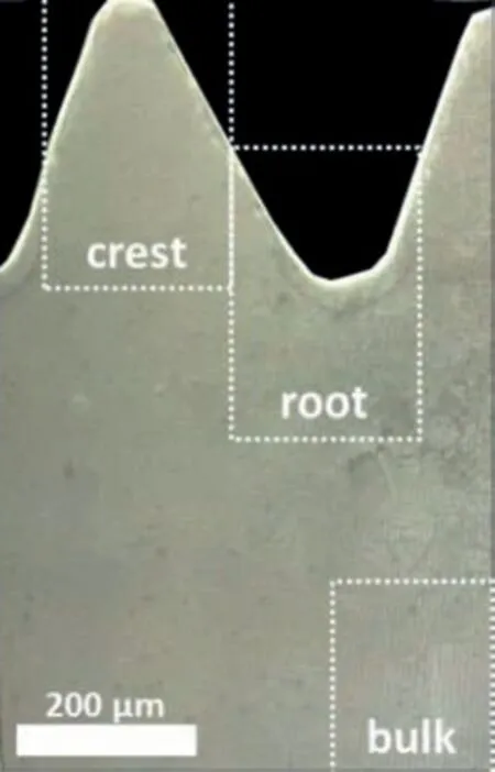
Fig.1.Exemplary areas of bulk,crests and roots on a Mg-5Gd screw for the EBSD measurements.
2.3.Immersion tests
The degradation rate(DR)was determined over a(i)short durations(1,3,6,7 and 9 days)and over two longer duration periods((ii)7,14,21,and 28 days and(iii)28,56 days)as a result of a semi-static immersion experiment.For experiments(i)and(ii)degradation medium ɑ-Minimum Essential Medium(ɑ-MEM;Thermo Fisher Scientific GmbH,Darmstadt,Germany)+10%Fetal Bovine Serum(FBS;PAA Laboratories,Linz,Austria)+1% Penicillin/Streptomycin(Thermo Fisher Scientific GmbH,Darmstadt,Germany)was used.For experiment(iii)the ɑ-MEM was replaced with DMEM(Dulbecco’s Modified Eagle’s Medium)to verify the small difference in the implant’s degradation behavior in these two media.
The immersion test was performed under cell culture conditions(37 °C,5% CO2,20% O2,95% relative humidity).To avoid saturation,the medium was changed every 2–4 days.The number of samples used for the weight loss and volume loss measurements per time point can be found in Table 6.
2.4.Micro-computed tomography(μCT)
Prior to immersion testing,the screws were imaged using a laboratory μCT(Phoenix Nanotom GE inspection andsensing technologies,Wunstorf,Germany)at an operating voltage of 100 kV at 70 μA current(binned pixel size:≈2.5 μm).Following the immersion tests and removal of the degradation layer by chromic acid treatment,the degraded screws from immersion test(ii)have been imaged either at the imaging beamline(IBL)P05 [39],which is operated by the Helmholtz-Zentrum Hereon,at the PETRA III storage ring at the Deutsches Elektronen-Synchrotron(DESY)(energy:25–30 keV,binned pixel size:≈2.6 μm)or at the TOPO-TOMO beamline of the KARA synchrotron facility at the Karlsruhe Institute of Technology(KIT)(energy:filtered white beam -max.intensity at 16 keV),binned pixel size:≈2.4 μm.The degraded screws from test(iii)have been imaged using the laboratory μCT after removing the degradation layer using the same treatment as described above.Additional information on the imaging parameters can be found in Table 9 in the appendices.For tomographic reconstruction at IBL,filtered backprojection(FBP)was used employing the ASTRA toolbox for the backprojection [40].Data pre-processing and tomographic reconstruction was done using the tomographic reconstruction pipeline at IBL [41,42].

Table 1 Segmentation methods and used softwares.
2.5.Image processing
Depending on the image quality,the segmentation was either performed on the original dataset or after the application of a filter.The chosen image filters,filter parameters,segmentation software,and method are presented in Table 1.Prior to the analysis registration of the corroded and not corroded implants on each other and an alignment to the z-axis of the 3D data parallel to the longitudinal axis of the screw were necessary;for an example of a transverse view see Fig.7.The image registration procedure determines the parameter values of a rigid body transformation to match an image to a reference image [43].The registered datasets are then resampled onto a common coordinate system with a voxel size of 5 μm.Resampling is the next step to the registration,which is the object’s actual transformation according to the determined parameters.All registration and resampling steps were performed in Avizo.

Table 2 Deformation layers thicknesses[μm]of processed Mg-xGd alloys in different areas of the screw.
The quantitative degradation parameters,as described in Sections 2.6 and 2.7,have been investigated in 2D and 3D,respectively.Degradation rate(DR)(described in Section 2.6)and mean degradation depth(MDD)(described in Section 2.7)were only calculated in 3D,volume loss only in 2D and pitting factor(PF)in 3D and in 2D .The same formulae of the 3D calculations were used in 2D calculations on each slice,resulting in statistical mean and standard deviation values for one sample.
2.6.Degradation rate(DR)
TheDRfor each immersion period was calculated with two methods:(1)weight loss and(2)volume loss measurements.The weight loss was measuredviaweighing the screws before immersion and after removal of the degradation layer with chromic acid.The volume loss,following μCT imaging,was determinedviacalculation of the screw volume before immersion and after removal of the degradation layer.Based on weight loss and volume loss measurements,the degradation rate was calculated as [48]:

where∆m[g]denotes the sample weight loss,∆Vthe sample volume loss,A[cm²]the initial surface area,ρthe material density(ρMg−5Gd=1.81 g/cm3,ρMg−10Gd=1.87 g/cm3),andtthe immersion time.For the weight loss measurements,a high precision balance(MYA 2.4Y Microbalance,Radwag Balances and Scales,Radom,Poland)was used.The volume from the μCT investigations was calculated with software Fiji(ImageJ)[44]and Avizo version 9.4.2(Thermo Fisher Scientific,Waltham,MA).For the weight loss(WL)calculations,the surface area of the screws was assumed to be the same for all screws and was theoretically calculated based on construction drawing(A=0.4125 cm2).For the volume loss(VL)measurements,the surface area of each screw was calculated with Avizo from the measured data.
For comparison with the literature,under the assumption of a uniform degradation,the mean degradation depth(MDD)for each immersion time was calculated by [48]:

It has been previously observed,that with increasing exposure times within one experimental setup theDRwas always decreasing([48,49,50]).Assuming a linear mean degradation depth increase with increasing exposure time a straight regression line was fitted to theMDDvalues.The slope of the fitted line is defined as the global degradation rate(GDR[mm/a]).The coefficient of determination(R2),which is a measure of the proportion of variance of a predicted outcome [51],was determined for the fitted regression lines,i.e.GDRs.It reveals how well a linear regression model fits the experimental results,where the value 1 would correspond to a perfect fit of the data to the regression line.
2.7.Degradation homogeneity analysis
Pitting factor(in 2D and 3D),volume loss in 2D and crest/roots ratio were selected as analysis parameters describing the degradation homogeneity.These are described in more detail in the following and were calculated for samples degraded between 7 and 56 days.
Pitting factor(PF)in 2D and 3D
The pitting factorPFifor a given sliceiof a given volume of interest(VOI)is defined by [52]:

whereDPiandMDDiare the deepest pit and the mean degradation depth within slicei,respectively,see Fig.7C.Note that this calculation is only possible for the slices where the degradation layer does not reach the center of the screw.The mean and the standard deviation of the pitting factor in 2D is then calculated as:

where N is the number of analyzed image slices.For the calculation of the3D-PFEq.(5)is used withDP[μm]being the deepest pit of the whole 3D implant andMDDthat of the whole 3D implant.Compared to the other parameters describing degradation homogeneity,the 3D PF parameter depends only on the deepest pit along the whole screw.Thus,this parameter has a sensitivity to the global non-homogeneous degradation behavior among also the same alloys.
Volume loss
Volume loss defines the degraded volume per image slice and is the difference between the not-corroded and the corroded screw.It can differ from the“degradation layer”,i.e.the layer of precipitates formed during the degradation process,since the volume of precipitates must not coincide with the degraded material,see Fig.7.Volume loss is calculated for each sliceialong the longitudinal axis of the screw as:

where the subscriptsncsandrsdenote the not corroded screw and the residual screw,respectively(Fig.7).
Gd-rich particles

Fig.2.2D image of Mg-5Gd screw imaged using μCT(A)before degradation(not corroded screw),(B)difference layer thickness as defined in Eq.(7),after 56 days in vitro degradation;the color bar in the images shows the image depth in voxel.
To segment the Gd-rich particles in the 3D tomograms,automatic thresholding in Fiji(ImageJ)followed by removal of single-pixel large particles in Avizo was performed.The amount,size,and distribution of Gd-rich particles in both alloys was calculated with different parameters in the chosen volume-of-interest(VOI)measuring 480×480×960 μm3:(1)the overall amount of detected Gd-rich particles;(2)overall volume of the Gd-rich particles [vol.%];(3)smallest distance between two Gd-rich particles [μm];(4)amount of detected outlier Gd-rich particles;(5)mean and standard deviation of the Gd-rich particles outliers from the 3D size distribution[μm3],(6)median of the Gd-rich particles from the 3D size distribution[μm3];(7)mean Feret diameter[μm]and(8)max Feret diameter of the Gd-rich particles from the 2D size distribution.For the calculation of(3),a“Distance Transform 3D”was applied on the segmented 3D tomographic data in Fiji(ImageJ)[53].As a result,each pixel of the image was labeled with the distance to the nearest obstacle pixel.After fitting a Poisson distribution to the histogram of the transformed images in MATLAB R2019b(The MathWorks Inc.,USA),the minimum distance between two Gd-rich particles was determined.The outliers of the Gd-rich particles are determined in order to gain information about the largest Gdrich particles.The calculation of the Feret diameter,which is a measure of an object’s size along a specified direction[54]was performed in Fiji(ImageJ)using the“Particle Analyser”from Fiji(ImageJ)-Plugin BoneJ [55].
Crest/Root ratio
In order to analyze the difference in localized degradation between crest and roots of the screw,the thickness variation of the difference layer was mapped to a 2D height profile using a customized Fiji script.Here,the difference layer thickness in voxels was encoded as a gray value,whereas the positions on the screw surface are given by x and y.For clarification,Fig.2 shows a 2D height profile of a non-corroded Mg-5Gd screw(Fig.2A)and difference layer(Fig.2B)of the same screw after 56 daysin vitrodegradation.As illustrated in Fig.2B,the ratio of difference layer thickness between crest and root areas(Eq.8)was calculated:


Fig.3.Polarized optical micrographs of Mg-5Gd(A,C)and Mg-10Gd(D,B)screws,respectively.Markers in(A):orange -area of root,green -area of flank,blue -area of crest.Yellow dots in(C,D)separate the deformed layer from not deformed one.
whereandrepresent the sum of the gray values in one crest and root area,respectively(Fig.2B).The determination of crests and roots was performed semi-automatically;the first crest area was determined manually(dimensions of A:a=43 μm,b=365 μm,α=77°)and all following crests and roots were defined automatically.
2.8.Statistical analysis
As a measure of the relative variation of thePFand thevolume lossover the whole sample along its longitudinal axis the coefficient of variation(CV)of thePFfor each sample was calculatedviathe division of the2D-std PF(Eq.(4))ba the2D-mean PF(Eq.(3))and2D-std volume lossby the2D-mean volume lossof each sample [56]in Fiji(ImageJ).A statistical significancet-test was performed on the results of Gd-rich particle’s analysis.The volumetric size distribution was calculated using software package R 4.0.2 [57].The calculations of the coefficient of determination(R2)as well as all plots were also executed in MATLAB.
3.Results
3.1.Macro and microstructural analysis
The microstructure of Mg-5Gd and Mg-10Gd screws,obtained from polarized optical micrographs,are shown inFig.3.Mg-5Gd displays overall larger average grain size of 51.78±10.91 μm and less homogeneous grain size distribution,whilst the average grain size of Mg-10Gd is significantly smaller and has a much narrower distribution(26.67±1.30 μm).
The deformation layer is defined as the near-surface region of the screw,where the machining process has influenced the microstructure and where no clear grain boundaries can be identified(Fig.3C,D).Three threads(six flanks,three crests,and three roots–exemplarily marked in Fig.3A)of one screw of each alloy were analyzed towards the deformation layer thickness.No noticeable difference is observed between the deformation layer thicknesses in the roots of both alloys,see Table 2.By contrast,Mg-5Gd reveals a deformation layer nearly 2.5 times as deep as Mg-10Gd on the crests and flanks of the threads as well as a significantly increased number of twins in the near-surface region of the threads compared to the Mg-10Gd screws.

Fig.4.EBSD IQ maps superimposed with the highlighted grain and twin boundaries of a Mg-5Gd(A)and a Mg-10Gd(B)screw and corresponding pole figures(D)and(E),respectively.The normal direction(ND)is perpendicular to the transverse direction(TD)and the extrusion direction(ED)of the sample.(C)Fraction of each type of boundary from the total detected boundaries in the selected area.
Corresponding EBSD image quality(IQ)maps collected on representative crest and root areas of Mg-5Gd and Mg-10Gd screws are presented in Fig.4.The EBSD IQ maps show similar microstructural features to the optical micrograph,with grain and twin boundaries.Fig.4 also shows the quantification of these boundaries and the corresponding pole figures.According to the twinning types,the twin boundaries are marked with different colors corresponding to the misorientation relationships,e.g.tensile,compression and secondary twins.The discrete pole figures depicted in Fig.4D and E,indicate that Mg-5Gd exhibit a stronger texture than Mg-10Gd,with the basal poles perpendicular to the extrusion direction(ED)and that Mg-10Gd shows a more homogeneous distribution of the crystal orientations.
Tensile twins are identified as the dominant mode in both alloys as the number of tensile twins is the greatest.The number of secondary twin boundaries is much smaller with 3.8%and 5.9% for Mg-5Gd and Mg-10Gd,respectively.For both alloys the smallest amount of boundaries are the compression twin boundaries,i.e.1.5% for Mg-10Gd and 0.8% for Mg-10Gd.
The kernel average misorientation(KAM)is analyzed in three different areas,namely,bulk,crest and root as depicted in Fig.5.Mg-5Gd shows a higher misorientation angle than Mg-10Gd,especially at the crest and root of the screw(see Table 3).The dislocation slip and its accumulation result in a relatively high misorientation in the deformed microstructure due to the lattice distortion from the geometrically necessary dislocations.In the present study,the area fraction of the deformed structure with a KAM of 4°∼5° at the 4th neighboring points,i.e.at a distance of 1.6 μm,is compared to both alloys(Table 3).The higher area fractions of the deformed structure are found in different areas in Mg-5Gd.The crest,root,and bulk of Mg-5Gd exhibit about 50%,38%,and 24%,respectively,more deformed area than that of Mg-10Gd.The difference in the fraction of the highly deformed area between the crest and the implants’ bulk is approximately 27%for Mg-5Gd and 13% for Mg-10Gd.
SRμCT slices and 3D renderings after segmentation of the Gd-rich particles in a volume-of-interest(VOI)of Mg-5Gd(A,B)and Mg-10Gd(C,D)screws are depicted in Fig.6.The white dots in Fig.6A and C are Gd-rich particles or agglomerations thereof,while theα-Mg matrix is depicted in gray.More Gd-rich particles are visible in Mg-10Gd than in Mg-5Gd,both in the slice and in the volume images.Agglomerations of Gd-rich particles in the extrusion direction are also visible in Fig.6B and C.
The results of the quantitative analysis of agglomerations of Gd-rich particles from the SRμCT images are summarized in Table 4.A significant difference is found in the total volume of the agglomerations(p <0.0005)between Mg-5Gd and Mg-10Gd screws,where Mg-5Gd shows a volume of agglomerations approximately half of that of Mg-10Gd.The observed smallest distance between two particles reveals that those agglomerations are less densely distributed in the matrix of Mg-5Gd than in Mg-10Gd,by nearly 35%.It is visible from the volume distribution analysis that Mg-5Gd screws show smaller agglomerations than Mg-10Gd(volume outlier’s and median:p<0.0005 andp<0.05,respectively).The high standard deviation of the Mg-5Gd agglomeration volume is due to one very big agglomeration.
A table including the results of the chemical analysis from EDS and μXRF measurements can be found in Table 10.For the EDS analysis used images are presented in Fig.11.The amount of Gd detected on the surface of the Mg-5Gd screw is 2.86 wt.%(Fig.11A).Insignificantly less Gd content was detected inside the screw on a chosen area and a line(Fig.11B).Nearly 5 times more Gd was observed from EDS measurement on a white spot,GdH2particle(Fig.11B).The amount of Gd on the surface area of the screw is 6.14 wt.%.The EDS results of the screw surface analysis of a Mg-10Gd screw reveal Gd content of 6.14 wt.%,whereby the result of the μXRF analysis with 9.06 wt.% is much higher.

Fig.5.Kernel average misorientation maps from EBSD measurements of Mg-5Gd and Mg-10Gd screws crest,root and bulk at 4th neighbor(distance=1.6 μm).

Table 3 Area fractions from Kernel misorientation maps of Mg-5Gd and Mg-10Gd at 4th neighbor(distance=1.6 μm).
3.2.Degradation behavior
Fig.7A and B depict 3D volume renderings of Mg-5Gd screw before and after 56 days ofin vitrodegradation in DMEM+10%FBS medium,respectively.Fig.7C illustrates the deviation between the“difference layer”(layer between green and red dashed lines including also some black image background)and the“degradation layer”(layer between green and red dashed lines without black image backgrounds).
The results of theDRcalculationsviaweight loss(WL),volume loss(VL)and for the different immersion solutions of all three experiments are compared in Fig.8,in order to compare both measurement approaches(see also Table 7 in the Appendices).Due to the low sample numbers and high variability all measured data points are displayed instead of mean and standard deviation.For both materials and methods,a high spread of theDRs is observed;more for Mg-10Gd than for Mg-5Gd.In comparison to Mg-5Gd,theDRWLof Mg-10Gd in the beginning of the immersion period shows lower values thanDRVLmeasurements.This trend is not seen in VL measurements.For both materials,the degradation is faster at the beginning and decreases with immersion time.
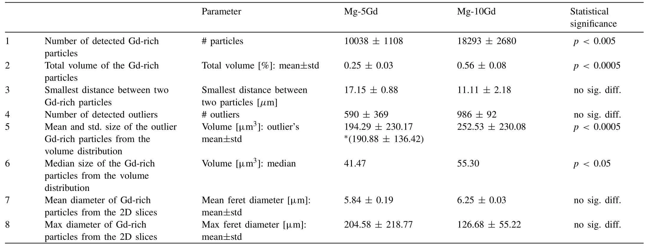
Table 4 Quantitative analysis of the volume,distribution and size of Gd-rich particles in Mg-5Gd and Mg-10Gd screws(SRμCT n=5)in a chosen volume-of-interest.∗Calculation performed after removal of the very high outlier volume 10257 [μm3].

Table 5 Wt.% Gd calculated with EDS as a function of the whole area(surface of the screw and the bulk),a line measurement(yellow line),a point measurement and μXRF-measurements.Reference Fig.11.
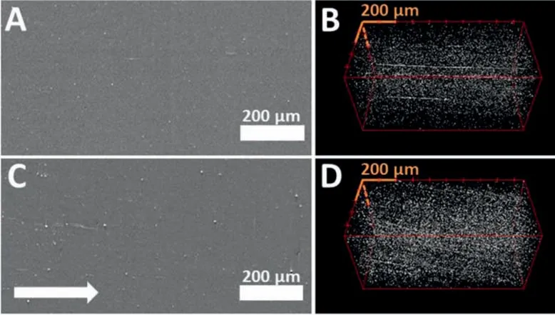
Fig.6.(A,C)2D tomographic slices of Mg-5Gd(A)and Mg-10Gd(C)screws in the longitudinal direction of the screw(arrow:extrusion direction).(B,D)Segmented Gd-rich particles(white dots)in a VOI(480×480×960 μm3)of Mg-5Gd(B)and Mg-10Gd(C),respectively;voxel size=2.4 μm.
TheDRVLvalues of Mg-5Gd degraded in the different media for 28 days show little difference:α-MEM:0.30±0.013 vs.DMEM:0.33±0.03.For Mg-10Gd after 28 days in the same media theDRVLvalues vary more than 50%(α-MEM:0.19±0.01 vs.DMEM:0.34±0.10).
The meanDRVLvalues of experiment(ii)and(iii)(7–56 days immersion time)are plotted again in Fig.9A,with other computed parameters.Both materials start nearly with the sameDR,but Mg-10Gd shows a stronger reduction over time.The correspondingMDDis presented in Fig.9B.The fitted slope indicates that Mg-5Gd has a higherGDRthan Mg-10Gd(Table 7),which agrees with theDRtrend.

Fig.7.(A)SEM image of the surface of an Mg-5Gd screw;(B)BSEM image of Mg-5Gd screw in the bulk.White dots represent either Mg5Gd intermetallic phases or GH2 particles;Yellow line:Line crossing two grains.

Fig.8.Visualization of not corroded and corroded Mg screws.(A)3D volume rendering after segmentation of a Mg-5Gd screw before immersion/degradation.(B)3D volume rendering after segmentation of a Mg-5Gd screw after 56 days in vitro degradation and subsequent removal of the degradation layer.(C)A slice from the middle of the screw after degradation and before the removal of the degradation layer.The green line indicates the border between the preimplantation screw and the background.The red line indicates the border between the degradation layer and the residual i.e.not degraded material.The difference layer is given by the area between the green and the red line.The yellow line indicates the deepest pit(DP)within the depicted slice.
TheCVof thevolume loss,which is the ratio between the2D-mean volume lossand the2D-std volume loss,is presented in Fig.9C and Table 8.It shows that Mg-5Gd starts with a smallerCV,hence a lower variation of the amount ofvolume lossalong the screw and a very small standard variation between the samples in the 1st,2nd weeks compared to Mg-10Gd.It increases for both materials with immersion time,more for Mg-5Gd,which at the last time point is approximately 35,and 25% for Mg-10Gd.
The 3D-PFrepresents the degradation homogeneity of the 3D dataset.In contrast,the 2D-PF,being calculated slicewise,represents the degradation homogeneity of the same dataset statistically.The3D-PFvalues presented in Fig.9D and Table 8 are much higher than the2D-mean PFvalues(presented in Fig.9E and Table 8).There are no recognizable differences or tendencies in the3D-PFbetween both alloys and/or time points.With the exception of the 1st week,Mg-10Gd shows a decreasing2D-mean PFreaching its maximum in the second week and a minimum in the 8th week.By contrast,Mg-5Gd does not show any tendency,but shows overall smaller mean values than Mg-10Gd,except for the 8th week,were they reach equity.TheCVof the2D-PFpresented in Fig.9F shows that there is a tendency of decreasingCVfrom the 1st to the 8th week in case of Mg-10Gd and.Mg-5Gd shows values like Mg-10Gd in the 1st and the 8th week and up to 10% lowerCVs(meaning more homogeneous)values for 2nd,3rd,and 4th weeks.
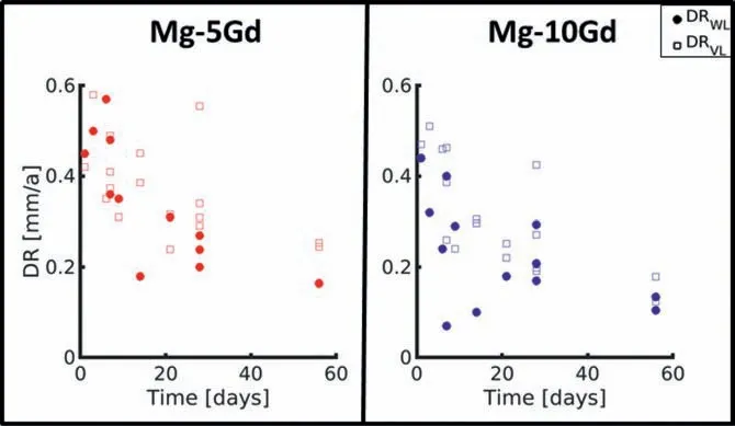
Fig.9.Degradation rates calculated via weight loss(DRWL)and volume loss(DRVL),respectively.
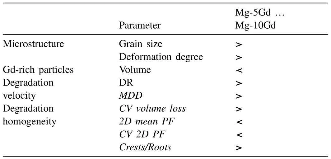
Table 6 Comparison of analyzed parameters for Mg-5Gd and Mg-10Gd screws.
Fig.9G presents the ratio of the degradation between the crests and roots of the threads.
Both materials show crest-to-root ratios higher than 1,indicating faster degradation in crests compared to roots.It is visible that there is a tendency of increasing crest-to-root ratio of the degradation layer for Mg-10Gd from the 1st week to 8th week.Generally,Mg-5Gd shows higher values than Mg-10Gd.Until week 4,Mg-5Gd screws degrade up to 50%stronger at the crests than Mg-10Gd.
Although the overall standard deviations are large,in particular for the degradation parameters,the observed differences between both materials are summarized in Table 5.
4.Discussion
In the following,we will discuss the effect of the microstructure on the different degradation behaviors to highlight the advantages and disadvantages of the alloys for the use as an implant material(assuming a similar behavior to be observedin vivo).
This study supports the tendency of higher extrusion speeds to result in bigger grain sizes as observed in [10];Mg-5Gd with higher extrusion velocity revealed bigger grain sizes in comparison to Mg-10Gd.Additionally,a more homogeneous microstructure of Mg-10Gd samples in comparison to Mg-5Gd was observed.
The investigation of the influence of the machining on the near-surface microstructure of the screws revealed higher and regionally deeper microstructural deformations in coarse grained Mg-5Gd than Mg-10Gd.The latter is in agreement with previous findings of Gawlik [25].
The Mg-5Gd matrix with a coarse grain structure revealed more tensile twins and tensile twin boundaries than the finegrained Mg-10Gd alloys.This result is in agreement with the fact that the growth of the twins is limited by the grain size,hence bigger grains produce bigger twins and consequently,more twin boundaries [58].
Fig.10,Table 10.

Table 7 Number of samples used for in vitro investigation per measurement time point.

Table 8 Degradation rates(DR)[mm/a], α-MEM or DMEM +10%FBS+1% pen/strep,weight loss(WL),volume loss(VL).

Table 9 All data to graphs.

Table 10 μCT parameters.
Furthermore,Mg-5Gd reveals higher kernel average misorientation values than Mg-10Gd,and hence has overall more deformed structures.Recently,intrinsic and extrinsic influences of the alloying elements on the microstructure and the degradation behavior of biodegradable implants has been reviewed by Bahmani et al.[59].There,it has been concluded that in the case of single grains like single crystals or bicrystals,the corrosion rate increases with increasing grain size,while in very fine grains(<50 μm),the corrosion rate decreases by decreasing the grain size.It was previously discussed that the chemical activity at grain boundary regions increases the dissolution rate of fine grained alloys [60,61,62]and that more unstable microstructural features have higher energies,which could accelerate the degradation process.We hypothesize that this process is responsible for the faster degradation speeds observed for Mg-5Gd.This is in contrast to the hypothesis of Gawlik [25]that thicker twinning zones slow down the dissolution rate of the alloy by acting as borders between the grains.

Fig.10.Results of semi static in vitro investigation of Mg-5Gd and Mg-10Gd screw implants over 7–56 days period(experiment(ii)+(iii))from tomography images.(A)Degradation rate,(B)Mean degradation depth with linear regression fits(GDR:Mg-5Gd=0.21 mm/a;Mg-10Gd=0.11 mm/a),(C)Coefficient of variation of the volume loss over the transversal slices of the 3D implant,(D)2D mean pitting factor,calculated for each slice with its MDD,(E)Coefficient of variation from(D),(F)Ratio of the degradation layers at the crests and at the roots of the samples.
Apart from having an influence on the degradation rate,the deformation has also impacted the mechanical properties of the material.Extension twinning occurs under tensile stress along the crystallographic c-axis,which results in a sudden re-orientation of parent grains by approximately 86.3°[63,64].When the tension twinning dominated deformation exhausts,a fast strain hardening is happening,which later leads to an early fracture [65].From this,we conclude that the weaker texture of Mg-10Gd could be more beneficial for the deformation accommodation by the dislocation slip and more homogeneous deformation,thus lower risk for an early fracture can be expected for the Mg-10Gd alloys.
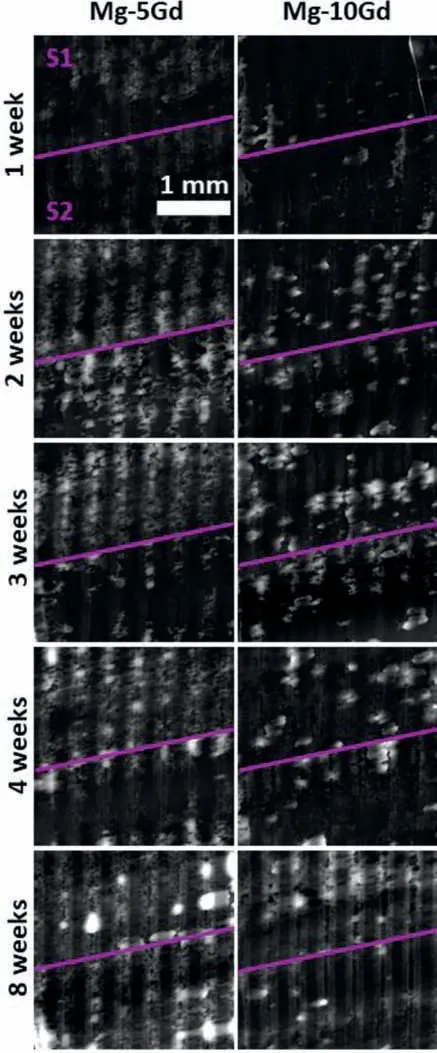
Fig.11.2D degradation layers of the investigated Mg-5Gd and Mg-10Gd from 7 to 56 days corroded screws.S1/S2 indicating Sample1/Sample2;Scale bar same for all images=1 mm;grey levels:brighter=more corroded,darker=less corroded.Mg-10Gd,8 weeks,S2(right bottom):yellow area=Acrest,green area=Aroot.
In addition to the deformations,the presence of metallic particles in the alloys may have an influence on the degradation behavior.The bright particles observed in the 3D volume are assumed to be agglomerations of GdH2particles,which is in agreement with the literature [10,66].Under the assumption that these particles act as sites for galvanic corrosion,the smaller the particles and the more homogeneously distributed,the more homogeneous the degradation mechanism should be.Additionally,the more particles present in the alloy the faster the degradation rate should be.Based on the observed degradation behavior it appears that the presence of these particles is negligible.
Based on the computed parameters,no clear conclusion can be drawn in terms of the homogeneity of both materials’degradation.It can speculate on three different observed ways driving the implant’s non-uniform degradation:
1.Localized non-uniform degradation in terms of the degradation depth differences on the screw’s crest and root areas.This observation is made for both alloys,although in the first four weeks the effect is more visible in Mg-5Gd than in Mg-10Gd.
2.Localized non-uniform degradation in terms of the pitting corrosion described with the 3D and 2D mean PF values.Similar to[67],the higher values of 2D mean pitting factor in the Mg-10Gd samples are caused by a lower average degradation depth and rather high pits.This effect is even more visible in the parameter 3D PF.Instead of averaging the deepest pits along the screw’s cross sectional slices only the deepest pit is considered in the calculation.The high variation of the 3D PF among all investigated samples indicates the sensitivity of this parameter.It also suggests the non-homogeneous degradation behavior of the samples among same alloy and/or probably the less significance of the 3D PF parameter.The deepest pits are approximately 632.5 μm in Mg-5Gd and 379.5 μm in Mg-10Gd and can be more than twice as deep as the screw thread.In general,the decrease of the pitting factor values during longer degradation periods can be due to several reasons:(i)several small pits could merge;(ii)inhomogeneities,like GdH2particles,could fall out of the pits;(iii)small pH differences between the surface and the deep pits,leading to slower degradation rates at the deeper pits than at the surface;(iv)larger screw surface area at the top of the pit than at the bottom of the pit,hence less surface energy and slower degradation rates at the depths of the pits than at the tops.
3.Non-localized non-uniform degradation increasing during the degradation time period.The latter two points of the localized non-uniform degradation(iii and iv)could also be a reason for the degradation rate differences at the roots and the crests of the screws.
In this study,a greater decrease of degradation rate with the immersion duration of Mg-10Gd screws in comparison to Mg-5Gd could be detected.Kubásek and Vojtˇech [9]dis-cussed that the Gd3+cations substitute Mg2+cations in the degradation layer,hence slowing down the degradation process.One of the reasons that Mg-5Gd screws degraded faster than Mg-10Gd could be the amount of Gd dissolved in the Mg-matrix.This difference becomes stronger for longer immersion times,consistent with Harmuth et al.[10]who did not find any significant correlation between the degradation rate and the alloy composition in a short time of 7 days corrosion tests of Mg-Gd alloys with 2,5 and 10 wt.% Gd content.
The known fast degradation rate of Mg bone implants has also recently been mentioned by Yang et al.[24].Mg-10Gd has been testedin vivoandin vitroby Marco et al.[68]over a short time period of up to 7 days.Myrissa et al.[66]and Galli et al.[69]tested Mg-10Gdin vivoover a time period of 12 weeks in a transcortical and monocortical rat femur model,respectively.Myrissa et al.[66]reported an initial low degradation rate without gas bubbles,but afterwards a very fast degradation rate with a high amount of gas bubbles visible.After 12 weeks of implantation nearly a complete dissolution of the implant in the bone was observed.This would not be acceptable for a fracture fixing implant,since it should provide structural stability at least for 12 weeks [66,70].On the other hand Galli [69]concluded that Mg-10Gd showed a degradation behavior appropriate for bone formation and stable degradation layer.The different outcomes of experiments may be arising from different microstructures,differences in the production and manufacturing of the implant,place of implantation and different imaging modalities [69].With respect to the degradation velocity,both investigated materials reveal a degradation rate appropriate for orthopedic implants [3].It was shown that degradation rates lower 0.5 and higher than 0.2 mm/a would match the bone healing rates [71].According to Rahim et al.[3]the bone healing time can range from a month to six months in humans.By considering the calculated global degradation ratevolumelossof 0.25 mm/a for Mg-5Gd after 56 days of degradation,the mean degradation depth of Mg-5Gd after 6 months is 115 μm.Performing the same mean degradation rate calculation for 6 months for Mg-10Gd one obtains a mean degradation rate of 69 μm(with global degradation ratevolumeloss=0.15 mm/a).Therefore,for the given implant geometry,Mg-5Gd would remain in the body for 4.3 years and Mg-10Gd for 8.1 years,before dissolving completely(assuming mean degradation rate=radiusimplant=0.9 mm).However,as we have shown that both materials degrade inhomogeneously,and given the sizes of the deepest pits,it is possible that the dissolution will occur fasterin vivo.Based on this inhomogeneity,future tests must also consider the change in mechanical stabilities of the implants over time.
Overall,in contrast to weight loss measurements,SRμCT measurements allow to assess the volume loss and enable a description of the degradation homogeneity qualitatively and quantitatively.Depending on the degradation period and image resolution volume loss measurements can give more precise results than the weight loss measurements of the degradation rate.
5.Conclusions
In this study two Mg-xGd alloys(Mg-5 wt.% Gd and Mg-10 wt.% Gd)were investigated non-destructively in 3D in terms of theirin vitrodegradation velocity and homogeneity for short and long immersion times.Digital 3D analysis yields the volume loss measurements and allows to access further parameters describing the homogeneity of the degradation qualitatively and quantitatively.In particular,the pitting factor calculations,enable the quantitative analysis of the degradation homogeneity and are thus preferred over sole weight loss measurements.
Our analysis suggests that Mg-10Gd has an overall lower degradation rate,more homogeneous microstructure and a weaker texture than Mg-5Gd.Futurein vivotests need to be carried out to verify the degradation behaviorin vivoand extrapolate the materials’ suitability for implant materials.
Acknowledgements
This research was carried out within the SynchroLoad project(BMBF project number 05K16CGA)which is funded by the Röntgen-Ångström Cluster(RÅC),a bilateral research collaboration of the Swedish government and the German Federal Ministry of Education and Research(BMBF).We acknowledge also the project MgBone(BMBF project number 05K16CGB).We acknowledge DESY(Hamburg,Germany),a member of the Helmholtz Association HGF,for the provision of experimental facilities.We acknowledge provision of beamtime at beamline P05 at PETRA III at DESY related to the proposal I-20160104 and we would like to thank Felix Beckmann,Jörg Hammel and Fabian Wilde for assistance in using P05.We acknowledge the KIT light source for provision of instruments at their beamlines and we would like to thank the Institute for Beam Physics and Technology(IBPT)for the operation of the storage ring,the Karlsruhe Research Accelerator(KARA).We further thank Monika Luczak and Eshwara Nidadavolu for the help in performance of the immersion tests.This research was supported in part through the Maxwell computational resources operated at Deutsches Elektronen-Synchrotron DESY,Hamburg,Germany.We also acknowledge Sarkis Gavras for proofreading the article.
Appendix
In order to reveal best image quality some of scan parameters were varied(Table 9).
 Journal of Magnesium and Alloys2021年6期
- Journal of Magnesium and Alloys的其它文章
- Rapid-developing Mg-based biodegradable materials:The editorial of the special issue on Mg-based functional materials -biomaterials section
- Magnesium-Based Materials for Energy Conversion and Storage
- A special editor’s issue on Mg-based functional materials:Design and development
- A combination strategy of functionalized polymer coating with Ta ion implantation for multifunctional and biodegradable vascular stents
- Enhanced hydrogen generation from hydrolysis of MgLi doped with expanded graphite
- In vitro corrosion-fatigue behavior of biodegradable Mg/HA composite in simulated body fluid
