
Broadband and efficient second harmonic generation in LiNbO3-LiTaO3 composite ridge waveguides at telecom-band
2021-01-21 02:07:36XinTongZhang张欣桐
Chinese Physics B 2021年1期
Xin-Tong Zhang(张欣桐)
Department of Optics and Optical Engineering,University of Science and Technology of China,Hefei 230026,China
Keywords: second harmonic generation,lithium niobate ridge waveguide,dispersion manipulation
1. Introduction
Second-order nonlinearity χ(2)is crucial for nonlinear optical parametric processes, such as second harmonic generation (SHG), sum and difference-frequency generation(SFG/DFG). These dynamical processes are most prominent approaches to achieve modern nonlinear optical applications, including optical parametric oscillators,[1]wavelength division multiplexing,[2]super-continuum generation[3]and quantum information processing.[4]The quasi-phase-matched(QPM) wavelength conversion engineering based on periodically poled lithium niobate(PPLN)waveguides is widely employed for these applications, owing to their transparency to signal format and ultrafast interaction speed. Lithium niobate(LiNbO3) crystal is a suitable χ(2)material choice for wavelength conversion because of its large second order nonlinear coefficients (d33= 25 pm/V), wide transparency range from UV to mid-IR and high refractive index. Due to these remarkable features, LiNbO3(LN) crystal becomes an efficient and prevail routine in a variety of optical and photonic applications.
Efficient wavelength conversion is essential for a range of optical applications, such as quantum storage[5]and optical frequency comb.[6]Since the nonlinear frequency conversion efficiency is related to the intensity of optical waves inside devices, LiNbO3waveguides with tight optical confinement were widely used to enhance the nonlinear interaction strength. Recently, some outstanding works based on lithium niobate thin films have been demonstrated. Peak normalized SHG efficiency of 160%W-1·cm-2has been achieved in PPLN waveguides on silicon nitride thin-film LN platforms.[7]Ultra-high wavelength conversion efficiency of 2600%W-1·cm-2has been realized by Wang using PPLNOI waveguides.[8]Luo et al. experimentally demonstrated a significant SHG-spectrum-tuning slope of 0.84 nm/K with a nonlinear conversion efficiency of 4.7%W-1·cm-2in a lithium niobate nano-photonic waveguide.[9]It is indicated that lithium niobate waveguides are a promising candidate for future integrated wavelength conversion systems.
Meanwhile, broad frequency conversion bandwidth is also highly desirable in many applications such as ultrafast optical signal processing, frequency tunable lasers, and optical telecommunications.[10–12]However, due to the groupvelocity mismatching between interaction waves, acceptance bandwidth of highly efficient PPLN frequency conversion process is generally narrow, typically ~50 GHz(~0.4 nm),[13]which limits its applications in ultra-shortpulse compression,[14]frequency tunable lasers[15]and optical telecommunications.[16]Several approaches have been demonstrated to broaden the acceptance bandwidth of SHG,including aperiodic domain inverted gratings[17,18]and chirping periodically poled crystals.[19,20]However, the performance of these method is usually limited by the noticeable ripples response,fabrication difficulties,additional production costs and efficiency fluctuations.[21]
Highly efficient and simultaneously broadband second harmonic generation is of vital importance for optical applications. Ultra-broadband and efficient SHG has been realized through dispersion engineering at 2 μm wavelength,[22]whereas the specifically designed waveguide with low dispersion at 2 μm may not be applicable for dispersion properties at telecom-band. In this study, we theoretically demonstrate a broadband and efficient second harmonic generator at telecom-band,which is made of a LiNbO3ridge waveguide on a LiTaO3(LT) substrate. Through achieving simultaneously group velocity and quasi phase matching,the acceptance SHG bandwidth of >2.5 THz(~20 nm)was achieved in a 10-mmlong ridge-waveguide sample,with a conversion efficiency of>25%W-1·cm-2.
2. Designed waveguide structure
Figure 1 gives a schematic view showing the overall layout of the designed waveguide structure. The LiNbO3film layer was bonded on the top of the LiTaO3substrate, both the LN film and the LT substrate were diced to form a ridge with depth of 10 μm. The LiNbO3core thickness was modulated from 2.25 μm to 3 μm for different waveguide configurations. Optical wave was restricted in the top LN layer because of the higher refractive index of LN. LiTaO3was used as the substrate material in our device because the refractive index difference between LiNbO3(ne=2.13, no=2.21 at 1.55 μm) and LiTaO3(ne=2.12, no=2.11 at 1.55 μm)was quite small, which effectively reduced the waveguide dispersion and contributed to a large SHG acceptance bandwidth, at telecom-band. Additionally, as the thermal expansion coefficient of LiTaO3(α = 14×10-6◦C-1)and LiNbO3(α = 16×10-6◦C-1) were similar, the nonlinear performance degradation and structural instability induced by thermal stress between two layers may be prevented by using the LiTaO3substrate. The solid-source MOCVD[23]and direct hetero bonding(D-HEB)[24]method were proved to be capable of fabricating a high quality single-crystal LiNbO3film on the LiTaO3substrate for waveguide applications. The fabrication of low-loss ridged LiNbO3waveguides with ultra-smooth sidewalls has been demonstrated using the optical-grade dicing method.[25–27]The above experiments proved that our device was experimentally accessible.
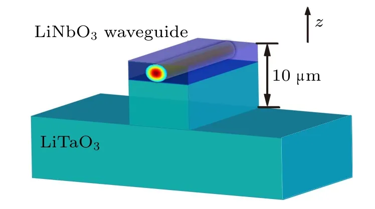
Fig. 1. Schematic diagram of the Z-cut LiNbO3 ridge waveguide and the LiTaO3 substrate.
3. SHG with birefringent phase matching
Firstly, second harmonic generation (SHG) properties,such as efficiency and acceptance bandwidth, in our device were investigated under birefringent phase matching (BPM)condition. In our simulations,the sample length was assumed to be 10 mm. The refractive index and dispersion information used in the simulation were obtained numerically from the Sellmeier equation published.[28,29]The initial pump wavelength was fixed at 1.55 μm. The temperature was tuned in a reasonable range from 20◦C to 220◦C.The designed width of the ridge waveguide was adjusted from 2 μm to 4 μm,while the LiNbO3core thickness varied from 2.25 μm to 3 μm(see Table 1). The optical guiding modes and effective indices were calculated using the FDE Eigen-mode solver simulations(Mode Solution, Lumerical Corp). Birefringent phase matching between orthogonal polarizations (o+o →e, type-I modal interaction) was employed here. Although the nonlinear coefficient(d31= 4.3 pm/V)is not comparable to that of type-0(e+e →e,d33= 25 pm/V)interactions,the wavevector mismatch varies slowly with fundamental wavelengths under type-I interaction,which provides a broader SHG output spectrum in contrast to traditional type-0 interaction.[30,31]As shown in Fig.2,the type-I birefringent phase matching condition was achieved in four waveguides successfully within the temperature range tunable.
No high-order modes satisfying phase matching conditions were found within the preset waveguide geometry. The fundamental transverse electric mode(TE0 for no)was phase matched with the fundamental transverse magnetic mode(TM0 for ne). The normalized conversion efficiency was calculated using the following equation:
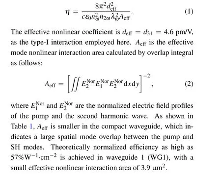

Table 1. Details of waveguide 1 to waveguide 4.
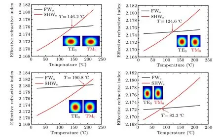
Fig.2. Effective indices as a function of temperature under BPM conditions at the wavelength of 1550 nm in(a)WG1,(b)WG2,(c)WG3,(d)WG4(for specific parameters see Table 1). Inset shows the modal profiles of the pump(TE0)and SH(TM0)waves.
WG1(geometry size of upper LN layer: width=3,thickness=2) was utilized as an example in the following simulations. The SHG acceptance bandwidth of WG1 was investigated by calculating the normalized conversion efficiency.The output SHG power was proportional to phase mismatch factor given by
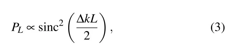
where Δk was phase mismatch factor, and L was the sample length. Figure 3 illustrates the normalized SHG spectrum in WG1. A dual SHG wavelength peak was achieved. The calculated phase mismatch factor as a function of pump wavelengths was also presented. The phase match condition was satisfied (Δk = 0) under both 1520 nm and 1558 nm, at the temperature of 146.2◦C. The full width at half maximum(FWHM) of two SHG peaks were both 9 nm with the sample length of 10 mm.
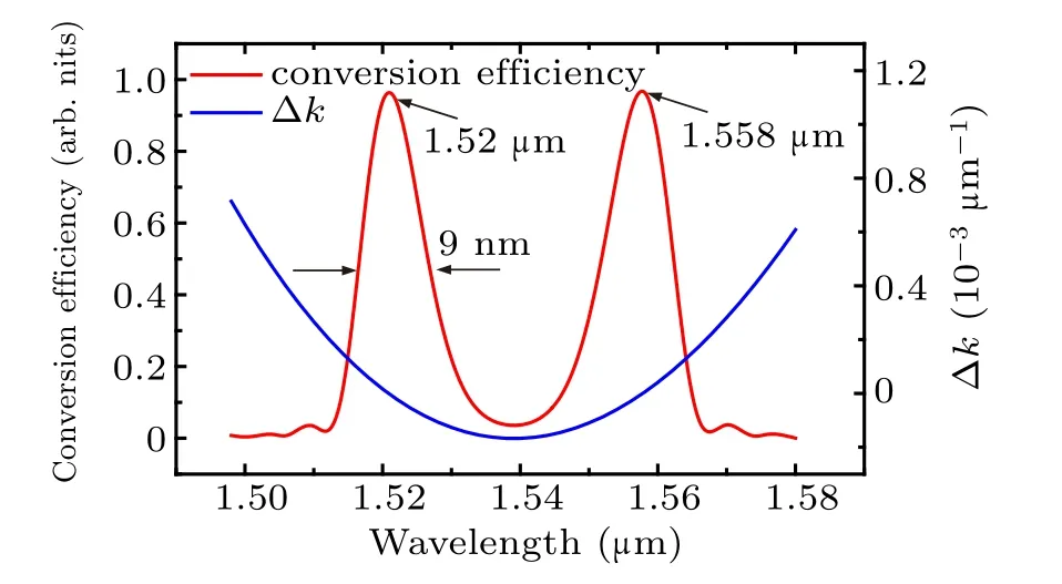
Fig.3. SHG acceptance spectrum and mismatch factor in waveguide 1 at 146.2 ◦C.
The simulation results verify that the designed device shows well performance in both efficiency and spectrum responses. In WG1, the SHG efficiency is as high as 57%W-1·cm-2, with a broad spectrum bandwidth of 9 nm(the length of waveguide is 10 mm). The bandwidth performance is promoted compared with former high efficient SHG experiments.[7,9]It is attributed to the fact that the mismatch factor varies gently versus wavelengths in our designed device,and this character results in a wide spectrum phase matching.Additionally, in order to further broaden the SHG response bandwidth, group velocity matching is introduced in the following simulations.
4. Group velocity matching with QPM
Group-velocity mismatching results in a narrow nonlinear interaction spectrum bandwidth, because during interaction,the pump wave and SH wave walk away from each other due to the mismatch of group velocity.[32]Group-velocity matching(GVM) usually cannot be satisfied under birefringent phase matching regime, as shown in Fig. 3, the phase matching wavelengths are 1.52 μm and 1.558 μm,but the group velocity matching was satisfied under the wavelength of 1.54 μm(dΔk/dω = 0). To eliminate walk-off effect and achieve a broader SHG acceptance band, quasi-phase match (QPM)was implemented to compensate for the phase mismatch under group velocity matching condition.[13,31]The mismatch factor is defined as ΔkQPM= Δk-K, where K is the QPM grating vector, given by K = 2π/Λ, Λ = λ/2(n2ω-nω) is the period of inverted domain. The expansion term of the phase mismatch is expressed as
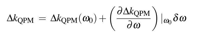


Fig. 4. (a) Acceptance bandwidth of the PPLN sample (waveguide 1)under 25 ◦C; (b) group-velocity mismatch and phase mismatch factor of WG1 as a function of wavelength.
The normalized QPM SHG conversion efficiency versus wavelength in WG1 with group velocity matching is illustrated in Fig. 4(a). The simulation was carried out at the room temperature(25◦C).The zero-group-velocity dispersion wavelength is 1.49 μm, where the wave-vector mismatching takes the extremum [see Fig. 4(b)]. The QPM polarization period is calculated to be 133 μm. It should be noted that the nonlinear coefficient is modulated by ±deffin the QPM scheme, thus the effective nonlinear susceptibility in Eq. (1)is replaced by dQPM=2d31/π = 3 pm/V.The simulation results indicate that our device achieves a large SHG bandwidth of 24 nm (~3 THz) while maintains a high conversion efficiency of 25%W-1·cm-2, which is beneficial for wavelength conversion applications in integrated optics platforms. Meanwhile, the effects of the sample length on the SHG efficiency and the acceptance bandwidth are also investigated, as listed in Table 2.
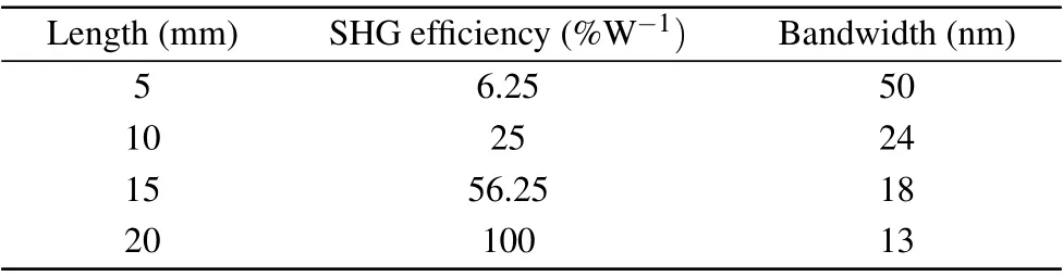
Table 2. SHG efficiency and bandwidth related to sample length.
There is a trade-off between efficiency and bandwidth,because efficiency grows with the waveguide length as L2,[33]while the bandwidth narrows because different wavelengths can accumulate different phase mismatchs (ΔkL) as L grows,according to Eq.(3). In fact, the bandwidth is decided inherently by dispersion properties of Δk,rather than the length L.Essentially,we design the waveguide to reduce the dispersion effect of Δk and to achieve a broad bandwidth, so the sample length is fixed at 10 mm in our work.
The polarization inverted voltage and electric resistance of LiNbO3decrease dramatically with magnesium oxide(MgO)doped,which is beneficial for the nonlinear characteristics and commercial applications of LiNbO3. Thus,simulations were performed using the MgO-doped LiNbO3sample.The refractive index and dispersion are described by the Sellmeier equation of MgO-doped LN.[34]The calculated GVM wavelength of MgO-doped WG1 is 1.455 μm, with a conversion efficiency of 26.8%W-1·cm-2at room temperature.The calculated bandwidth is 23 nm with a grating period of 65 μm. The GVM wavelength is altered to communication wavelength of 1.548 μm as temperature increases to 61◦C,as illustrated by Fig. 5(a). The 3-dB acceptance bandwidth is broadened to 26 nm, at the cost of reduction in efficiency(23.8%W-1·cm-2). The calculated inverted domain period is 174 μm. It could be concluded that MgO-doping has little impact on SHG output features. However,it is worth noting that the crystal properties,such as non-linearity and electro-optical characteristics,will be largely promoted with MgO-doping in practical applications.
In order to investigate the SHG properties in waveguides with different geometrical parameters,the size of ridge waveguide is enlarged on the basis of WG1 (LN waveguide size:width=3 μm, thickness=2 μm). As depicted in Fig. 5(b)(green line), with the thickness of LiNbO3core increasing from 2 μm to 3 μm, the GVM wavelength is altered to 1.471 μm,at room temperature. The central wavelength conversion efficiency is 19%W-1·cm-2with acceptance bandwidth (ABW) of 25 nm. Next, the LN waveguide cross section area is further enlarged to 4×4 μm2, the GVM wavelength becomes 1.506 μm and the acceptance bandwidth is broadened to 27 nm while the conversion efficiency decreases to 10.6%W-1·cm-2. With temperature altered to 40◦C (red curve in Fig. 5(b)), the GVM wavelength of the 4×4 μm2cross-section waveguide is shifted to 1.545 μm. The acceptance bandwidth is as large as 28.4 nm with a grating period of 38 μm,while the conversion efficiency further decreases to 10%W-1·cm-2. Furthermore, as the device temperature increases, the GVM wavelength shifts with a tuning slope of 3.08 nm/◦C, as shown in Fig. 5(c). Under 85◦C, the GVM wavelength is 1.69 μm, the acceptance bandwidth increases to 35 nm,due to the decrease in material dispersion at longer wavelengths.
It is concluded that as the waveguide geometry grows larger, the SHG efficiency decreases, but the bandwidth is broadened. Once the QPM and GVM are both satisfied(Δk(ω0) = 0,Δk′(ω0) = 0),the mismatch and bandwidth are dominated by higher(second)order dispersion
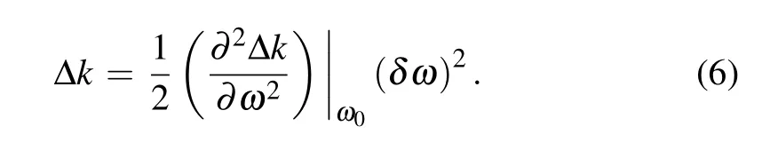
Here Δk′′is induced by group velocity dispersion mismatch between fundamental wave and second harmonic wave. The second order mismatch Δk′′at GVM wavelength is calculated as listed in Table 3. Δk′′of the bulk material is also calculated for comparison.
The dispersion in waveguide devices is comprised of material dispersion and waveguide dispersion. Table 2 indicates that as the waveguide becomes more compact, the tight optical confinement introduces a stronger waveguide dispersion,which results in a narrower SHG bandwidth in our device.
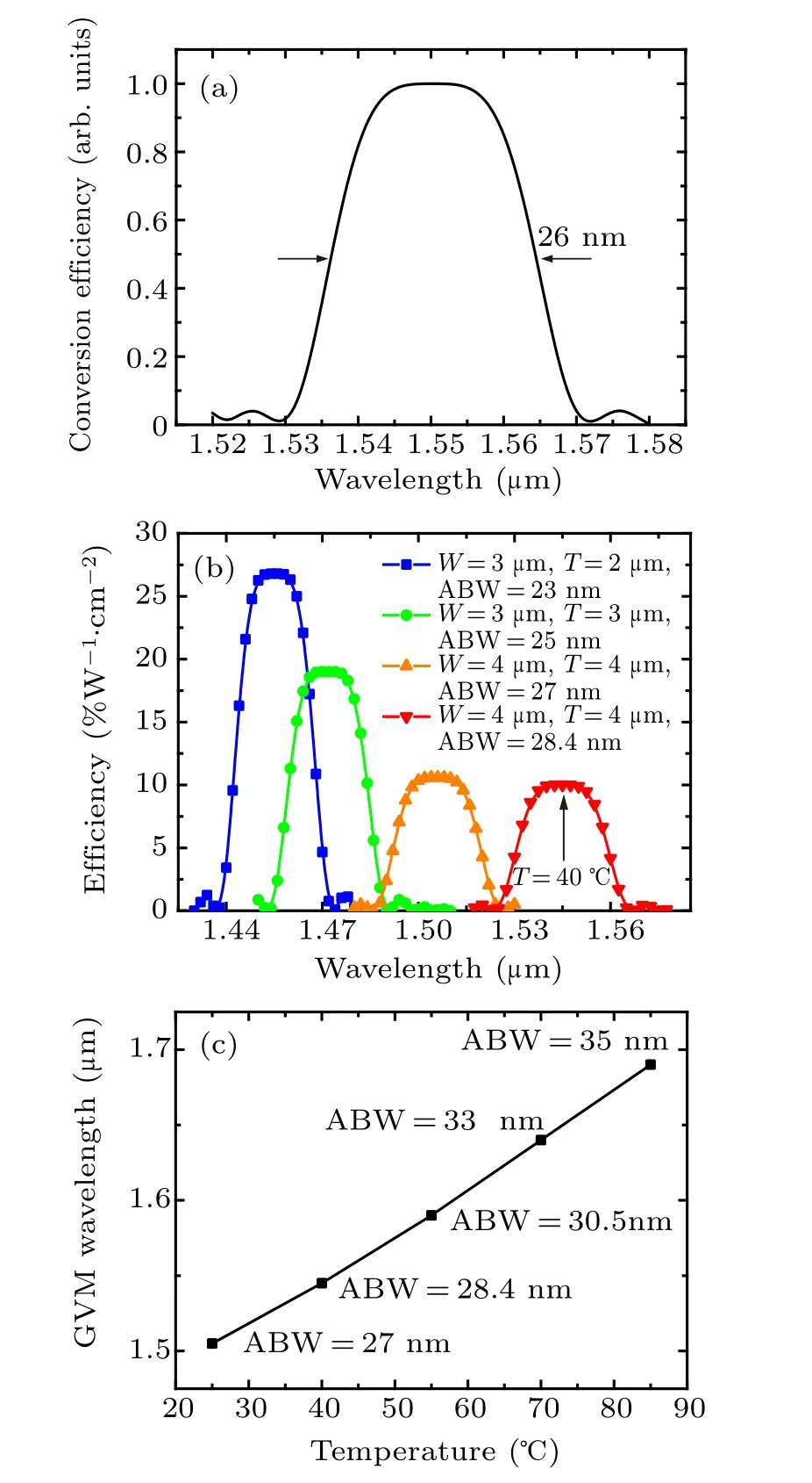
Fig. 5. (a) Normalized SHG efficiency versus wavelengths under 61 ◦C in MgO doped WG1;(b)GVM wavelength evolution and SHG acceptance bandwidth (ABW) of different waveguides (W: width, T: thickness); (c)GVM wavelength versus temperature in waveguide with 4×4 μm2 cross section.
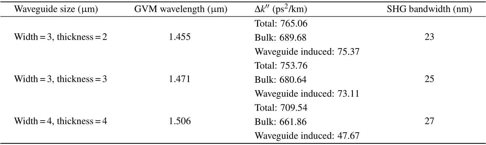
Table 3. Dispersion properties of different waveguides under GVM conditions.
Simulations were also performed with type-0 QPM configuration (e+e →e) to characterize the highest conversion efficiency by utilizing the largest non-linearity component:(dQPM= 2d33/π = 16 pm/V, d33= 25 pm/V). The GVM wavelength for type-0 QPM is above 2.5 μm, far away from waveband of 1550 nm. Here, the pump wavelength is set to be 1550 nm, with the temperature of 25◦C. The simulation results are depicted in Fig. 6. Owing to the low index difference between LiNbO3(ne= 2.13 at 1.55 μm)waveguide and the LiTaO3(ne= 2.12 at 1.55 μm) substrate layer, the fundamental TM mode can only be supported in the waveguide with large LiNbO3core sizes(4×4 μm2). The conversion efficiency as high as 303%W-1·cm-2is achieved theoretically,with a grating period of 15.58 μm.The SHG acceptance bandwidth is only 0.41 nm, about 50 times lower than the type-I QPM interaction.
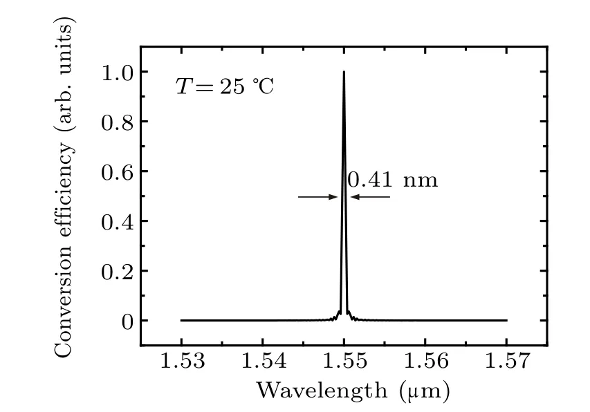
Fig. 6. SHG spectrum of type-0 interaction under wavelength of 1550 nm at 25 ◦C.
5. Conclusion
We have theoretically demonstrated a new type of optical waveguide composed of LiNbO3and LiTaO3materials that can be used for broadband, high-conversion-efficiency SHG at telecommunication band. By optimizing simultaneously the group-velocity and quasi-phase matching conditions in this ridge waveguide, the 3-dB acceptance bandwidth of pump wavelength can be broadened to 24 nm in a 10-mmlong sample, and the conversion efficiency can be as high as 25%W-1·cm-2. We also demonstrate that several parameters of the SHG process in this waveguide, including the spectral bandwidth,conversion efficiency and central wavelength,can be tuned by adjusting the size and temperature of the waveguide. Since the LiNbO3crystal and the LiTaO3substrate have similar thermal-expansion coefficients,the waveguide structure demonstrated here has largely reduced built-in stress as the device temperature varies,allowing stable nonlinearity performance and good structure robustness.
Acknowledgment
X.T.Zhang appreciates Professor Meng Pang(Shanghai Institute of Optics and Fine Mechanics, Chinese Academy of Sciences)for his helpful advice.

- Chinese Physics B的其它文章
- Numerical simulation on ionic wind in circular channels*
- Interaction properties of solitons for a couple of nonlinear evolution equations
- Enhancement of multiatom non-classical correlations and quantum state transfer in atom–cavity–fiber system*
- Protein–protein docking with interface residue restraints*
- Effect of interaction between loop bases and ions on stability of G-quadruplex DNA*
- Retrieval of multiple scattering contrast from x-ray analyzer-based imaging*