Random-injection-based two-channel chaos with enhanced bandwidth and suppressed time-delay signature by mutually coupled lasers: Proposal and numerical analysis*
Shi-Rong Xu(许世蓉), Xin-Hong Jia(贾新鸿), Hui-Liang Ma(马辉亮),Jia-Bing Lin(林佳兵), Wen-Yan Liang(梁文燕), and Yu-Lian Yang(杨玉莲)
College of Physics and Electronic Engineering,Sichuan Normal University,Chengdu 610101,China
Keywords: random distributed feedback-based optical injection, two-channel chaos lasing, bandwidth enhancement and time-delay signature suppression,physical random number generation
1. Introduction
In recent years, chaotic light produced by semiconductor lasers (SL) has been widely studied. Chaotic signal is of great significance for many applications including secure communication,[1–8]chaos-based lidars,[9]optical time domain reflectometries(OTDRs),[10,11]high-speed physical random number generators (PRNGs),[12–22]etc. The nonlinear dynamics of SLs can also be used for all-optical and high-speed neuromorphic calculations with good energy efficiencies.[23]SLs exhibit nonlinear dynamics under external disturbances such as optical feedback,[12,24]optical injection[25,26]and optoelectronic feedback.[27,28]Among them, optical feedback is one of the simplest schemes. However, there is an obvious disadvantage that the chaotic light has clear time-delay signature (TDS) due to the existence of external fixed cavity mode. TDS can be easily identified by an autocorrelation function(ACF),which is potentially harmful to the security of chaos-based communication. Therefore, the identification or hiding of chaos TDS has become a hot topic. The reported suppression methods include delayed self-interference,[29]inserting a phase modulator(PM)driven by high-speed pseudo random bit sequence (PRBS),[30]selfphase modulation optical feedback(SPMOF)combined with a microsphere resonator(MR),[31]and various feedback configurations such as double feedback,[32]filtered optical feedback(FOF),[33]detuned fiber Bragg grating (FBG),[34,35]chirped FBG,[36]and random FBG (RFBG) feedback.[37]However,these feedback schemes for TDS suppression are still limited in bandwidth (BW) due to the use of a single SL, which results in the lower transmission capacity of encrypted data and lower generation rate of PRNG. In order to improve the BW of chaotic light, two types of optical injection, including unidirectionally coupled systems[38–40]and mutually coupled systems,[41–47]have been proposed.
Recently, an unidirectional coupled SL using random Rayleigh scattering feedback over a long fiber and continuous wave(CW)injection has been proposed to generate wideband chaos with suppressed TDS. A chaos output that extends to 13.6 GHz within 3 dB has been achieved.[48]A similar but more compact method combining RFBG feedback and CW optical injection was also demonstrated to obtain flatter spectrum over ~7.53 GHz.[49]It has been proved that random lasing can considerably expand the ranges of parameters for achieving good TDS cancellation compared with single-mirror feedback.[37]Compared with detuning FBG-based TDS suppression that is based on dispersion-induced group delay at the lobe of reflection spectrum,[34,35]using RFBG is more robust and stable,since TDS could be removed without any frequency detuning of the fiber random grating.[37,49]
However, all of the reported TDS suppression by random lasing only supports a single-channel chaos output due to CW injection[48,49]or without injection.[37]The feasibility and study of random lasing-based TDS suppression by two mutually coupled SLs(MCSLs)have not yet been reported. In this paper,a system combining RFBG-based optical injection and MCSLs is designed to simultaneously generate two-channel chaos outputs with both enhanced BW and suppressed TDS.The influences of injected current,coupling intensity and frequency detuning on TDS and BW are investigated in detail.We also numerically analyze the feasibility of simultaneously generating two-channel high-speed physical random number at 200 Gbits/s (for each channel) by the proposed configuration, as a result of high-quality chaos with >20 GHz bandwidth and perfect TDS suppression.
2. Theoretical model
Figure 1 describes the schematic diagram of the proposed MCSLs with random distributed optical injection. In path 1,the light from SL1 firstly passes through a circulator (CIR1),and enters the RFBG1 through CIR2. Then it is reflected by each scattering center with random distribution. After CIR2,it is amplified by a semiconductor optical amplifier (SOA1)and weakened by a variable optical attenuator (VOA1) before being injected into SL2 through CIR3. Path 2 is similar to path 1. These two SLs are subjected to different random optical injections by RFBG1 and RFBG2, which can be divided into M sections with equal length of L/M (L is the length of RFBG). Note that RFBG can be manufactured by femtosecond laser direct writing.[50]In order to simulate the role of random distributed injections on the TDS suppression and chaos BW,considering the computational efficiency,10-cm-long fiber random gratings are divided into M =300 scattering centers.[37]Here,the effective power reflectivity of each scattering subsection for RFBGn (n=1, 2) is denoted by Rnmi(i=1,2,...,M). For simplification, the same Rnmiis assumed. Since the reflectivity of each scattering center is very low, multiple reflections can be reasonably ignored[37](Rnmi=1×10-4is used in our simulation). The uniform distribution is selected for the location of scattering centers.[37]
The nonlinear dynamics of the proposed MCSLs with random optical injection are governed by the following Lang–Kobayashi rate equations[37,43,51–54]
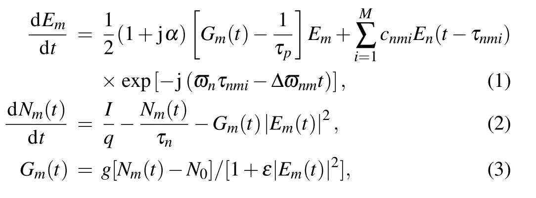
where subscript m,n=1,2(m/=n)stands for SLm and SLn.The second term in Eq.(1)denotes the role of random injection for all of the scattering points. Emand Gmare the optical field and differential gain of SLm,respectively,Nmis the carrier number of SLm,N0is the carrier number at transparency,τpis the photon lifetime, τnis the carrier lifetime, ε is the gain compression coefficient, I is the injection current, α is the linewidth enhancement factor,g is the differential gain coefficient, q is the electric charge, Δωnm=2πΔfnm. Here frequency detuning is defined as Δ fnm= fn- fm. In our simulation, the frequency of SL1 (f1) is fixed, the adjustment of frequency detuning can be realized by changing the frequency of SL2 (f2). To simplify the analysis, the same basic parameters(N0, α, τn, τp, g, ε,and I)are used for SL1 and SL2 in Eqs.(1)–(3).

Fig.1. Schematic diagram of the proposed MCSLs with random distributed optical injection. SL:semiconductor laser; RFBG:random fiber Bragg grating;CIR:circulator;SOA:semiconductor optical amplifier;VOA:variable optical attenuator.
In Eq. (1), coupling strength of each scattering center from SLn to SLm is denoted by cnmi[51–54]

where G is gain of amplifier and L is optical loss of path 1 or path 2 except for RFBG1 or RFBG2, τinis the roundtrip time in laser cavity, R0is the power reflectivity of end-facet for laser cavity(the same values of τinand R0are assumed for SL1 and SL2). As shown in Fig.1,the amplifiers and attenuators can be used to adjust the coupling strength. We assume that c12i=c21iin simulation for simplicity.
In addition, τnmi(i=1,2,...M) in Eq. (1) are the coupling delays for each scattering center, calculated by τnmi=(L1+L2)/(c/ng,fiber)+2znmi/(c/ng,RFBG)(see Fig.1). Here,L1is the distance between SL1 cavity and the starting location of scattering points,L2is the distance between SL2 cavity and the starting location of scattering points,znmi(in the range of [0, L]) is the coordinates of scattering points of RFBGn(n=1,2),c is the light velocity in vacuum,ng,fiberand ng,RFBGrepresent the group refractive index of fiber link and RFBG,respectively. For simplicity, the same L1+L2is assumed for SL1 to SL2 and SL2 to SL1. Note that different realizations for the distribution of scattering centers are utilized for RFBG1 and RFBG2.
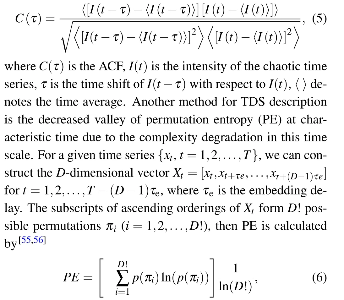
TDS can be characterized by the subpeak of ACF of chaos intensity output,defined as
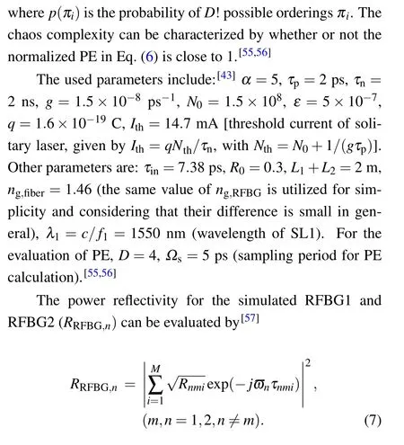
Figures 2(a)and 2(b)show the power reflection spectrum of the used RFBG1 and RFBG2 for simulation from Eq. (7).Multiple interference patterns resulting from the backscattering light from RFBG can be observed. The reflectivity variation for various wavelengths is attributed to the random phase shift of injection light due to the irregular scattering location distribution along RFBGs. The coupling strength of each scattering point as a function of GL according to Eq.(4)is shown in Fig. 2(c). Note that the case of GL = 10 (c12i= c21i≈5.5 ns-1)corresponds to relatively strong optical injection.

Fig.2. Power reflection spectrum of(a)RFBG1 and(b)RFBG2 used in simulation. (c)Coupling strength of each scattering center as a function of GL.
3. Results and discussion
3.1. Analysis of enhanced BW and suppressed TDS of twochannel chaos outputs
Figure 3 shows the time series, power spectra, ACF and PE of MCSLs with the proposed random optical injection,where Δf21=10 GHz,c12i=c21i=2 ns-1. From Figs.3(b1)and 3(b2), flat and wide power spectrums are observed for both SL1 and SL2 (the BWs of SL1 and SL2 are ~14.5 and 13.6 GHz respectively). Here, BW is estimated by the frequency range in which 80% of total energy is covered.[16,17]From Figs. 3(c1) and 3(c2), there is no obvious subpeak for ACF, suggesting that random injection can weaken the lasing periodicity by introducing many irregular external cavity modes into SLs. Note that different from fixed cavity feedback,for random lasers,the large numbers of randomly spaced scattering centers in the fiber random grating introduce large numbers of uncorrelated external cavity modes with irregular spacing. These modes compete for the limited optical gain.Therefore, a strong and stable beating among these modes is prevented, leading to the complex dynamics and good TDS suppression.[37,49]There is no valley for PE at the roundtrip time(~20 ns)in Figs.3(d1)and 3(d2),indicating that both of SL1 and SL2 exhibits high unpredictability.This can be understood physically by noting that TDS suppression and complexity enhancement mean the intensified dissimilarity for chaos oscillation.[41]

Fig. 3. (a1) and (a2) Time series, (b1) and (b2) power spectra, (c1) and (c2) ACF, (d1) and (d2) PE for SL1 (left column) and SL2 (right column). Δf21=10 GHz,c12i=c21i=2 ns-1,I=1.8Ith.
To study the effect of coupling strength,Fig.4 shows the time series, power spectra, ACF and PE of MCSLs with random optical injection. The used data is the same as Fig. 3,except that c12i=c21iis increased to 3 ns-1. Compared with Figs.3(b1)and 3(b2),the BWs of SL1 and SL2 are increased to ~18.2 and 15.6 GHz,respectively,due to the increased optical injection.[16,17,40,41]A TDS peak around 20 ns of two SLs is found[see Figs.4(c1)and 4(c2)]. Physically,this value depends on the recurrence of lasing field and equals the roundtrip rather than single-path coupled time delay for the mutually coupled system, which is consistent with Refs. [46,47]. Further study shows that this is caused by the partial injection locking of SL1 and SL2,which is confirmed by obvious subpeaks with ~20 ns interval and peak value of ~0.15 for the cross-correlation function (CCF) between SL1 and SL2 outputs(not shown here),defined as[51]

where I1(t) and I2(t) are the intensity output series of SL1 and SL2 respectively. Due to the existence of TDS, a minimum for PE around ~20 ns roundtrip time and its subharmonics (~10 ns, 6.7 ns)[55,56]can be observed in Figs. 4(d1) and 4(d2).
Figure 5 depicts the map of TDS evolution in the parameter space of detuning and coupling strength for different bias currents. The good TDS concealment ranges are highlighted by the contour lines corresponding to ACF subpeak = 0.1.Our simulation shows that,for smaller coupling strengths,SLs work in an unlocked zone(bottom of each diagram in Fig.5)and period oscillation at the beating frequencies of SL1 and SL2 is produced due to four-wave-mixing(FWM).[53]In other zones,there is certain overlap between the contour lines,indicating that two SLs can simultaneously generate two-channel chaotic signals with ACF subpeak <0.1 within a certain parameter range. In addition, the contour regions of two SLs are larger for the higher injected current, suggesting that the broadened parameter range for good TDS suppression can be reached by selecting proper injected current.
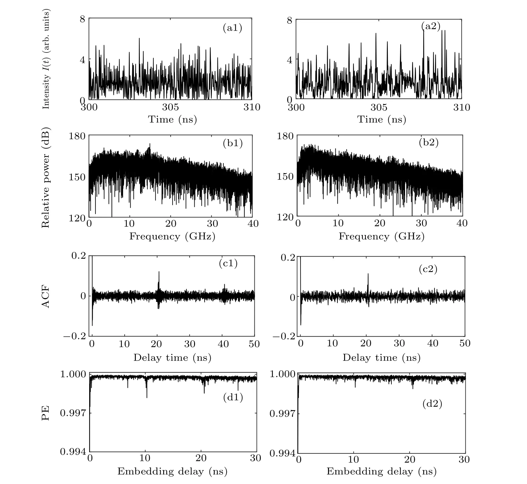
Fig. 4. (a1) and (a2) Time series, (b1) and (b2) power spectra, (c1) and (c2) ACF, (d1) and (d2) PE for SL1 (left column) and SL2 (right column). Δf21=10 GHz,c12i=c21i=3 ns-1,I=1.8Ith.
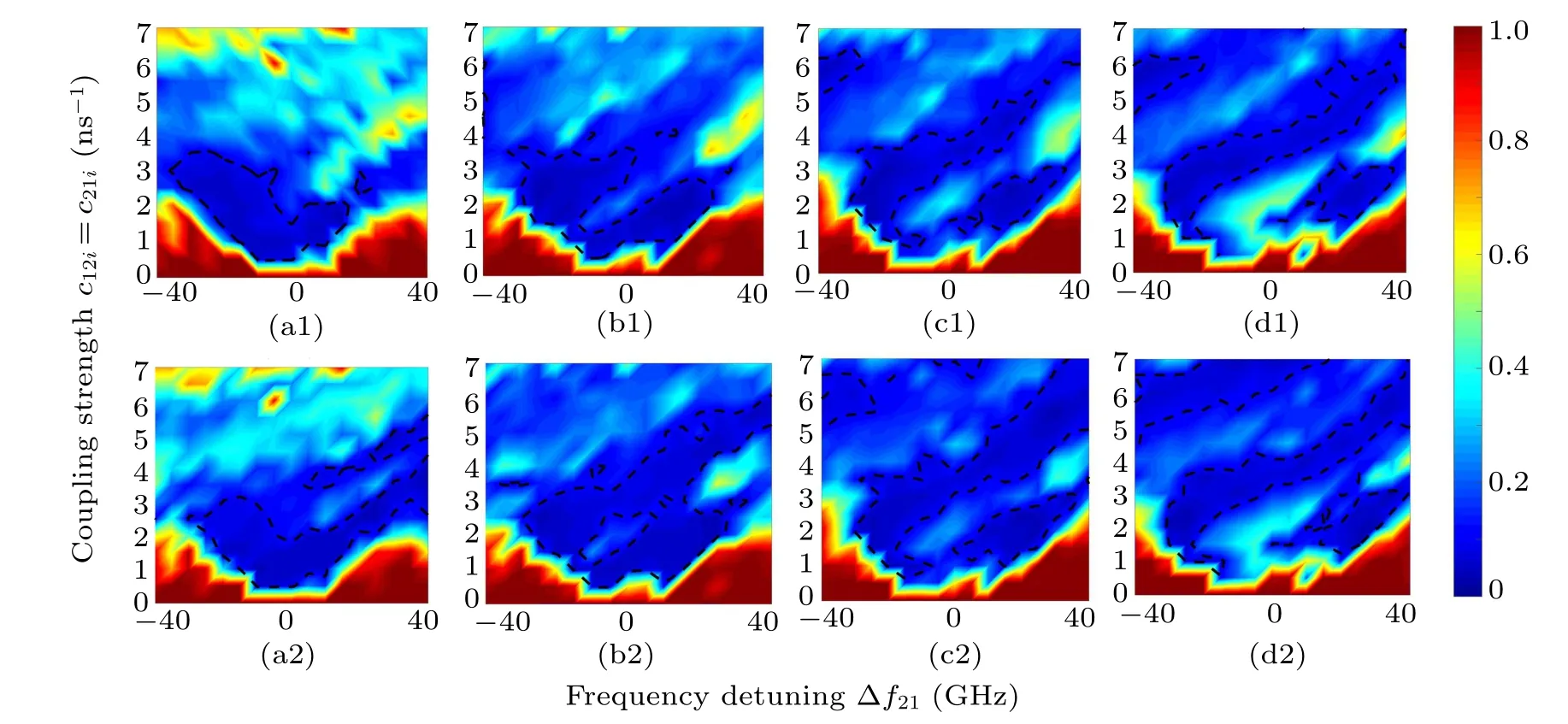
Fig.5. Map of TDS evolution in the parameter space of detuning and coupling strength for MCSLs with random optical injection: (a1)and(a2)I=1.4Ith,(b1)and(b2)I=1.8Ith,(c1)and(c2)I=2.2Ith,(d1)and(d2)I=2.6Ith. Upper:SL1,lower:SL2. The dashed lines correspond to ACF subpeak=0.1.
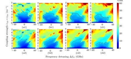
Fig.6. Map of BW evolution in the parameter space of detuning and coupling strength for MCSLs with random optical injection: (a1)and(a2)I=1.4Ith,(b1)and(b2)I=1.8Ith,(c1)and(c2)I=2.2Ith,(d1)and(d2)I=2.6Ith. Upper: SL1,lower: SL2. The dashed lines correspond to 20 GHz for BW.
Figure 6 depicts the map of BW evolution in the parameter space of detuning and coupling strength for different bias currents. The ranges with <20 GHz BW are highlighted by the contour lines with BW =20 GHz. As mentioned above,BWs of both SLs are enhanced with the increase of coupling strength.[16,17,40,41,54]For appropriate coupling strength, the enhanced BW can be obtained with larger detuning,since the new frequency components in the vicinity of frequency detuning are generated due to the beating of SL1 and SL2.[41]In addition,with the increasing bias current,in parameter ranges with good TDS suppression shown in Fig. 5, the range with>20 GHz BW is also broadened, which means that increasing current can significantly expand the optimized parameter range for larger BW.Meanwhile,the range for optimized TDS(ACF subpeak <0.1)is not shrunk.
3.2. Two-channel 200 Gbits/s physical random number generation using chaos outputs with enhanced bandwidth and TDS suppression
In this section,we analyze the performance of the physical random number sequence generated by the post-processing of the chaotic signals from the system. Various methods have been proposed.[12–22]Here, we use the post-processing approach proposed in Ref.[19]as shown in Fig.7. The chaotic signals from the two MCSLs are respectively converted into 8-bit binary sequences with an analogue-digital converter(ADC)with sampling rate of 50 Gs/s. A four-least-significant-bit(4-LSB) sequence is selected. The generated 4-bit binary sequence and delayed version are then processed with exclusive-OR (XOR) operation (the used delay time for SL1 and SL2 outputs are 25 ns and 46.5 ns,respectively).
As an example,according to Figs.5 and 6,we select the following parameters: c12i=c21i=2 ns-1,Δ f21=-30 GHz,I =2.6Ith. Figures 8(a), 8(b) and 8(c) show the power spectrum, ACF and CCF of chaos outputs, respectively. Due to the larger detuning,larger BWs for SL1 and SL2 are obtained(the BWs of SL1 and SL2 are ~20.6 and ~25.1 GHz, respectively). The corresponding ACF subpeaks are ~0.05 and~0.04 respectively. The correlation peaks of CCF are well within ±0.05 [see Fig. 8(c)], confirming the much weak correlation between the chaos outputs of SL1 and SL2. These higher BW, good TDS suppression and very weak crosscorrelation are helpful for generating the high-quality random sequences.

Fig. 7. Flow chart of post-processing for high-speed physical random number generation.


Fig.8. Power spectrum(a),ACF(b)and CCF(c)of chaos outputs under c12i=c21i=2 ns-1,Δf21=-30 GHz,I=2.6Ith.
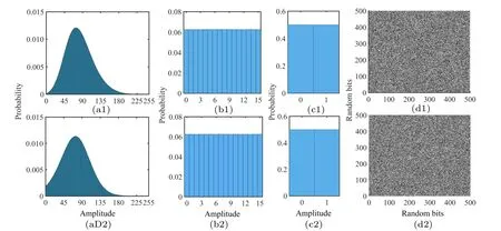
Fig.9. Characterization of generated random bit streams. (a1)and(a2)Probability of 256 digital amplitude of the generated binary sequences after ADC converted to decimal system; (b1) and (b2) probability of 16 digital amplitude of the generated binary sequences after 4-LSB selection and XOR operation converted to decimal system;(c1)and(c2)probability of 0 and 1 in random bit stream after 4-LSB selection and XOR;(d1)and(d2)example of 500×500 random bit sequence after 4-LSB selection and XOR operation on a two-dimensional plane. In(d1)and(d2),bits of 1 and 0 are converted into white and black dots,respectively. Upper: SL1,lower: SL2. The used length of samples is 100 Mbit.

Fig.10. ACF of the generated random sequences after 4-LSB selection and XOR operation for SL1(a)and SL2(b). The used length of samples is 100 Mbit.


We then use the NIST SP 800-22 suite[58]to test the randomness of the generated two-channel 4-LSB random number sequences. We take 1000 groups of 1 Mbit data points used for test, with a significance level of α = 0.01. After the test, two results will be obtained: P-value and proportion value. Only when the P-value(uniformity of p-value)is greater than 0.0001 and the proportion satisfying p-value >α in the range of 0.99±0.0094392 can pass the test.[14–22]The results are listed in Table 1. For the selected system parameters, the binary sequences generated by the two SLs passed all of the NIST test standard. Therefore,the proposed system can simultaneously generate two-channel random number sequences,with the rate of 200 Gbits/s(=50 Gs/s×4 LSB)for each channel.
Finally, CCF of the generated sequences between SL1 and SL2 (after 4-LSB and XOR) is plotted in Fig. 11, where binary data with a length of 0.1 Mbit is used considering the computation efficiency due to longer delay time. The CCF across the delay of-40–40 ns is close to zero, implying that the two-channel random sequences are almost independent.In other words, the residual weak correlation between SL1 and SL2[see Fig.8(c)]can be eliminated radically after postprocessing. Therefore, this system could have a potential for generating a higher rate of 400 Gbits/s by interleaving the twochannel binary outputs.[16]
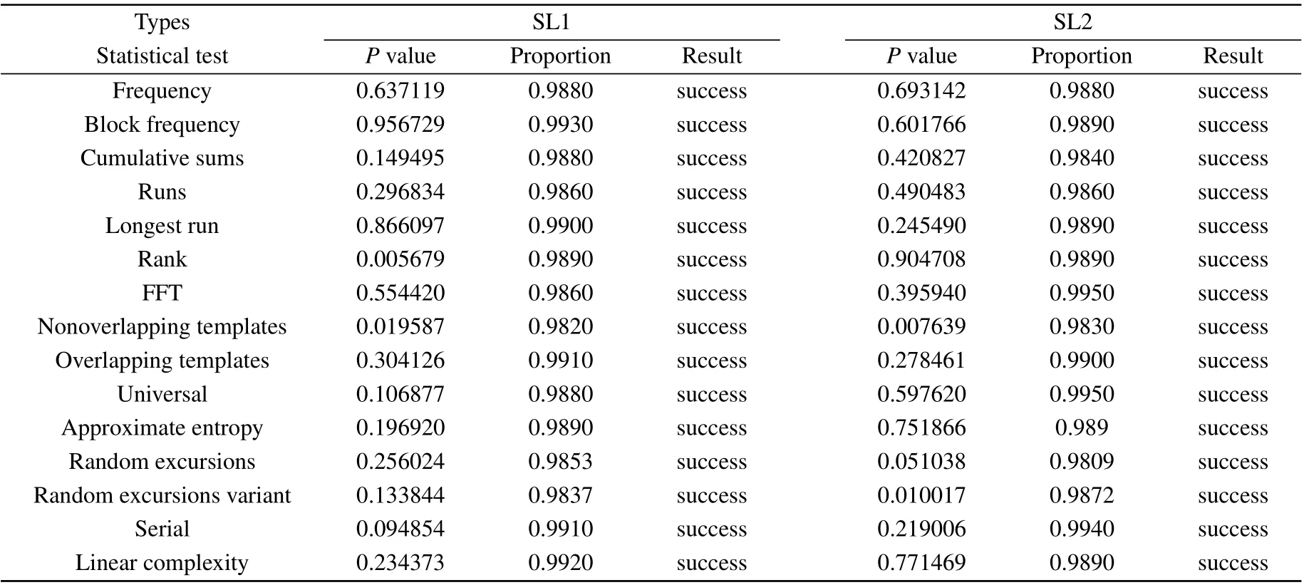
Table 1. Results of statistical test using NIST SP 800-22 for a set of 1000 sequences of 1 Mbit. Both of test results for SL1 and SL2 are demonstrated. For tests which produce multiple P-values and proportions,the worst case is shown.[16–18]

Fig.11. CCF of generated random sequences from SL1 and SL2 after 4-LSB and XOR operation.
4. Conclusion
In summary,a novel structure based on random-injectionbased MCSLs has been proposed and designed for simultaneously generating two-channel chaos outputs with BW enhancement and TDS elimination over a wide range of parameters. The effects of frequency detuning, coupling strength and injected current on chaos characteristics have been numerically discussed detailedly. The results show that, under certain parameters, the system can achieve BW of more than 20 GHz with perfect TDS cancellation;the broader parameter ranges for higher BW and lower TDS can be obtained by properly selecting injected current. As a practical application, we also analyze the feasibility for generating two-channel highspeed physical random sequences(200 Gbits/s for each channel). Our work is meaningful on structure design and parameter optimization for high-quality chaotic laser sources, and may find applications in high-resolution chaos-based lidars,OTDRs,high-speed secure communications and PRNGs,etc.
- Chinese Physics B的其它文章
- Two-dimensional finite element mesh generation algorithm for electromagnetic field calculation*
- Stable water droplets on composite structures formed by embedded water into fully hydroxylated β-cristobalite silica*
- Surface active agents stabilize nanodroplets and enhance haze formation*
- Synchronization mechanism of clapping rhythms in mutual interacting individuals*
- Theoretical study of the hyperfine interaction constants,Land´e g-factors,and electric quadrupole moments for the low-lying states of the 61Niq+(q=11,12,14,and 15)ions*
- Ultrafast photoionization of ions and molecules by orthogonally polarized intense laser pulses: Effects of the time delay*

