Undrained Stability Analysis of Three-Dimensional Rectangular Trapdoor in Clay
YINXiaojun,XIEJun(谢骏)
1 College of Mining Engineering, Heilongjiang University of Science and Technology, Harbin 150027, China2 Independent Senior Geotechnical Engineering Consultant, Toronto ON L4C 9G1, Canada
Abstract: A new collapse model of the trapdoors, three-dimensional rectangular trapdoor (3DRT), is presented for ground surface collapse. Undrained stability of 3DRT is examined with the upper bound method of plasticity limit analysis theory. The soil where the trapdoors are located is assumed to be a perfectly plastic model with a Tresca yield criterion. Block analysis technique is employed to investigate the collapse of 3DRT. The model is divided into five different block types and added up to ten rigid blocks. According to the law of conservation of energy, the critical stability ratios of 3DRT are obtained through a search proceeding. The results of upper bound solution for 3DRT are given, and three trapdoor models with depth various are discussed during the application in the stability analysis of square trapdoors. The critical stability ratios can be used in the design of underground excavation and support force.
Key words: three-dimensional rectangular trapdoor; upper bound solution; stability ratio; rigid block; block analysis technique
Introduction
On April 11, 2011, a surface of Shiliuzhuang Road in Beijin city suddenly collapsed and became a big hole. On December 26, 2012, the surface on Cross main road, Taiyuan city subsided and became a trapdoor tens of meters wide, as shown in Figs. 1-2. Ground surface collapse becomes a serious problem in the urban environment. It may be caused by many reasons, such as excess of underground water exploiting,ground overloading, lack of support and the other unknowing reasons. Once ground cave in, an empty hole appears in the subsurface, and no structures support upon the above ground soil and structures so that the ground surface collapse makes a trapdoor. This phenomenon is in general called “trapdoor problems”.
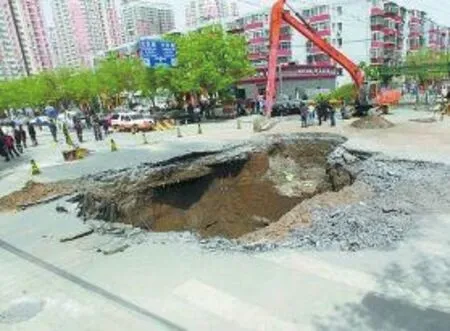
Fig. 1 Shiliuzhuang road in Benjin city
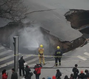
Fig. 2 Cross main road in Taiyuan city
Trapdoor collapse analysis is used to investigate stability of tunnel roof, arch and other structures in soil. The trapdoor problem, originally proposed and investigated by Terzaghi[1]in 1936. After that, the problem has been experimentally studied widely. Davisetal.[2]analyzed trapdoor of tunnel problem, showed thatNc(a dimensionless stability factor) could be bracketed quite closely using lower bounds derived from some simple stress fields, together with the upper bound derived from the vertical slip mechanism for small cover ratios. Davisetal.[2-3]refined the upper bound solution using a three-parameter rigid block mechanism. After then, many researchers[4-7]have used finite element limit analysis to obtain lower and upper bound solution onNcfor cover ratios in the range of 0 to 10. Elastic-plastic finite element results suggest upper bound solutionNc=2H/Bmust be very close to exactness whenH/Bis small. Martin[8]analyzed undrained collapse of a shallow trapdoor, got a slip-line solution. Suraparb[9]presented a plastic solution of the active collapse of planar trapdoor in non-homogeneous clay that have a linear increase of strength with depth. Some other researchers[10-17]also presented solutions of trapdoor problems for active and passive modes by using model tests in laboratory.
The stability analysis of 3D square trapdoor was carried by Rahimetal.[18]with the upper bound method. The collapse model of the trapdoor was made up of several rigid blocks, and the 3D square trapdoor is a local surface collapse model.
In the following sections, 3D rectangular trapdoor (3DRT) model is developed to fill the gap between the 3D square trapdoor (local collapse) and the 2D trapdoor (3D unlimited length trapdoor). Firstly, simple block models (3D square trapdoor, 3DRT to 2D trapdoor) in shallow soil are discussed. Secondly, the analysis models of 2D trapdoors and 3D square trapdoor are reviewed, and 3DRT model is created and the stability analysis is discussed in the next step. Finally, the relationships among 2D trapdoor, 3D square trapdoor and 3DRT are highlighted, and the result of stability analysis for 3DRT is concluded.
1 Upper Bound Solutions for 3D Trapdoors
The upper bound theorem of limit analysis method is applied in the following sections. The upper bound theorem states[3]that if a work calculation is performed for kinenatically admissible collapse mechanism, then the loads thus deduced will be higher than (or equal to) those for collapse.
A stability ratioNis used as a criterion for stability analysis of trapdoors in this paper as the previous researchers used. The basic equation[2-3]is:
(1)
where,σsis the surcharge on the ground surface;σtis the support force in the excavation;γis the unit weight of soil;His the height of the trapdoor soil;Cuis the cohesive of soil.
1.1 Simple block models
The stability ratios (N) of three block models[10]are as follows.
For 2D trapdoor:
(2)
For 3D square (D=B) and 3D rectangular trapdoor:

(3)
where,Dis the length andBis the width of the trapdoors.
1.2 2D trapdoor and 3D square trapdoor
A 3D square trapdoor model and 3D unlimited length trapdoor (2D trapdoor) models are shown in Figs. 3-4.

Fig. 3 Upper bound mechanism of 2D trapdoor
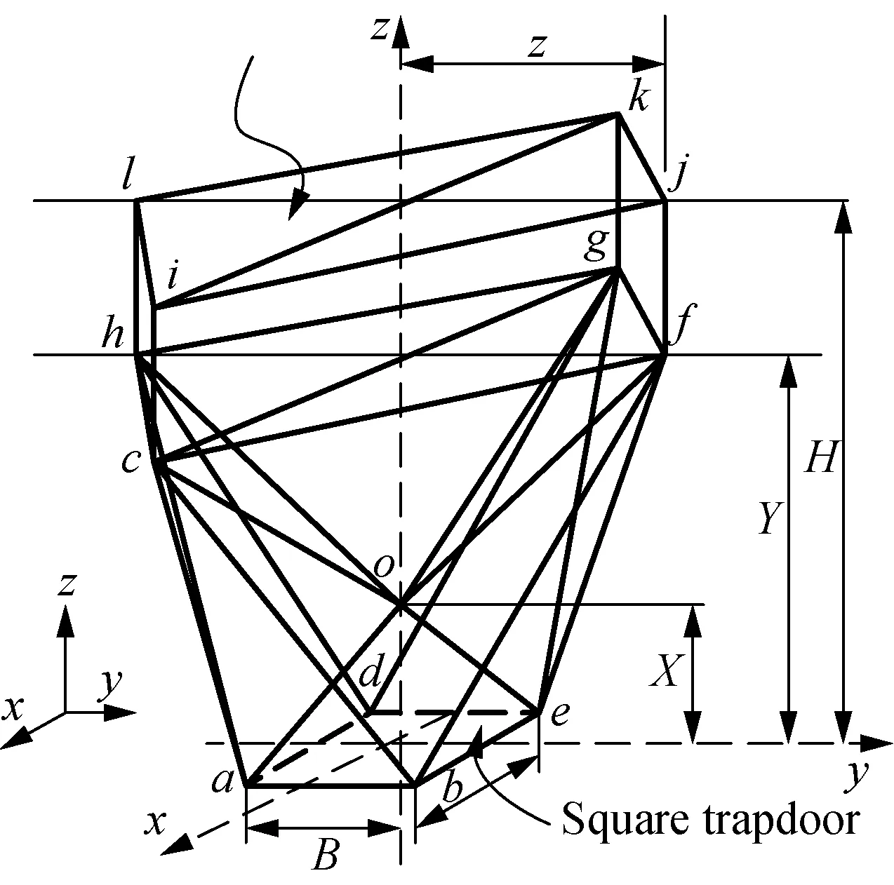
Fig. 4 Upper bound mechanism of 3D square trapdoor
In Fig. 3, the mechanism is composed of blocka0, blockb0, blockc0and blockd0.His the height of 2D trapdoor.Bis the width of 2D trapdoor.αis an intersection angle between sides of blocka0and horizontal plane.βis an intersection angle between sides of blockb0and stability zone.γis an intersection angle between sides of blockb0and blockc0.X,YandZare intermediate variables.
Figure 4 indicates mechanism of 3D square trapdoor, and the parameters are the same meaning as Fig. 3 except thatBequals toD.
2 3DRT
2.1 Basic model
In order to get a collapse mechanism of a rectangular trapdoor, a six-variable model for a rectangular trapdoor is built in Figs. 5-6. The width and the length of the trapdoor areBandD.
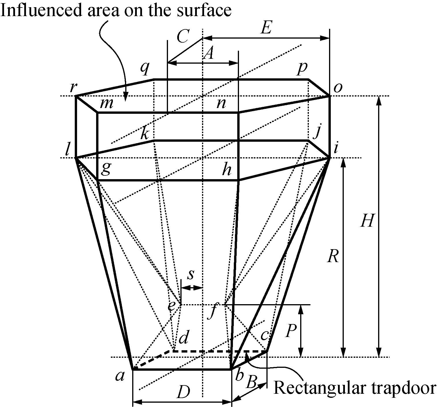
Fig. 5 Mechanism of 3D rectangular trapdoor
2.2 Types of rigid block for the mechanism
Based on the collapse mechanism of 3DRT, the soil masses acting on the mechanism is divided into five types, adding up to ten rigid blocks. Block I expresses bottom of 3DRT, block V expresses top of 3DRT, block II-IV indicate the sides of 3DRT. Due to the symmetry of the model, block II and block V have two blocks, and block IV has four blocks. Types of rigid blocks are shown in Fig. 6, and the numbers of rigid blocks are shown in Table 1.
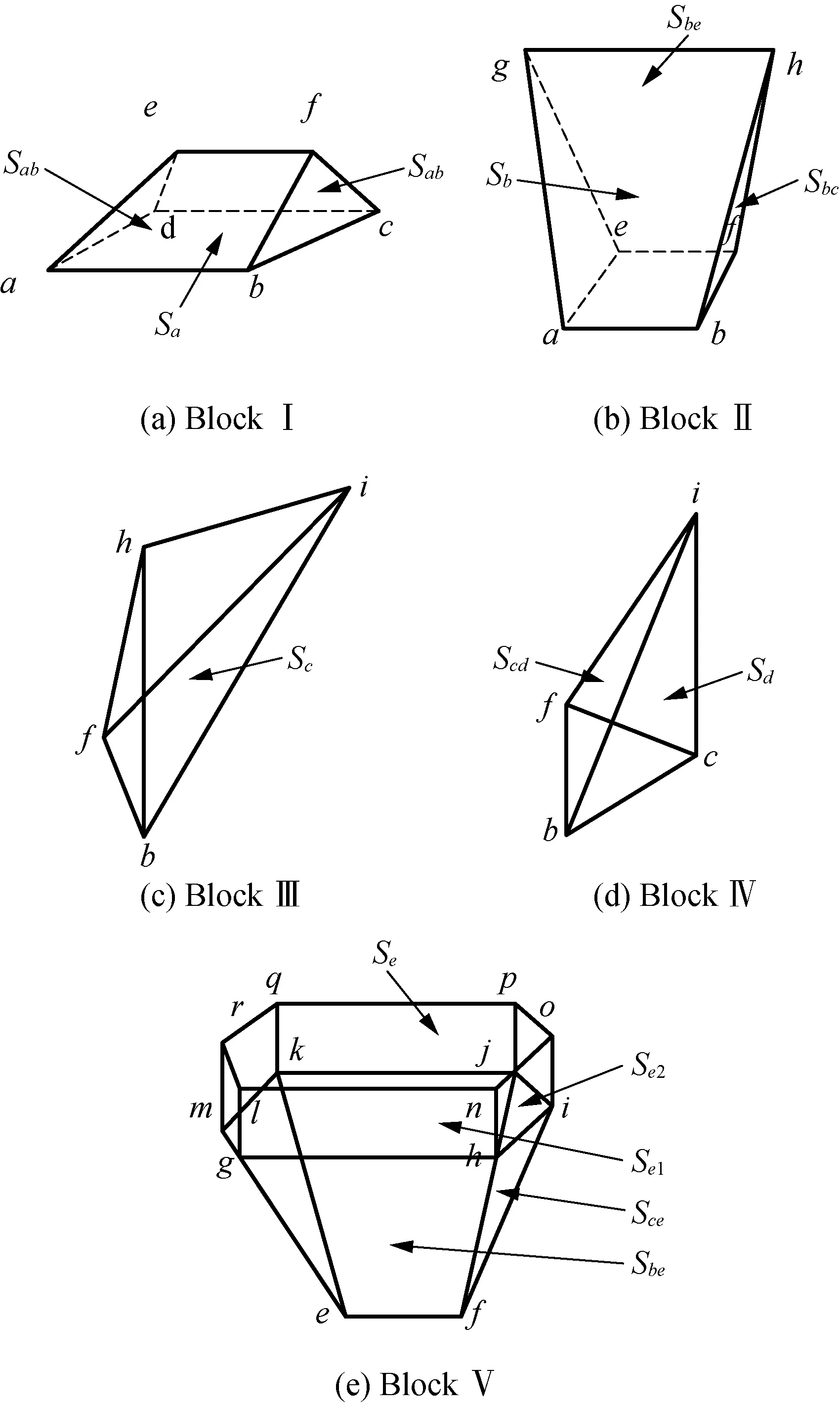
Fig. 6 Blocks of a rectangular trapdoor

Table 1 Types and numbers of blocks for the rectangular trapdoor
2.2.1Areasofmechanism
There are six variables (P,R,S,E,A,C) in the model and the co-ordinates of the corners of the rectangular trapdoor are:
a(B/2, -D/2, 0),b(B/2,D/2, 0),
c( -B/2,D/2, 0),d(-B/2, -D/2, 0 ),
e(0, -S,P),f(0,S,P),
g(C, -A,R),h(C,A,R),
i( 0,E,R),j( -C,A,R)
k( -C, -A,R),l( 0, -E,R),
m(C, -A,H),n(C,A,H),
o( 0,E,H),p( -C,A,H),
q( -C, -A,H),r( 0, -E,H).
The areas on the blocks can be obtained with the Vector Arithmetic. Here, thirty-four areas on all blocks are shown in Talbe 2.

Table 2 Surfaces and numbers for the rectangular trapdoor
The surface areas can be calculated using the Vector Arithmetic as well.
2.2.2Volumesofmechanism
All volumes can be obtained using the Vector Arithmetic. They are as follows:
Then Narcissus implored13 his faithful friend Melinette to send the Princess such dreams of him as should make her recognise him as a friend when he actually appeared before her eyes; and this device was so successful that the Princess quite dreaded14 the cessation of these amusing dreams, in which a certain Prince Narcissus was such a delightful15 lover and companion

(4)
2.2.3Velocitiesofmechanism
We can assume that the velocity of the blockA0is a unit velocity (Ua= 1) and the direction cosines of a unit velocity areA1=0,A2=0,A3=-1. The velocity of the blockEisUeand the direction cosines of a unit velocity areE1=0,E2=0,E3=-1. The magnitude ofUeis:

(5)
If blockA0and blockB0share the surfaceabef(Sabin Fig. 6), the projections of the unit vectors of the velocities in the blocksA0andB0on three axes of the co-ordinates are (A1,A2,A3) and (B1,B2,B3). The projections of the vectornof theSabare (n1,n2,n3). The velocity of the blockB0can be obtained based on zero displacement (no gap between two blocks) in the direction of the vectorn:

The velocityUabon theSabis the difference between the velocitiesUaandUb. If the projections ofUabonx-axis,y-axis andz-axis areUab1,Uab2andUab3, they are:
Uabi=UaAi-UbBi,i= 1, 2, 3.
(7)
The magnitude of the velocityUabis:

(8)
The magnitudes of all velocities (Ub,Uc,Ud,Uab,Ubc,Ube,Ucd,Uce) can be calculated by Eqs. (6)-(8).
3 Stability Ratios of the Mechanism
The equation of external work and internal energy must be equal for the calculation of stability ratios. The external work of the rectangular trapdoor is:
W=Ws-Wt+Wγ=
σsSeUe-σtSaUa+γ(VAUa+2VBUbB3+
(9)
whereWsis the work ofσs,Wtis the work ofσt,Wγis the work of soil weight,Seis the influenced area on the surface, andUeandVE0are the velocity and the volume of the blockE0respectively.B3,C3andD3are the direction cosines of the velocityUb,UcandUdwithZaxis respectively.
In this rectangular trapdoor model, the soil masses are also assumed as rigid blocks and the internal soil deformation rate of energy dissipation is equal to zero. Total energy is equal to the dissipating energy on the surfaces of velocity discontinuity, that is:

(10)
whereSiandUi(i=ab,b,c,d, …) are the areas and the velocities on the planes of blocks andVI(I=A,B,C, …) are the volumes of blocks.γis the unit weight of soil andCuis the undrained shear strength of soil.
Substituting Eqs. (9)-(10) into the equation,E=W, the stability ratio of the rectangular trapdoor can be obtained as follows. A computer program was developed to do calculation.
where,
G(Si,Ui)=2[(SabUab+SbUb+SdUd+SbeUbe+
SadUad+SelUe]+2(SbcUbc+
ScUc+ScdUcd+SceUce+
Se2Ue)],
F(Si,Vi,Ui,Bi,Ci,Di) =
VAUa+2VBUbB3-SeUeR+4VcUcC3+
2VDUdD3+VE02Ee,
where,VE02is a part ofVE0of the prism (block Ⅴ in Fig. 6).
Equation (11) contains a large number of variables, and the upper bound solution of 3SRT can be obtained by using Matlab14 software to optimize the parameters in the equation.
4 Results and Discussion
WhenD/B=1, the model is a square trapdoor. With the increase ofD/Bin Fig. 7, the stability ratios (N) will change to smaller at the same values ofH/B. IfD/Bis infinite (that isD≫B), the problem of 3DRT transforms into that of 2D trapdoors, then stability ratio of 3DRT equals to that of 2D trapdoors, that is Gunn’s result is the lowest boundary of the stability ratio of 3DRT.
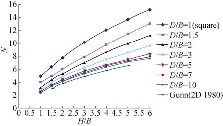
Fig. 7 Upper bound solution for rectangular trapdoors

Fig. 8 Upper bounds solutions for 3D square and 3DRT(H= 5 m)
Figure 8 shows that the stability ratios compared the 3DRT with 3D square trapdoor in the depth of 5 m under the ground surface. The largest value of stability ratios is that of 3D square trapdoor. With the increase ofD/B, the stability ratio becomes smaller. WhenDis a infinite value,Nwould be close to Gunn’s result (2D case). The stability ratio of rectangular trapdoor is the value between that of square trapdoor and 2D trapdoor.
Figure 9 shows the upper bound solutions of square trapdoors from 3D block, 3D square model and 3D rectangular model when the width is equal to the length of the trapdoor (D=B). Obviously, whenH/B>2.5 in Fig. 10, the stability ratios of 3D square model obtain the lowest values.When 1.5≤H/B≤2.5, it is reasonable to choose the stability ratios from 3D rectangular model. When the square trapdoor is at shallow soil, a simple clock model is a better choose to get the lowest values of the stability ratio (N).

Fig. 9 Square trapdoor upper bounds solution for 3 models
Based on the analyzed results in Fig. 10, different 3D trapdoor models should be used to obtain the lowest stability ratios of square trapdoors with different soil depths.

Fig. 10 Upper bound solution of 3D square trapdoor
5 Conclusions
A 3DRT trapdoor model was developed and the upper bound theorem of limit analysis method was adopted to investigate the stability of 3 DRT in soil under the Tresca yield criterion. It fills the gap of stability ratio between that of 3D square trapdoor and 2D trapdoor.
To analyze the stability of local collapse, the lower supporting force for 3D trapdoor is required than that from 2D tunnels. Using 2D trapdoor model to analyze the local stability in tunnels will overestimate the support force. It has an important meaning in engineering practice.
 Journal of Donghua University(English Edition)2020年4期
- Journal of Donghua University(English Edition)的其它文章
- Emergency Evacuation Plan of the Louvre Based on Cellular Automata Superposition Model
- Comprehensive Evaluation Method for Safety Performance of Automobile Textiles
- Method for Detecting Fluff Quality of Fabric Surface Based on Support Vector Machine
- Preserving Data Privacy in Speech Data Publishing
- Zero-Sequence Current Suppression Strategy for Open-End Winding Permanent Magnet Synchronous Motor Based on Model Predictive Control
- Improved Fibroblast Adhesion and Proliferation by Controlling Multi-level Structure of Polycaprolactone Microfiber
