Research on Measurement Method of Muffler Performance under High Temperature andHigh-Speed Airflow Conditions
Liping Xie, Chihua Lu,2, Zhien Liu,2, and Yawei Zhu
(1. Hubei Key Laboratory of Advanced Technology of Automotive Components, Wuhan University of Technology, Wuhan 430070, China;2. Hubei Collaborative Innovation Center for Automotive Components Technology, Wuhan 430070, China)
Abstract: Ignoring the influence of flow velocity and flow temperature on muffling performance,performance tests were conducted without airflow in the development phase of the muffler which accounts to the difficulty of obtaining a perfect match between the actual noise reduction effect and the design goal. Based on the two-load test theory, a set of high-temperature and high-speed airflow simulation measurement devices for the muffler has been built. In order to avoid the impact of high-temperature and high-speed airflow on the sensor, a high temperature resistant sensor holder has been designed for the test rig. The sound pressure has been measured in the pipe by using the lead-out measurement. In addition, a variable impedance load is placed at the end of the test tube to realize the switch between two different impedance loads by the wave handle of the variable impedance load. A sound source correction method is proposed to decrease the random fluctuation of the spectral characteristics of the output noise signal, which is caused by the acoustic impedance variation at the connection between the transition pipeline and the combined sound source system.Finally, an acoustic software has been used to calculate the transmission loss of the muffler in the presence of high temperature airflow. In comparing the experimental measurements and the simulation results, the small difference shows that: the bench not only can effectively simulate high-temperature and flow velocity environment of the engine but also accurately test the transmission loss of the muffler.
Key words: muffler;lead-out measurement;variable load;source correction;transmission loss
The exhaust muffler is used as a main method of eliminating automobile exhaust noise, and its design and development process often requires a no-flow state transmission loss test and engine muffler performance test. Among them,the traditional test bench which works at normal temperatures and no-flow conditions cannot realistically simulate the actual working condition of the muffler, so the calculated transmission loss and actual value are vastly different,which reduces the research and development efficiency of the muffler. The preliminary preparation period of the muffler performance test under the engine test bench is too long. During the test, the combustion noise and mechanical noise of the engine often interfere with the exhaust noise test. The exhaust gas generated during the engine exhaust process can cause air pollution.At the same time, building an engine test bench requires a lot of manpower and material resources, and it is not possible to individually adjust the airflow and temperature. Therefore, it is necessary to carry out related technology research on the test bench of engine exhaust muffler. To design the test bench which can simulate actual working conditions, a study of sound source characteristics of engine and related test technologies has been done, which laid a foundation for the research of different types of mufflers[1−4]. In order to observe the change of the reflection coefficient at the end of the pipeline under high temperature and high flow conditions,a high-precision reflection coefficient test device with multiple working conditions was built,which can effectively control the temperature and flow velocity variation range. Furthermore, the corresponding sensor supporter is designed to enable sensors to measure the sound pressure in the pipeline. However, this support was not introduced in detail[5]. Generating high speed airflow by the high-speed fan, while warming airflow using a high-power electric heating wire, a muffler performance test device at high temperature and high speed can simulate the special working conditions of a real muffler. However, the error of high-temperature-and-high-speed airflow on the sensor is not considered[6].
It is of great significance to simulate the real working environment of mufflers under high temperature and high pressure, however, conventional sound pressure sensors have difficulty withstanding the impact of high speed and high temperature airflow[7]. At present, some engineers have adopted high-value probe sensors to measure sound pressure under extreme environments,which can withstand temperatures up to 700 degrees Celsius. However, this kind of sensor has a small detection range such that it cannot meet the measurement requirements of high noise intensity in the exhaust system. In addition, the two-load method also cannot work in this condition, because the airflow must be interrupted bef ore changing the load. After the load is replaced,it is difficult to restore the test environment to be completely consistent with the original one,and so measurement error exists. For the combined sound source system, the transition pipe designed with different structures will lead to changes in acoustic impedance, which will interfere with the acoustic signal output, making the spectrum characteristics of the final output noise signal fluctuate randomly and unable to guarantee the accuracy of measurement data.
Here we use the finite element software to analyze the influence of temperature field and flow field on the acoustic characteristics of the pipeline[8]. Based on the traditional two load method test[9], a muffler simulation device with the high-temperature-and-high-speed-airflow is designed[10]. A high-speed fan and high-power airflow heating device have been designed to simulate the real working environment of the muffler,and the High-temperature resistant sensor support has been designed to help sensors measure the sound pressure in the pipe and to avoid damage from the high-temperature airflow. In addition, a variable impedance load is placed at the end of the test tube to realize the quick switching between two different impedance loads by the wave handle. A correction method of the sound source signal is proposed to compensate the error made by the sound source combination system. Finally, the acoustic software has been used to calculate the transmission loss of the muffler in the presence of high temperature airflow, and this result is compared with experimental measurements to verify the effectiveness of the simulated platform.
1 Structure Design of Test Bench
As shown in Fig.1, the high-temperature and high-speed airflow simulation test device designed in this paper is mainly composed of four parts: airflow generating device, airflow heating device, the sound signal generator and transmission loss test system.

Fig. 1 Schematic diagram of the high-temperature high-speed airflow simulation test device
1.1 Design of airflow generating device
During the operation of the airflow generating device, the partition wall and the hose cannot eliminate the impact of aerodynamic noise, as depicted in Fig.2. On the contrary, noise within a specific frequency spectrum will be generated,and the noise signal emitted by the sound source system will be superimposed due to this wall and hose, resulting in the instability of the output noise signal spectrum and also affecting the test results. Therefore, in order to improve the signalto-noise ratio in the test pipeline, an absolute muffler[11]was designed in combination with the noise attenuation characteristics of the impedance composite muffler to ensure that the background noise is at least 15dB lower than the noise signal.
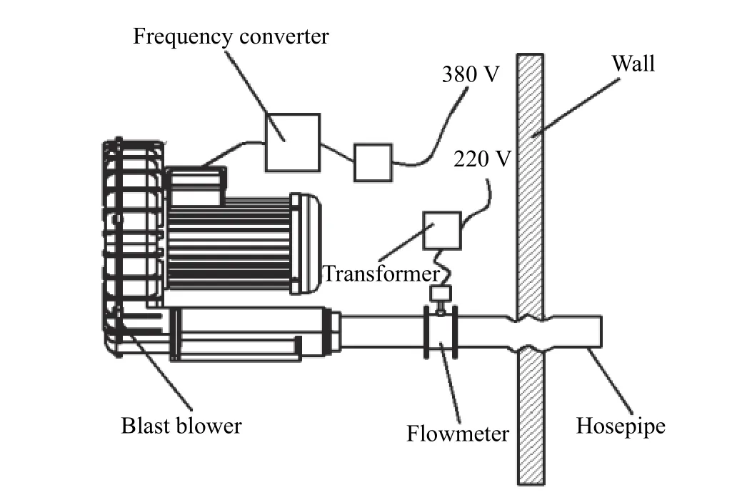
Fig. 2 Structure of airflow generating device
1.2 Design of airflow heating device
A high-speed airflow rapid heating device was designed to explore the influence of high temperature gas on the transmission loss of the muffler[12]. It is mainly composed of a diversion part, heating part, supporting heat insulation part and the control system. The whole heating device is convenient to disassemble, assemble and modulate as shown in Fig.3.
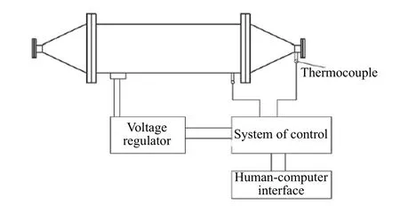
Fig. 3 Structure diagram of airflow heating device
The structural design of the airflow heating device satisfies the theoretical requirements. For further verification, the simplified three-dimensional model of the airflow heating device is imported into Star-CCM+ for generating the flow field and temperature field coupling analysis. Different inlet mass flow rates are set to determine the operating range of the heating device (0.03 kg/s-0.14 kg/s, a total of 12 sets of data), and repeating simulation analysis work will obtain the entrance velocity, outlet velocity, entrance temperature, outlet temperature, pressure. The simulation results are shown in Tab.1
The data in Tab.1 is plotted as the surface map in Fig.4. It can be seen from Fig.4 that the outlet temperature decreases gradually with increasing mass flow rates. The experiment under
various working conditions can be simulated by adjusting the frequency converter to control the velocity of the blower and the operating power of the airflow heating device. This demonstration of heating the airflow at any point in the shaded part indicates that the designed heater meets the operational requirements.

Tab. 1 Simulation results under different mass flow conditions
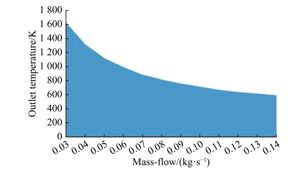
Fig. 4 Heating range of the heating system
1.3 Design of the sound signal generator
Comparing the acoustic characteristics of different types of speakers, the low-frequency speaker and the medium-frequency speaker are combined and arranged vertically on the test pipe through the transition duct, and the noise signal is provided to the pipeline test system in the form of combined sound[13]. The structural design is shown in Fig.5.

Fig. 5 Schematic diagram of the combined sound source
The final acoustic signal will be inperfect due to the interference caused by the layout of the transition pipeline. In order to solve the problem of the random fluctuations in the spectral characteristics of the output noise signal,which is caused by the change in acoustic impedance at the junction of the transition pipeline and the combined sound source system. A correction method for combining noise signals is proposed. This method is based on the four-sensor method used to measure the acoustic impedance of the transition pipeline[14]. According to the transfer matrix of transition pipeline, the noise at the pipe orifice, which is the output of a random white noise excitation source, is used as the output sound pressure signal to obtain the input sound pressure signal of the combined sound source system and realize the sound signal compensation of the system[15].
Without considering the sound energy loss caused by the friction between the gas and the rigid wall, the four-stage parameters of the straight pipe with equal sections can be expressed by

wherelis the distance between the reference point and the load section,cis the sound velocity,kis wave number, andSis the pipe crosssectional area.
In this paper, the sound source compensation test device is used to connect the test pipe with the combined sound source system by means of equal sectioned transition pipe. The effect of straight tube length on the accuracy of measured impedance is ignored. With the sound source combination system as the input terminal and the pipe mouth noise as the output terminal,the whole connection structure can be used as the pipeline system with equal sections, and Eq.(1) can be directly used for sound source compensation. Its expression is

wherePris the ideal output sound pressure of the nozzle after Fourier transform, and the noise of the nozzle output by random white noise can be taken as a reference.Zris the acoustic impedance radiated from the nozzle of a straight tube,which can be obtained by empirical formula[10].Plcan be obtained from the transfer matrix as the input sound pressure of the combined sound source system.Zlis the acoustic impedance of the sound source combination system obtained by the transfer function method.
Fig.6 shows that the sound pressure output curve of the combined sound source system before and after correction. Fig.6a is the noise of before the correction, the spectral characteristics of the output noise signal of the combined sound source system are not uniform. The sound pressure level fluctuates with frequency, and the fluctuation of the frequency response curve is larger.Fig.6b is the noise of after the correction, the acoustic signal outputted by the sound source combination system fluctuates smoothly over a wide test frequency range, and the power distribution is uniform, which satisfies the test requirements and ensures the accuracy of the measurement technology.
1.4 Design of transmission loss test system
As shown in Fig.7, the transmission-loss test muffler is connected by both a front and a rear tube. High temperature sensor supports are arranged on the tube before and after the test to measure the sound pressure signal. A variable impedance load is installed on the tail of the tube away from the muffler to be tested.
When using the two-load method to measure the transmission loss of the muffler, it is necessary to set a load with a different impedance value at the end of the test device. The operation of changing the load on the high-temperature and high-speed test bench is tedious, and the consistency of the measuring environment before and after the change cannot be guaranteed.Therefore, the variable impedance load is used to realize the quick change of the terminal load, and the sectional view is as shown in Fig.8.

Fig. 6 Noise signal of combined sound source

Fig. 7 Structure diagram of test system of transmission loss

Fig. 8 Cross section of variable load
A sound-absorbing material is filled between the tapered tube and the perforated outer tube.The perforated inner tube and the perforated outer tube are provided with a plurality of rows of through-holes in the axial direction of the tube wall. The through-hole diameters of the perforated inner and outer pipes are 8 mm. Eight small holes in each row are evenly distributed along the circumferential direction of the pipe wall, and 27 rows of small holes are distributed along the axis of the pipe wall at intervals of 15 mm. The impedance value of the load is changed by rotating the perforated inner tube with a handle to overlap or stagger the perforated inner tube and the perforated outer tube. The transmission loss of the muffler can be calculated by measuring the sound pressure signals of the upper and lower reaches respectively. Moreover, the horn mouth is arranged at the tail of the perforated tube to reduce the air flow speed and thereby reduce the airflow noise.
2 Design and Performance Analysis of High Temperature Sensor Support
When measuring the noise inside the pipeline in the high-speed, high-temperature airflow conditions, the high-temperature high-speed gas will affect the measurement accuracy of the barrier inside the microphone if the sensor is directly embedded in the test pipeline. The probe is too thin to be arranged on the test pipe, and the probe head is often blocked by the smoke in the exhaust pipe. Moreover, measuring in a high temperature environment for a long time causes damage to the sensor and increases the test cost due to the absence of an active cooling device[16].Therefore, in order to avoid the impact of high temperature and high-speed airflow on the sensor, a high temperature sensor bearing is designed without destroying the boundary layer of the airflow in the test pipe, and the sensor holder cooling system is used to cool the high temperature sensor holder. The sound pressure sensor is mounted in the sensor socket of the holder, and the sound pressure in the pipe is measured by means of an induced sound measurement. A cross-sectional view of the designed high temperature sensor support is shown in Fig.9.

Fig. 9 Cross section of high temperature sensor support
The sound pressure sensor is installed on the measuring hole of the shell through a hollow screw plug, which allows the sound in the test pipe to enter the sensor through the hole. A hollow chamber is disposed inside the casing to accommodate the cooling liquid, and the measuring hole of the casing is located outside the hollow cavity. After the waveguide passes through the hollow cavity, it extends into the side wall of the shell through its outlet and communicates with the sound pressure sensor installed on the measuring hole. Four sensor jacks are provided on the front and rear measuring tubes to communicate with the single-hole sensor holder or the triple-sensor holder. The tail of the waveguide is equipped with a long hose, and the sound propagates through the hose and is continuously consumed to avoid the interference of reflected sound waves. Different sensor jack distances are used to test the transmission loss of the muffler in different frequency bands. The distance between adjacent two sensor jacks is set to 35 mm,80 mm and 340 mm, and the corresponding measurement frequency is 1 000 Hz–3 600 Hz,250 Hz–1 000 Hz and 50 Hz–250 Hz[10].
3 Performance Analysis of High Temperature Sensor Support
3.1 Analysis of flow field
In Star-CCM+, the realized k-ε model was used to analyze the flow field of the high temperature sensor support, and the results are shown in Fig.10 and Fig.11. It can be seen from the figure that the flow field in the main pipe does not change significantly due to the sound absorption effect of the waveguide on the sound wave. The cooling device has an obvious cooling effect on the support, and the temperature has little influence on the measurement point of the sensor.Therefore, high-speed and high-temperature airflow does not impact the sound pressure sensor through the use of a high temperature sensor,which meets the use requirements of the sensor.
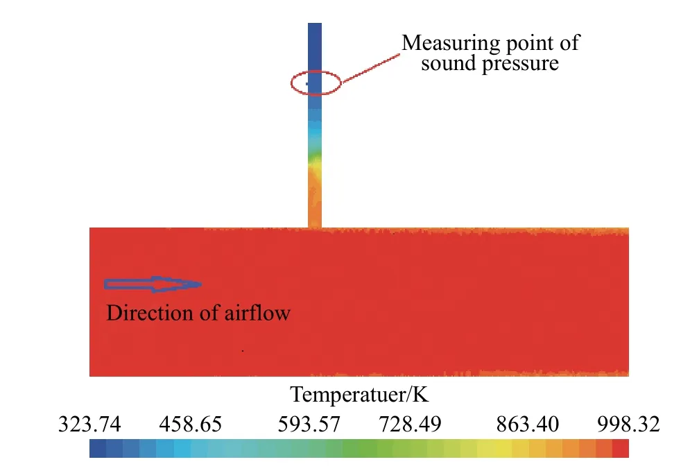
Fig. 11 Temperature cloud diagram of support
3.2 Analysis of sound field
In order to explore the influence of the extracted sound measurement method on the sound field in the measured pipe. The sound pressure at the same position is compared between using the high temperature sensor support and the directly embedded sensor in the test pipe. The results are shown in Fig.12.
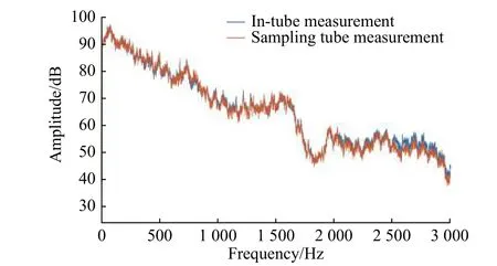
Fig. 12 Sound pressure signals measured by using the high temperature sensor support and the sensor directly embedded in the test pipe
Fig.12 shows that the sound pressure level measured by the sensor directly embedded in the test pipe with the high temperature sensor support are consistent with the fluctuation of the sound pressure level. The curves of the middle and low frequency bands almost coincide, and the error is less than 0.5 dB. However, the error of the high frequency band is slightly larger. The main reason for this phenomenon is that the connection between the waveguide and the hose is not absolutely smooth, and some sound waves are reflected back, resulting in inaccurate test results. For studying the intake/exhaust muffler,the low and medium frequency bands are the main frequency bands. The high temperature sensor support therefore meets the measurement requirements.
4 Experimental Evaluation
High-temperature and high-speed airflow conditions were simulated on the high-temperature high-speed test rig constructed in this study.The noise signal is corrected by the combined sound source as the excitation source, using the two-load method to test the transmission loss of the muffler under high temperature and highspeed airflow conditions[17]. The test equipment required for the test is shown in Tab.2, and an image of the test bench is shown in Fig.13.

Tab. 2 Equipment required for testing
5 Discussion
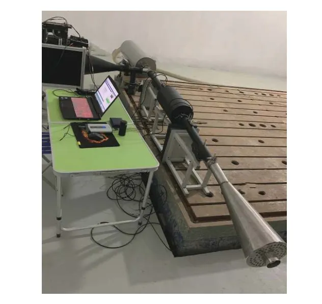
Fig. 13 Transmission loss test of muffler under high temperature and high-speed airflow conditions
The two load methods are used to simulate and test the transmission loss of the muffler under high-temperature and high-speed airflow conditions. The airflow velocity and temperature were set as 20 m/s and 400 K respectively, and both the simulation result and the experimental result were shown in Fig.14.
Fig.14 shows that the overall trend of the transmission loss curve obtained by the simulation and experiment is consistent, which proves that the test bench can effectively simulate the working conditions of high temperature and highspeed airflow, furthermore performed as the transmission loss test for mufflers in high temperature and high-speed airflow environments.However, due to the actual working conditions,the airflow in the pipeline will generate aerodynamic noise, resulting in a low signal-to-noise ratio in the pipeline, which makes the actual measured transmission loss curve fluctuate greatly.
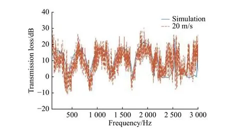
Fig. 14 Results of simulation and experimental of the transmission loss under high temperature and high speed airflow conditions
6 Conclusions
Based on the general theory for measuring transmission loss in mufflers, a high-speed and high-speed airflow simulation measuring device for muffler was built, and the following conclusions were drawn:
① Use of the high-speed fan and highpower/high-speed airflow heating device will effectively simulate the real working environment of the muffler under high temperature and highspeed airflow.
② A high temperature sensor support is designed to measure the sound pressure in the pipeline by means of an extraction measurement,perform the measurement of high pitched sounds by ordinary sensors, and reduce the cost of testing.
③ Change the end load of the test pipe quickly through the use of a variable load to ensure the consistency before and after test environment.
④ The noise signal, provided to the test bench by the combined sound source system, is modified according to the pipeline transfer matrix, which realizes the noise signal output with stable high pressure levels in a wide range of test frequencies.
 Journal of Beijing Institute of Technology2020年2期
- Journal of Beijing Institute of Technology的其它文章
- Anisotropic Total Variation Regularization Based NAS-RIF Blind Restoration Method for OCT Image
- 2D Augmented Coprime Array Geometry Based on the Difference and Sum Coarray Concept
- Design of a 70 MPa Two-Way Proportional Cartridge Valve for Large-Size Hydraulic Forging Press
- Object Recognition Algorithm Based on an Improved Convolutional Neural Network
- Research of Current Mode Atomic Force Microscopy (C-AFM) for Si/SiC Heterostructures on 6H-SiC(0001)
- Experimental and Numerical Study on the Gas Explosion in Urban Regulator Station
