Numerical simulation of the effect of waves on cavity dynamics for oblique water entry of a cylinder *
Gui-yong Zhang , Zhao Hou Tie-zhi Sun Hai-peng Wei, Ning Li, Bo Zhou , Ying-jie Gao
1. School of Naval Architecture, Liaoning Engineering Laboratory for Deep-Sea Floating Structures, Dalian University of Technology, Dalian 116024, China
2. State Key Laboratory of Structural Analysis for Industrial Equipment, Dalian University of Technology, Dalian 116024, China
3. Collaborative Innovation Center for Advanced Ship and Deep-Sea Exploration, Shanghai 200240, China
4. Beijing Institute of Astronautical Systems Engineering, Beijing 100076, China
5. Marine Design and Research Institute of China, Shanghai 200011, China
Abstract: The water entry process associated with complicated unsteady structures, with consideration of the influence of the waves,is not well studied. In the present work, the oblique water entry of a cylinder under different regular waves is numerically investigated. The volume of fluid (VOF) method and the sub-grid scale (SGS) stress model based on the large eddy simulation (LES)method are adopted for the 3-D simulation with six degrees of freedom. The present numerical model is based on a wave model, and as shown by the previous work that the predicted cavity evolution in the calm water agrees well with the experimental results. The present model is validated and it is shown that it could be used to predict the correct wave periods and fluctuations. The cavity evolution mechanism, the dynamic characteristics and the vortex structures are analyzed. The cavity of the water entry with waves closes more quickly than in the calm water case. Finally, several parametric studies of the water entry with different wave heights and water entry locations are carried out. The results provide insights into the effects of the waves on the cavity dynamics for oblique water entry problems.
Key words: Large eddy simulation (LES), wave, oblique water entry, cavity dynamics
Introduction
The water entry process involves the impacts of a structure on the water surface and then its entering into the water through the air, with cavity formation,closure and collapse. It is a nonlinear and unsteady process involving multiphase flows and complex vortex structures, and is an important issue in various fields, such as the water entry and exit of ship bows,torpedo launching, and unmanned underwater vehicle(UUV) airdropping[1-3]. However, the great impact force, the cavity formation and collapse during the process of the water entry always lead to problems,including the instable trajectory, the structure damage and vibration. So, this issue becomes a research focus for decades.
The earliest experiments were carried out by Worthington et al.[4]with recorded cavity evolutions in the vertical water entry of different structures.Enriquez et al.[5]conducted water entry experiments of disks to investigate the characteristics of the cavity collapse and pinch-off. Many experiments were performed, focusing on the water entry of different objects under different working conditions[6]. Sun et al.[7-8]studied the cavity dynamics and the splash crown behaviors under the influence of a viscous liquid by a series of experiments. Although the experiment can provide some valuable information about the water entry phenomena for a qualitative analysis, the dynamic measurements and the internal flow structures are difficult to obtain. As a consequence, the theory of the water entry becomes one of the most interesting fields for researchers. The first formulas for the water entry impact load of a wedge were obtained by von Karman[9]in order to predict the maximum pressure of seaplane floats during landing, using the momentum theorem and the additional mass method. Subsequently, one sees more and more theoretical studies of water entry, including Wagner[10], Aristoff and Bush[11], and these results play significant roles in understanding the mechanism of the water entry. Zhang et al.[12]studied the effects of the Froude number and the geometry on the water entry of a 2-D ellipse. They found that the peak pressure position first appears at the spray root, and then shifts to the bottom of the ellipse after a critical time. However, these methods are more often than not based on some idealized hypotheses and simplifications, and the results can not very effectively describe the water entry events involving unsteady multiphase flows.
To deal with strongly nonlinear and unsteady problems, numerical approaches gradually become an important choice. Gaudet[13]investigated the water entry of circular disks with low Froude numbers and analyzed the dynamic characteristics of the cavity,with results in good agreements with both analytical and experimental results. Based on the incompressible fluid assumptions with the boundary-element formulation and the nonlinearities to be considered in the free surface, Battistin and Iafrati[14]focused on the water entry of symmetric and axisymmetric structures of arbitrary shape in terms of the pressure distributions and the total hydrodynamic load features.Ma et al.[15]conducted a two-phase smoothed particle hydrodynamic (SPH) simulation of the vertical water entry of a 2-D structure. They proposed a new local boundary treatment method in the framework of the coupling boundary method. .Due to the high Reynold number, the influence of the turbulence should be considered. Currently, most computational studies are based on the Reynolds-averaged Navier-Stokes(RANS) method[16], which could capture large scale eddies with a small time step and a very fine grid.While the large eddy simulation (LES) method is expected to give better prediction for turbulent eddies,details of the cavity, and unsteady flows[17-18]. Yu et al.[19]adopted the LES method to analyze the mechanism of the cloud cavity shedding around an axisymmetric projectile and these results were compared with experimental ones. Using the LES approach, Li et al.[20]focused on instantaneous cavity flows of a cylinder and a hydrofoil, including the features of the cavity evolution, the pressure fluctuations, the velocity, and the drag and lift coefficients. Using the LES, Wang et al.[21]studied the unsteady characteristics, such as the cavity, the re-entry jet, the velocity and the pressure, of cloud cavitating flows around an axisymmetric projectile. In the present work, the LES model is used for a high quality prediction of multiphase flows, especially the vortex structures and the cavity evolution.
The wave as a regular phenomenon in the ocean engineering field, really makes a great difference for the dynamic characteristics, along with many very complex problems. Many attempts were made to conduct experiments and simulations as close as possible to the reality, with the influence of the waves considered. Wan et al.[22]experimentally investigated the water entry and exit process of a conceptual energy-converter in regular waves, and a blended station-keeping potential-flow solver was used to study the strongly nonlinear phenomena and dynamic structures of the water entry and exit with waves numerically. Mas-Soler et al.[23]focused on the dynamic characteristics of a semi-submersible platform with wave spectra. With consideration of the influence of the waves, Hu and Liu[24]simulated the water entry process of a flatted-bottom body and obtained the time histories of the maximum pressure on the bottom at different initial velocities.
The problems of the water entry without waves were widely studied, mostly focusing on the characteristics of the pressure and the displacement of the vertical water entry. The present study is a continuation of our previous work[25], with numerical simulations of the oblique water entry at a low Froude number under the influence of the waves, using the LES approach, the volume of fluid (VOF) method and the Eulerian multiphase model. An overlap grid of 6DOF is used to capture the large displacement of the cylinder. The first order wave model is used to predict the effects of the waves. Subsequently, the cavity evolution mechanism, the flow pattern and the parametric studies for different wave heights and water entry locations, are analyzed. Parts of the preliminary validation studies of this numerical model were presented in our precious paper.
1. Numerical methodology
1.1 Governing equations and LES model
In the present study, the homogeneous and incompressible flow hypothesis are adopted because of the low entry speed and room temperature conditions. The original forms of the mass and momentum conservation equations are:

where ρ is the fluid density, t is the time, p is the pressure, ν is the kinematic viscosity and uiand xiare the velocity component and the position along the x, y, z directions, respectively.
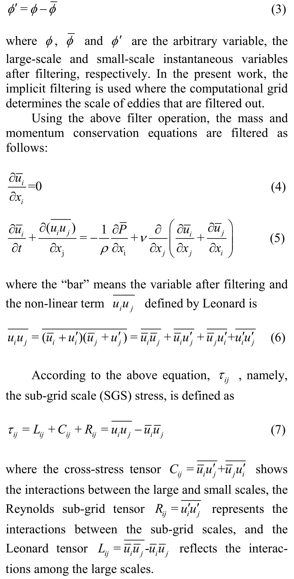
In the LES approach, large eddies are solved directly, while small eddies are modeled. These different scale eddies are identified by filtering original Navier-Stokes equations in the physical space
1.2 Sub-grid scale stress model
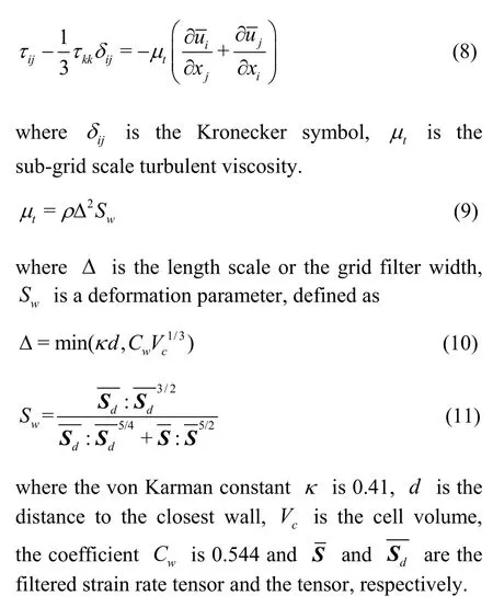
In the present work, the wall-adapting local eddy-viscosity (WALE) model[26]is used because it is less sensitive to the parameter than other models.Moreover, this model can automatically determine the accurate scaling at the walls so that the near-wall damping is not required. Then, the SGS stress is described by the Boussinesq hypothesis as
1.3 VOF model
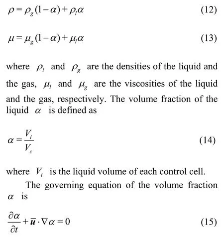
The VOF model is used to capture the free surface in this paper. This model describes different fluids by the volume fraction of each phase and assumes that all immiscible fluids share the velocity and pressure fields. Then, the two-phase flow can be treated as two single-phase ones in the governing equations, separately. In the VOF approach, the fluid density and the dynamic viscosity are defined as:
1.4 Boundary conditions and mesh generation
The present work is carried out using the commercial computational fluid dynamics (CFD)software STAR-CCM+ 12.02.010. In this software,the VOF wave model (a physical model in STAR-CCM+) is used to simulate different waves moving from left to right as shown in Fig. 1. Overlap grid and 6DOF body are adopted to simulate the process of the water entry. The setting of the boundary conditions is shown in Fig. 1. Meanwhile, the overset mesh is used for the boundary of the overlap grid, as shown in Fig. 2.F
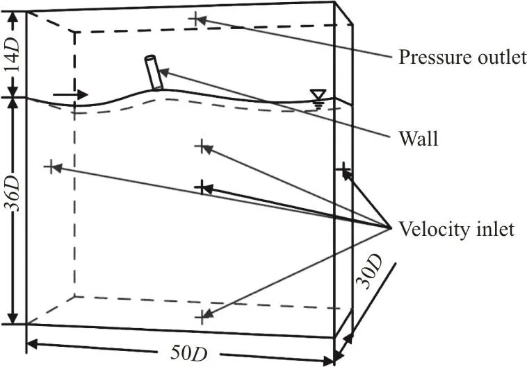
ig. 1 The computational domain

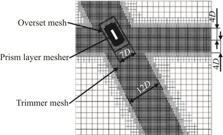
Fig. 2 The computational mesh on a plane section (D is the diameter of cylinder)
To verify the mesh convergence, four different numbers of grids, including the very coarse one(3.2×10⁶), the coarse one(6.2×10⁶), the medium one(9.2×10⁶), and the fine one(12.2×10⁶), are used in a grid convergence study. Figure 3 represents the power spectrum density at the monitor point on the wave surface. It can be seen that the slope of the medium grid is close to -5/3, which indicates that this scale of mesh approaches the convergence. Hence, in order to balance the computational cost and the accuracy in the present work, the medium grid is chosen in following analyses.
1.5 Wave model and numerical method validation
A good understanding of the first order wave is essential in the analysis of the cavity evolution and the vortex structures because high order waves are non-linear superpositions of the first-order ones[27].Karim et al.[28]investigated the influence of the first-order waves on the free falling lifeboat. On the basis of the first order wave, Hu et al.[24]analyzed the hydrodynamic forces on a flatted-bottom seafloor mining tool. So, in the present work, the first order wave model is used. based on the Stokes theory of the wave. This wave model reflects the characteristics of the Stokes wave that the wave peak is steep and the valley is correspondingly flat. Besides, with the first order wave, it is easy to find the wave peak, the wave node and the wave valley with a high accuracy for further parametric studies.
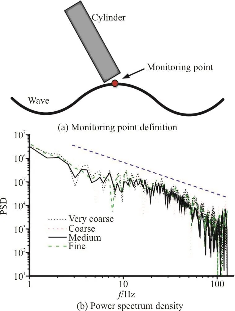
Fig. 3 (Color online) Power spectrum density at the monitor point on the wave surface with four different grid levels
The equation for the surface elevation is
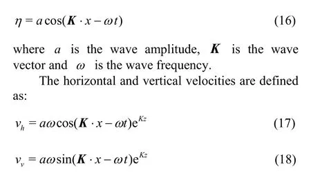
where z is the vertical distance from the mean water level.
The wave model and the numerical method are validated with a deep water approximation. When this option is activated, the dispersion relation for the waves is independent of the water depth (see Eq. (19)).When this option is deactivated, Eq. (20) applies. The dispersion relation (between the wave period T and the wave length) for the first order waves in a finite water depth d is:

In our previous work[26], the model for the water entry in the calm water was initially validated. Both qualitative and quantitative variables, including the cavity evolution, the angular displacement θ, which represents the angle between the axis of the cylinder and the water surface, the velocity v and the acceleration a of the cylinder, including both the horizontal and vertical components, are basically in agreement with the experiment. Therefore, the numerical model could satisfy the requirements of numerical stability and accuracy.

Fig. 4 (Color online) Wave amplitudes at different positions: (a)0.5 m, (b) 2.0 m to the left boundary with wave height H=0.10m , where the subscript of η means the distance to the left boundary
2. Results and discussions
2.1 Comparisons of water entry between the cases of with waves and in calm water

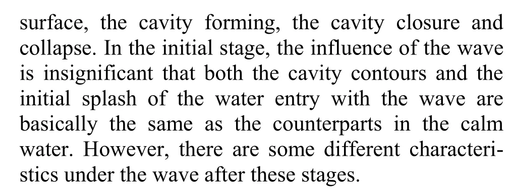
Obviously, the cavity surface generated by the water entry with waves is not so smooth like entering into the calm water, because the wave continuously transfers the kinetic energy to the surrounding fluid and disturbs the movement of the fluid, leading to a complex flow field. The cavity surface is impacted by the fluid from different directions so that the surface is no longer smooth. Besides, because the wave propagates in x direction and makes the initial splash move along x direction, this splash of the water entry with the wave is not as intense as that in the calm water.And the evolution of the cavity with the wave has a longer period. Because the wave transfers the kinetic energy to the surrounding fluid and the fluid moves upward and outward, the cavity continually develops and the cavity closure is delayed. Similarly, the wave delays the appearance of the re-entrant jet (with a height lower than that in the calm water) and the secondary splash.

Fig. 5 (a) The front view of water entry with waves, (b) The top view of water entry with waves of cavity evolution at typical moments (the wave height is H =0.10m , wave length is λ=0.90m and water entry location is the wave peak)
And then the time histories of variables in the calm water and in the case with the wave are obtained as shown in Fig. 6. All variables vary similarly. In the pressure, velocity and acceleration curves, the fluctuations remain during the period of the cavity closure. So, it can be seen that the cavity of the water entry with the wave closes later than that in the calm water. In the initial stage of the water entry, the angular displacements under both two conditions are correspondingly the same, because, the inertia forces,as compared with the influence of the wave, are still large enough and dominant during this period. While with the decline of the velocity, the effect of the wave becomes prevailing. Thanks to the wave propagation,the impact of the cylinder entering into the wave is smaller than in the calm water so that the peak of the acceleration is smaller, the pressure and the velocity are larger than those in the calm water. With the increase of the water entry depth, the wave weakens,that means that the tail of the cylinder experiences the greater impact from the wave than the head of the cylinder. So, the cylinder entering into the wave rotates quickly and the angular displacement grows fast.
To further analyze the difference of the unsteady vortex structures under these two conditions, the second invariant Q of the velocity gradient tensor is used (as proposed by Hunt et al.[29]):


Fig. 6 (Color online) Comparisons of (a) Pressure at the center point of the cylinder’s head, (b) Velocity, (c) Acceleration, (d) Angular displacement of the cylinder entering into calm water[26] and wave (wave height H=0.10m, wave length λ=0.90m and water entry location at wave peak)

Fig. 7 Vortex structures of Q iso-surface (Q =105s-2) at typical moments for the case with the wave height H =0.10m,wave length λ=0.90m and water entry location at wave peak
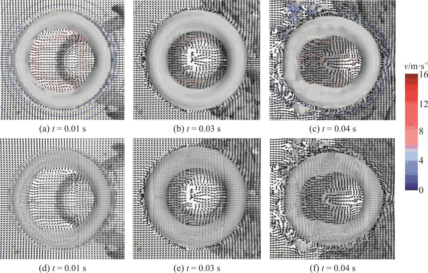
Fig. 8 (Color online) Vortex ring in the middle section combined with Q iso-surface (Q=105s-2) and velocity distribution at typical moments for the case with the wave height H =0.10m, wave length λ=0.90m and water entry location at wave peak
And the vortex ring generated by the water entry with the wave stays longer and becomes more complex than that in the calm water. Firstly, it is because for the cavity formed by the water entry with the wave, it takes a longer time from the impact on the water surface to the cavity closure so that the influence of the cavity takes its effect later, which makes the vortex ring disappear later. Secondly, it is because the initial splash of the water entry with the wave is not so intense as in the calm water, which reduces the impact force on the vortex ring and then it stays longer. At 0.01 s, 0.03 s, a clear vortex ring caused by the high velocity gradient at the tail can be observed, and it is symmetric in both horizontal and vertical directions. While at 0.04 s, the flow field becomes more complex and the vortex ring is no longer symmetric, not like that in the calm water.Besides, the flow field inside the vortex ring generated by the water entry in the calm water is complex, but the flow field outside it is simple, while in the case with the wave, opposite phenomena are observed, one sees a simple internal flow field of the vortex ring and a complex outside flow field, because the propagation of the wave makes the left side fluid move to the right side and the fluid impacts the vortex ring, resulting in a complex flow field. And there are many vortices around the vortex ring in the case of with the wave.
2.2 The influence of wave heights
As shown in Table 1, three different wave heights are chosen to study the effect of the wave height on the water entry process. With the increase of the wave height, the wave steepness H/λ increases,which means a steeper wave peak and a stronger influence of the wave because in this part, the water entry location is at the wave peak. So, the larger wave height reflects the greater impact force of the cylinder.
Figure 9 shows the cavity contours under three conditions listed in Table 1. It is found that the greater the wave height is, the earlier the cavity closes and the farther away the closed point is from the cylinder’s tail, which means a smaller volume of the closed cavity. As the cylinder enters into the water, the wave with a greater wave height means a greater impact on the cavity, which accelerates the cavity closure.Besides, a greater wave height also means a larger volume of the falling cavity.
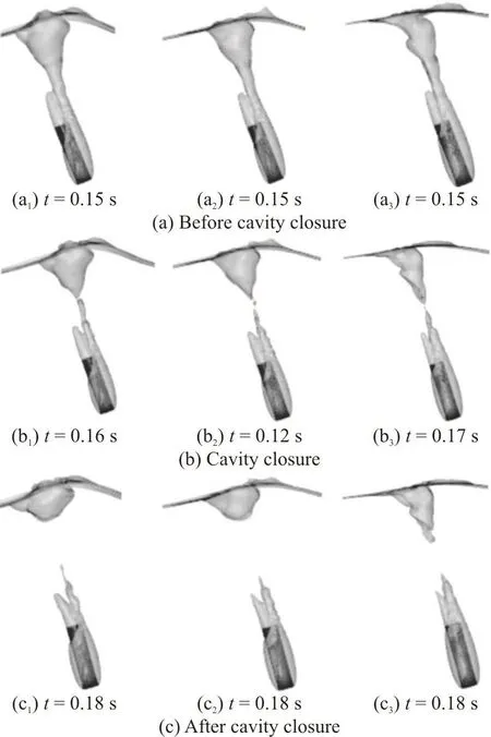
Fig. 9 Contours of cavity under condition 1 (left), condition 2(middle) and condition 3 (right) at typical moments
Figure 10 shows some typical variables to reflect the effects of the wave height on the oblique water entry. Overally, the variables in cases of different wave lengths vary in similar manners. In the initial stage of the water entry, the velocities and the angular displacements for different wave heights are basically the same. During this period, due to the great instantaneous impact force, the acceleration and the pressure reach their peak values. A greater wave height means a steeper wave peak. Although the contact area between the cylinder and the water surface in the case of a larger wave height is not very large at the beginning, the wave promotes the movement of the cylinder and the stressed area of the water entry in that case increases significantly. So, a greater wave height leads to a lower pressure peak and a lower acceleration peak while these peaks appear at the same time. After the initial stage of the impact, the pressure, the acceleration and the velocity are essentially similar for different wave heights. As for the angular displacement, the greater the wave height is, the smaller the angular displacement will be.During this stage, the wave influenced area is on the left side of the cylinder’s head and for a larger wave height, we have a larger influenced area with this area closer to a centroid. So, the moment of the cylinder entering into the wave with a larger wave height is smaller than that with a smaller wave height and the moment is related with the deflection of the cylinder.During the stage of the cavity closure, the curves of the acceleration see a great difference due to the pinch-off cavity. The fluctuation of the acceleration with a larger wave height occurs earlier because of the earlier cavity closure. After the cavity closure, the influence of the wave height on the hydrodynamic characteristics is more significant than before. During this period, the whole cylinder is impacted by the wave and a greater wave steepness reflects a greater impact force of the cylinder. So, when the wave height is greater, the acceleration and the angular displacementare larger and the decline of the velocity is greater.After 0.3 s, the wave gradually weakens and the gravity becomes more and more important. When the gravity of the left side cavity is dominant over the rotating force, the cylinder will rotate in the anticlockwise direction (referring to the condition with the wave height of 0.05 m) and otherwise, it will continue to rotate in the clockwise direction(referring to the condition with the wave height of 0.10 m).

Table 1 Three water entry conditions with different wave heights

Fig. 10 (Color online) Time histories of (a) Pressure at the center point of the cylinder’s head, (b) Acceleration, (c)Velocity and (d) Angular displacement of the cylinder with different wave heights (as shown in Table 1)
2.3 The influence of water entry locations
All above results are based on the water entry at the wave peak. In this section, the influence of the water entry location is analyzed by using three different typical positions as shown in Table 2. The waves used are the first order wave, but they have the characteristics of the Stokes wave as described in the previous section. So, the wave peak is steep and the wave valley is correspondingly flat.
As for the water entry at the wave valley, in the initial stage of the impact, the contact area between the cylinder and the water surface is larger than those under other two conditions so that the impact on the cylinder is greater. During the later period of the water entry, because the wave propagates from the left side to the right side, the higher wave surface continually impacts the cylinder. The cylinder entering into the water at the wave node has a smaller contact area than under other conditions because the wave propagates in x direction and the cylinder is oblique so that the right side of the cylinder’s head does not contact the water.So, the impact on the cylinder is smaller. As the cylinder enters into the water, the wave propagates from left to right and the influence of the wave becomes significant. With regard to the water entry at the wave peak, in the initial stage of the water entry,the contact area is larger than that of the water entry at the wave node and is smaller than that of the water entry at the wave valley. With the increase of the water entry depth, because the left side wave is not so high and the water only slightly impacts the cylinder,the influence of the wave is weaker than under other conditions.
As shown in Fig. 11, the cavity evolution is significantly influenced by the water entry location.The cylinder in the case of the water entry at the wave valley is impacted more severely and the wave effects are more significant than under other conditions so that the wave impacts the cavity to make it collapse sooner. As a consequence, the cavity generated by the water entry at the wave valley takes the shortest time from the impact of the water surface to the cavity closure (0.09 s) among the times taken under these three conditions, and it is half of the closing time under the condition of the water entry at the wave peak. When the cylinder enters into the water at the wave node, a larger area of the cylinder is impacted by the wave than that in the case of the water entry at the wave peak, which impedes the development of thecavity. So, the cavity closure in the case of the water entry at the wave node is earlier than that in the case of the water entry at the wave peak. Besides, the peak entry involves the largest volume of the falling cavity and the closed cavity, while the case of the trough entry involves the smallest volume. That is influenced by the different impact forces and contact areas as described above.

Table 2 Three water entry conditions with different water entry locations
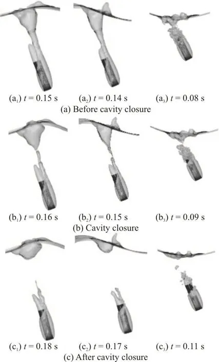
Fig. 11 Contours of cavity under condition 4 (left), condition 5(middle) and condition 6 (right) at typical moments
The variables in Fig. 12 see similar tendencies with some differences at the beginning and during the period of the cavity closure. In the initial stage, the pressure, the acceleration and the angular displacement are greatly influenced by the water entry locations unlike the velocity. However, the pressure and acceleration peaks in the case of the water entry at the wave valley are different from those under other two conditions. Because when the cylinder enters into the water at the wave valley, the contact area is larger and the wave effects are more significant than others, the peaks occur earlier and the decline of the velocity is greater. The contact area in the case of the water entry at the wave peak is not so large as that in the case of the wave valley entry but larger than that in the case of the wave node entry, and the influence of the wave under this condition is not so significant. So, the peaks in the case of the water entry at the wave peak occur later than those in the case of the wave valley entry but earlier than those in the case of the wave node entry. Besides, the magnitudes of the pressure and the acceleration in the case of the water entry at the wave valley have sharper peaks than others, followed by the case of the wave peak entry and the case of the wave node entry sees the smallest peaks. Besides, the angular displacements in the cases of the water entry at the wave valley and at the wave node are basically the same and are larger than those in the case of the wave peak entry, because the impact from the wave makes the moment grow, leading to the deflection of the cylinder.
After the initial impact stage and before 0.09 s,except for the pressure, the acceleration and the velocity, other variables are correspondingly the same for different water entry locations. Because of the impact of the wave in the initial stage, the magnitudes of the pressure and the acceleration in the case of the water entry at the wave node are greater than those in the case of the wave peak entry but smaller than those in the case of the wave valley entry. Above characteristics of the pressure and acceleration curves affect the velocity under the condition of the wave valley entry and the wave node entry, make it falling faster and becoming lower than that in the case the wave peak entry. After 0.88 s, the cavity generated by the water entry at the wave valley closes earlier than under other conditions. The tail of the cavity pinches off and the drag force of the cylinder decreases greatly so that the cylinder deflects significantly and the angular displacement grows faster than under other conditions. While the volume of the pinch-off cavity is not so great, so the curves of the velocity and the acceleration under the condition of the wave valley entry do not see much fluctuations. Besides, the velocity under the condition of the wave valley entry drops linearly. Around 0.15 s, the cavities under other two conditions close and the volumes of the pinch-off cavities are great so that one sees distinct fluctuations in the curves of the velocity and the acceleration.After 0.16 s, with the increase of the water entry depth,the pressure, the acceleration and the velocity under the three conditions are basically the same.
3. Conclusions
In the present work, the unsteady characteristics of the oblique water entry with waves are studied with 3-D numerical simulations, where the LES and the first order wave method are used to predict the multiphase flow events. Main findings of the present work can be summarized as follows:
(1) The cavity evolution with the wave can be divided into four stages: impacting the water surface,forming the cavity, the cavity closure and the cavity collapse. But the wave makes a great difference to the cavity. The cylinder entering into the wave takes a longer time from impacting the water surface to the cavity closure than in the calm water.
(2) The vortex generated by the water entry with the wave is also related with the unsteady characteristics and the cavity evolution as in the calm water case. However, the vortex ring generated by the water entry with the wave stays for longer time than in the calm water case and is no longer symmetric before it disappears. Besides, many small vortices are observed around the vortex ring under the wave condition.
(3) Parametric studies of the water entry for different wave heights and water entry locations show that variables vary in similar trends and always see fluctuations around the period of the cavity closure.The larger the wave height is, the more quickly the cavity closes. Furthermore, the water entry at the wave valley severely influences the wave and takes a shorter time from impacting the water surface to the cavity closure.
This paper is focused on the water entry problem with the first-order wave as it is the basis of many waves. In order to analyze the water entry events under the conditions closer to the real situations,further analysis of the water entry in irregular waves such as the second-order Stokes wave and the fifth-order Stokes wave will be investigated in the future.
Acknowledgments
This work was suppored by the China Postdoctoral Science Foundation (Grant No.2019T120211), the Natural Science Foundation of Liaoning Province (Grant No. 2020MS106), the Liaoning Revitalization Talents Program (Grant No.XLYC1908027), the Fundamental Research Funds for the Central Universities (Grant Nos. DUT20TD108,DUT20LAB308) and the Supercomputing Center of Dalian University of Technology.
- 水动力学研究与进展 B辑的其它文章
- The effects of caudal fin deformation on the hydrodynamics of thunniform swimming under self-propulsion *
- Control of water contamination on side window of road vehicles by A-pillar section parameter optimization *
- Reduction of wave impact on seashore as well as seawall by floating structure and bottom topography *
- Applying physics informed neural network for flow data assimilation *
- Experimental analysis of tip vortex cavitation mitigation by controlled surface roughness *
- Numerical simulations of propeller cavitation flows based on OpenFOAM *

