
Janus few layered graphene with asymmetric wettability as anti-flooding cathode supports in proton exchange membrane fuel cells
2020-01-03 15:18:36JingLiuXiokeLiXiojinLiLuhuJing
Jing Liu ,Xioke Li ,Xiojin Li ,Luhu Jing,∗
a College of Materials Science and Engineering,Qingdao University of Science and Technology,53 Zhengzhou Road,Qingdao,Shandong,266042,China
b Qingdao Institute of Bioenergy and Bioprocess Technology,Chinese Academy of Sciences,Qingdao,Shandong,266101,China
ABSTRACT Water balance in cathode catalyst layer (CCL) is crucial for proton exchange membrane fuel cells(PEMFCs).Herein,we report a novel strategy to develop a Janus few layered graphene particles (FLGP) with asymmetric wettability by varying the carbon precursors in the chemical vapor deposition (CVD) process.Using the Janus FLGP supported Pt with asymmetric wettability as the cathode of a PEMFC,a peak power density of 632 mW cm−2 was achieved,which was about two-folds of the hydrophobic FLGP and three-folds of hydrophilic FLGP based cathode,respectively.The enhanced performance could be ascribed to the well-constructed three-phase boundary in an anti-flooding cathode,leading to enlarged electrochemical active surface area and facilitated mass transfer.This work may provide new clues for improving water management in PEMFCs.
Keywords:Proton exchange membrane fuel cell Anti-flooding Few layered graphene Support Cathode
1.Introduction
Proton exchange membrane fuel cells(PEMFCs)hold great promises as a new generation of clean energy due to its merits of high energy density,low noise and environmental-benign [1].The performance of PEMFC is significantly affected by the water balance in the cathode.From one side,the ionic conductivity of the Nafion membrane and the Nafion ionomer in catalyst layers is highly dependent on the hydration.Inadequate humidity could result to high ohmic resistance of membranes,and even local hotspots leading to membrane failure.From the other side,the cathode would be in high risk being flooded in case of the excessive water,generated by the cathodic oxygen reduction reaction and that electro-osmatic dragged from the anode,being left in electrodes [2-4].Therefore,it is essential to keep the water balance in cathodes to meet the criteria of membrane hydration and avoid a flooded cathode.
In the past decades,the importance of cathode catalyst layer (CCL)to prevent cathode flooding has attracted much attention and been extensively studied [5-10].Jiao and Zhou numerically simulated and showed that the hydrophobicity of the electrode must be carefully controlled,and the catalyst layer is expected to be more or similarly hydrophobic comparing to the gas diffusion layer (GDL),so that liquid water could be expelled monotonously from catalyst layer to GDL[11].As known,in cathodes,it involves gaseous oxygen reacting with hydrated protons,together with electrons,to generate liquid water,which occurs on catalyst surface.So a well-constructed triple phase (solid/liquid/gas) boundary (TPB) is expected to facilitate the reaction.With the aim to tune the hydrophobicity of the CCL,a general strategy is to introduce hydrophobic additives,such as polytetrafluoroethylene(PTFE),silicone oil and polydimethylsiloxane etc.,to modify the CCL[12-16].However,the introduction of nonconductive polymers unavoidably covers some active sites and thus decreases the electrochemical surface area (ECSA) of the Pt catalyst.It is a dilemma to mediate the hydrophilic surface for proton conductivity and the hydrophobic surface for oxygen gas transport without any loss in active sites.It was reported that employing oxygenophilic and hydrophobic ionic liquids to modify the surface of nanocarbon by forming a waterequilibrated secondary medium between solid catalyst and liquid electrolyte.Qiao et al.generated more favorable triple-phase contact points around the active sites [17].Despite great efforts have been devoted in addressing the above dilemma between proton transfer and oxygen transport,it is still a great challenge to achieve water balance without introduction of foreign additives.
Janus materials with different wetting properties on opposite sides have attracted global interests for their potential applications in membrane distillation,oil-water separation,water collection and sensors [18,19].Inspired by this a Janus few layered graphene with biphilicity as the catalyst support is designed.Specifically,the outer wall of graphene is hydrophobic,which facilities expelling water generated and provides the pathway for oxygen diffusion,while the inner wall of the graphene is hydrophilic which could provide the pathway for proton.
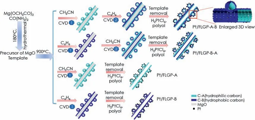
Fig.1.Illustration of the preparation route of Pt/FLGP samples.
2.Experimental
2.1.Catalyst preparation
Firstly,Mg2(OH)2CO3was prepared,which is used as the precursor for template and catalyst for few layered graphene particles (FLGP).6.44 g of Mg(OCH3CO)24H2O dissolved in 75 mL of water and 1.2 g of urea in 25 mL of water were mixed and magnetically stirred for 30 min.Afterwards,the above solution was transferred to a Teflon-lined autoclave,then kept at 180 °C for 2 h.Finally,white precipitate was collected by filtration and dried in an air oven at 100 °C.
FLGP with tuned wettability were synthesized via the chemical vapor deposition(CVD)process.The obtained Mg2(OH)2CO3in a quartz boat was placed in the center of the tube furnace with a gas flow of Ar(1000 ml min−1)and heated to 450°C and maintained for 2 h.During this process,Mg2(OH)2CO3could decompose into MgO that is known the catalyst and the template for the formation of graphene[20-23].After that the furnace was heated to 900°C,and another Ar steam flowing through a flask of acetonitrile at room temperature was introduced to the reactor for 10 min.Subsequently,the Ar steam was switched to flow through benzene for 5 min.Then,the tube furnace was cooled down to room temperature naturally.The as-formed samples in the quartz boat were collected and treated with 1Mhydrochloric acid for 8 h in the ambient to remove the template.The mixture was filtrated and washed by copious of deionized water,which was then dried in an oven at 100°C overnight.The obtained black powder was denoted as FLGP-A-B.For comparison,the sample obtained by changing the sequence of the flowing gas,i.e.,first through benzene and then acetonitrile,was denoted as FLGP-B-A.The sample prepared only by Ar flowing through acetonitrile or benzene were denoted as FLGP-A and FLGP-B,respectively.
The FLGP samples were used as the support for depositing Pt nanoparticles.The Pt colloid was synthesized by the polyol method [24].In brief,a required amount of hexahydrated chloroplatinic acid(H2PtCl6·6H2O) was added to ethylene glycol (EG) under stirring to obtain bright yellow solution with a concentration of 0.05 mg Pt4+/mL EG.The pH value of the solution was then adjusted to 13 by adding sodium hydroxide.The mixture was kept at 130°C for 3 h to yield dark brown Pt colloids.After the Pt colloids cooling down to room temperature,a required amount of FLGP support was added.The obtained precipitate was filtered,washed and dried in a vacuum oven at 75°C for 8 h.The obtained sample was denoted as Pt/FLGP-A-B,Pt/FLGP-B-A,Pt/FLGP-A and Pt/FLGP-B.The mass loading of Pt in the catalyst is determined to be around 30 wt%by thermogravimetric analysis (TGA)in Fig.S1.
2.2.Physicochemical characterization
Powder X-ray diffraction(XRD)was performed on a Rigaku Miniflex II diffractometer with Cu Kα radiation at 40 kV.The morphology of the samples was characterized by scanning electronic microscopy (SEM,JSM-7800F) and transmission electron microscopy (TEM,FEI,Tecnai G2F30).TGA was conducted on an SDT Q600 thermoanalyzer under air.Contact angle was measured on LAUDOR scientific LSA60 surface analyser.
2.3.Electrochemical characterization
The electrochemical performance of the samples was evaluated by a Pine potentiostat in a three-electrode electrochemical cell.A graphite rod was employed as a counter electrode.The reference electrode was a Ag/AgCl electrode in 0.5 M H2SO4solution.The working electrode was made by dripping the catalyst ink on a 5 mm diameter glass carbon(GC) disk to form a thin-film layer.The catalyst ink was prepared by weighting 5 mg of the samples and then dispersing in 2 mL of ethanol plus 30 μL of 5 wt% Nafion® solution (DuPont,USA) in an ultrasonic bath for 10 min.After that,20 μL of aliquots was pipetted on the GC disk and dried naturally.A stable cyclic voltammogram(CV)curve with a scan rate of 10 mV s−1was recorded after surface clean by potential scanning between −0.17-0.93 Vvs.Ag/AgCl in a nitrogen saturated 0.5 M H2SO4electrolyte.The scan rate was kept at 100 mV s−1.The electrochemical performance on the oxygen reduction reaction were performed in an oxygen saturated 0.5 M H2SO4solution at a scanning rate of 10 mV s−1.

Fig.2.TEM images of FLGP-A-B (a-c),FLGP-B-A (d-f),FLGP-A (g-i),and FLGP-B (j-l).
2.4.Sing cell fabrication and testing
The membrane electrode assemblies (MEAs) were made using the procedure as follows [25].Briefly,the catalyst ink was prepared by ultrasonically blending Pt/FLGP catalysts with a Nafion solution and ethanol for 2 h.The catalyst ink was sprayed onto the cathode side of the membrane(Nafion 212)till the Pt loading reaching to 0.4 mg cm−2.The anode catalyst layer was prepared by spraying the ink consisting of 40%Pt/C-JM with Nafion solution and ethanol.The Pt loading was kept at 0.05 mg cm−2.The MEAs were fabricated by sandwiching the catalyst-coated membranes between two prefabricated gas diffusion layer(GDL)(Torry carbon paper,10 wt%poly-tetrafluoroethylene),and then hot pressing together at 130 °C under 0.1 MPa for 1 min.The control MEAs were fabricated using 40%Pt/C-JM catalyst on both electrodes.The Pt loading in the anode and the cathode were controlled at 0.05 and 0.4 mg cm−2,respectively.The active area of the single-cell was 4 cm2.The operation temperature of the single cell was 50 °C.The anode side was fed with 100% humidified H2with a flow rate of 100 mL min−1and the cathode side was fed with 100% humidified O2with a flow rate of 200 mL min−1.
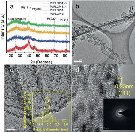
Fig.3.Physical characterization of Pt/FLGP-A-B catalyst.XRD patterns (a),TEM (b-c) and HRTEM images (d).The insert of (c) is the corresponding diameter distribution of Pt NPs.The insert of (d) is the SAED of Pt NPs.
3.Results and discussion
The wettability of the few layered graphene is dependent on the carbon precursors adopted in the CVD process.As depicted in Fig.1,Mg2(OH)2CO3was firstly synthesized via a hydrothermal method,which was then decomposed into MgO to act as the template and the catalyst for the formation of few layered graphene.Catalyzed by MgO,carbon precursors split and carbon atoms grow into graphenes[21,26,27].The hydrophilic/phobic property of the obtained carbon could be modulated by changing the carbon precursors.To obtain a hydrophilic graphene surface,acetonitrile was chosen as the precursor to generate nitrogen-doped few layered graphene catalyzed by the MgO template in the process of CVD.Subsequently,benzene was chosen as the carbon precursor to continuously form hydrophobic few layered graphene surface outside.After etching the templates,a Janus FLGP of an inner hydrophilic graphene wall (nitrogen-doped) and an outer hydrophobic graphene wall (un-doped) was obtained.Similar graphene double-tubes have been recently reported for the application in lithiumion batteries[28].It has been well demonstrated that the inner tube of the nitrogen-doped graphene is hydrophilic while the outer tube of the non-doped graphene is hydrophobic.Pt colloid was prepared by a polyol reduction method and deposited on the Janus FLGP,denoted as Pt/FLGP-A-B.For comparison,FLGP with inner hydrophobic graphene wall and outer hydrophilic graphene wall was also synthesized,and loaded Pt nanoparticles,labeled as Pt/FLGP-A-B.The merely hydrophilic or hydrophobic FLGP supported Pt nanoparticles were denoted as Pt/FLGP-A and Pt/FLGP-B,respectively.
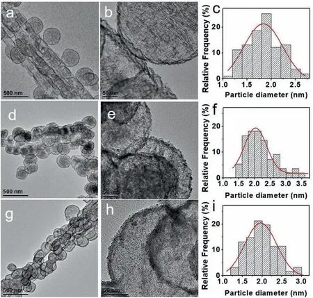
Fig.4.TEM images of Pt/FLGP-B-A (a-b),Pt/FLGP-A (d-e),Pt/FLGP-B (g-h) and the corresponding histograms of Pt particle size distribution (c,f,i).
Fig.2 shows the TEM images of the FLGP samples.For all the FLGP samples,they exhibit the similar hieratical structures of graphene nanospheres(GNPs)parasite on graphene nanotubes(GNTs).The average diameter of GNPs is around 500 nm,and the GNTs are of about 0.2 μm in width and 10 μm in length.From the enlarged TEM images,the few layered porous graphene structure of the samples could be clearly visualized.The thickness of graphene layer is about 10 nm for FLGP-A-B and FLGP-B-A,and 5 nm for FLGP-A and FLGP-B.It is reasonable that the graphene layer became thicker for FLGP-A-B and FLGP-B-A,which was experienced twice CVD processes.
The XRD patterns of the Pt/FLGP samples are presented in Fig.3a.The broad peak located at around 25° is ascribed to the graphite (002)diffraction index of FLGP,suggesting FLGP is of amorphous carbon structure.The Pt nanoparticles could be evidenced by the diffraction peak at around 40°assigned to Pt(111) planes.The TEM images of Pt/FLGP-A-B are shown in Fig.3b-d.It can be seen that the FLGP-A-B retains the hieratical nanosphere and nanotube in morphology with porous graphene layers as the scaffold,where Pt nanoparticles are distributed uniformly.The average diameter of the Pt NPs in Pt/FLGPA-B is about 1.88 nm.As shown from the HRTEM image of Pt/FLGP-A-B in Fig.3d,the interplanar distance in the Pt NP is 0.23 nm,which is attributed to the Pt (111) plane.The inset of Fig.3d exhibits the selected area electron diffraction (SAED) of Pt/FLGP-A-B,confirming the formation of face centered cubic phase of Pt.The morphology and distribution of Pt NPs in the counterpart samples are also characterized by TEM and shown in Fig.4.Pt NPs dispersed evenly on the FLGP support.The average diameter of the Pt NPs in the Pt/FLGP-B-A,Pt/FLGP-A and Pt/FLGP-B were 1.84 nm,2.03 nm and 1.97 nm,respectively.The above results suggest that the support has little influence on the dispersion of the Pt NPs,which provides a chance to study the effect of the graphene supports on the cathodic performance.
The wettability of Pt/FLGP-A-B,Pt/FLGP-B-A,Pt/FLGP-A and Pt/FLGP-B were reflected by the contact angles,as shown in Fig.5.The contact angle of Pt/FLGP-A-B and Pt/FLGP-B is 128° and 124.8°,respectively,which is much higher than that of Pt/FLGP-B-A (89.6°) and Pt/FLGP-A(91.6°).It is reasonable and expected,because for Pt/FLGPA-B and Pt/FLGP-B,the outer wall of the support is non-doped graphene,which is hydrophobic;in contrast,Pt/FLGP-B-A and Pt/FLGP-A with an outer wall ofN-doped graphene,which is hydrophilic.The relatively hydrophobic CCL is expected to avoid the water flooding of in cathode and could be able to maintain good water balance during operation of the PEMFC.
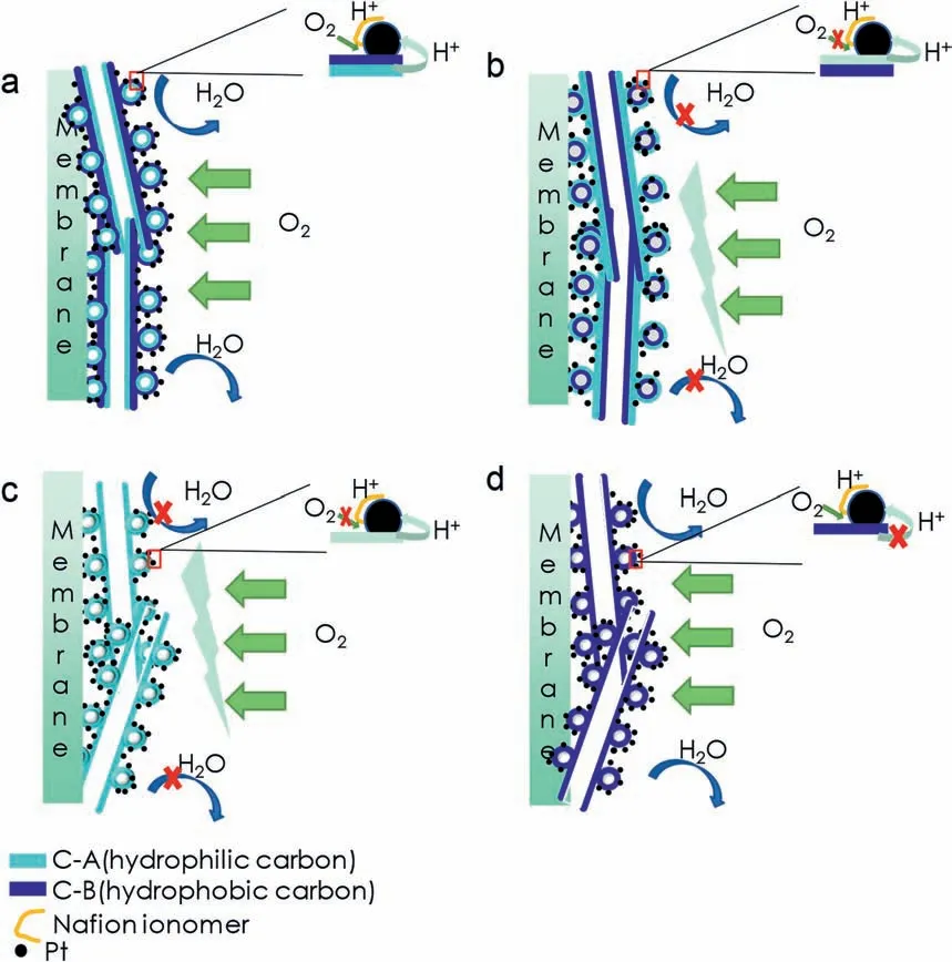
To obtain the electrochemical active surface area(ECSA)of Pt/FLGP catalyst,the cyclic voltammograms (CV) of Pt/FLGP catalysts in nitrogen-saturated 0.5 M H2SO4with a scan rate of 10 mV s−1were firstly recorded.As shown in Fig.6a,the ECSA of the Pt/FLGP catalysts were estimated from integrating the charge of hydrogen underpotential deposition area and the values are listed in Table S1.Pt/FLGP-A-B catalyst exhibited a high ECSA of 67.1 m2g−1,while the Pt/FLGP-B catalyst had the lowest ECSA of 33.1 m2g-1.The result demonstrates that biphilicity of FLGP allows the aqueous electrolyte to infiltrate the inner hydrophilic graphene surface and provides a highway for proton transfer,thus leading to the enlargement of ECSA.From the ORR polarization curves shown in Fig.6b,it can be seen that all the Pt/FLGP samples exhibit almost identical catalytic activity for the ORR in the low overpotential region (0.9-0.7 V vs.Ag/AgCl).The similar capability to initiate the ORR clearly demonstrates that the active center in the Pt/FLGP was the same in the aqueous electrolyte.However,in the massdiffusion-limiting potential region,the ORR limiting current was a little different,i.e.,Pt/FLGP-A-B and Pt/PLGP-B with the hydrophobic surface showed slight higher ORR limiting currents,as compared to the other two with the hydrophilic surface.This is probably due to the expedited oxygen transfer from the electrolyte to the hydrophobic catalyst surface across the interface.To further explore the effect of the surface characteristics on the activity of Pt/FLGP based electrode in a real PEMFC where a three-phase boundary was crucial to insure good performance,single cells with the Pt/FLGP as the cathodic electrocatalysts were assembled and tested.The discharging curves are displayed in Fig.6c.All the Pt/FLGP based cells show an open circuit voltage above 0.99 V.The best performance was obtained using the Janus FLGP with inner hydrophilic surface and outer hydrophobic surface(FLGP-A-B)as the support,and the peak power density reach up to 632 mW cm−2under the operating temperature(50°C).In contrast,the single cells with Pt/FLGP-B-A,Pt/FLGP-B and Pt/FLGP-A as the cathode catalysts show inferior performance,with the peak power density of 565 mW cm−2,296 mW cm−2and 223 mW cm−2,respectively.It is clear that by properly designing the support of Janus wettability,the peak power density of the PEMFC increases by nearly two-folds and three-folds,as compared to those with either hydrophobic or hydrophilic supports.Fig.6d is the electrochemical impedance spectra (EIS) of the PEMFC with the Pt/FLGP catalysts at a discharging current density of 1000 mA cm−2.The curves are fitted and an equivalent circuit is shown in Fig.S3.The corresponding fitting parameters are listed in Table S1.The first arc represents charge resistance,which increases in the sequence of Pt/FLGP-A-B(0.030 Ω)=Pt/FLGP-A (0.030 Ω) A novel strategy to develop a Janus FLGP with asymmetric wettability by varying the carbon precursors in the CVD process is reported.Using the Janus FLGP supported Pt with asymmetric wettability as the cathode of a PEMFC,a peak power density of 632 mW cm−2is achieved,which is almost two-folds of hydrophobic FLGP and 3-folds of hydrophilic FLGP based cathode,respectively.The enhanced performance can be ascribed to the well-construction of three-phase boundary in the anti-flooding cathode,leading to enlarged electrochemical active surface area and facilitated mass transfer. Declaration of competing interest The authors declare that they have no known competing financial interests or personal relationships that could have appeared to influence the work reported in this paper. Fig.7.Schematic diagram of triple phase boundary in electrodes constructed by Pt/FLGP-A-B (a),Pt/FLGP-B-A (b),Pt/FLGP-A (c) and Pt/FLGP/B (d). Acknowledgements This work is supported by the National Science Foundation of China(21776146,21805156),the Key Research and Development Project of Shandong Province (2019JZZY020809),International Science and Technology Cooperation Programme,China (2016YFE0125700) and Taishan Scholar Program of Shandong Province (ts201712046). Appendix A.Supplementary data Supplementary data to this article can be found online at https://doi.org/10.1016/j.pnsc.2020.1319.4.Conclusions
 Progress in Natural Science:Materials International2020年6期
- Progress in Natural Science:Materials International的其它文章
- Key materials and technologies for fuel cells
- Experimental measurement of proton conductivity and electronic conductivity of membrane electrode assembly for proton exchange membrane fuel cells
- Nickel-introduced structurally ordered PtCuNi/C as high performance electrocatalyst for oxygen reduction reaction
- Large specific surface area S-doped Fe-N-C electrocatalysts derived from Metal-Organic frameworks for oxygen reduction reaction
- Surface modifications of Pt-based atomically ordered nanoparticles to improve catalytic performances for oxygen reduction reaction
- Accelerated Test of Silicone Rubbers Exposing to PEMFC environment