
Performance improvement for air-cooled open-cathode proton exchange membrane fuel cell with different design parameters of the gas diffusion layer
2020-01-03 15:18:32ChenZhaoShuangXingWeiLiuMingChenHaijiangWang
Chen Zhao,Shuang Xing,Wei Liu,Ming Chen,Haijiang Wang
Department of Mechanical and Energy Engineering,Southern University of Science and Technology,Shenzhen,518055,China
ABSTRACT Air-cooled open-cathode LTPEMFC (AO-LTPEMFC) has been developed as a new power source for the portable power supply.The effect of the gas diffusion layer(GDL)on AO-LTPEMFC operation in challenging ambient air conditions was investigated in the present study.The effect of the content of polytetrafluoroethylene(PTFE)on the substrate layer and microporous layer(MPL),the thickness of GDL and the pulse width modulation(PWM)of the fan on cell performance as well as the cathode outlet surface temperature distribution were investigated.The polarization curves,electrochemical impedance spectroscopy (EIS) and dynamic voltage test were used to correlate the structural characteristics of GDL with heat dissipation,oxygen transport and water management in AO-LTPEMFC.The results showed that GDL with appropriate PTFE content in the substrate layer and MPL could significantly optimize cell performance.In addition,the thickness of GDL also had a certain impact on the mass and heat transfer of the fuel cell,while the water management in GDL was affected by PWM of the fan,simultaneously.Combined with the practice process,the optimum values of the substrate layer PTFE content,MPL layer PTFE content and thickness of GDL were identified to be 10%,40%,and 200 μm,respectively.
Keywords:Gas diffusion layer (GDL)MPL Substrate layer PTFE content Thickness Air-cooled open cathode LT-PEMFC
1.Introduction
Proton exchange membrane fuel cell (PEMFC) with the advantages of high energy-converting efficient,high power density,environmentfriendly,low operating temperature,low corrosion,and quiet operation over conventional technology,is considered to be the most promising choice of new energy technology for the 21st century [1-8].According to the different cooling methods,the fuel cell could be divided into the air-cooled fuel cell and circulating liquid-cooled fuel cell.With the advantages of structural simplicity and low energy consumption,the air-cooled open-cathode low-temperature proton exchange membrane fuel cell (AO-LTPEMFC) is more favorable and applicable to the small size power source such as the unmanned aerial vehicle(UAV).The AOLTPEMFC mainly consists of various components,including catalysts,membranes,gas diffusion layer (GDL),bipolar plates,sealing,gasket,current collector and end-plate.And the temperature of AO-LTPEMFC would rise rapidly if the heat generated is not removed quickly from the fuel cell continuously.High temperature will promote membrane dehydration due to water evaporation and lower cell performance [9].The MEA of the fuel cell is made up of proton exchange membrane(PEM),catalyst layers (CL),and GDL which is covered with the microporous layer (MPL),and the quality of MEA determines the performance of fuel cell [10].Among the composition,the H2and O2enter the catalyst layer through GDL,and conduction of electrons between catalyst layers.The water and heat from the electrochemical reactions in the catalyst layer are also removed through the GDL [9].For GDL,the PTFE content is one of the key components,and the content of PTFE in the substrate and MPL of GDL,as well as the thickness of GDL will greatly influence the ability of mass and heat transfer,water management,and the performance of fuel cell.Therefore,the optimization of the influential factors in GDL should be studied in order to meet the various characteristics required of the AO-LTPEMFC and achieve high performance.
In order to achieve higher performance,there are many kinds of researches aiming at the effect of MEA components on cell performance.Park et al.obtained the best performance of a single cell by studying the influence of carbon loading in the MPL [11].Yuan analyzed four different MEAs in the fuel cell stack [12].Wu et al.studied the depredations mechanism of PTFE composite membrane in PEM fuel cells under the intensive relative humidity (RH) and load cycling [13].Mehdi Mortazavi et al.investigated the droplet growth and detachment from GDLs with different PTFE contents under different superficial gas velocities.The results show that applying PTFE on a raw GDL increases the contact angle significantly [14].Silva et al.analyzed the MEA degradation mechanics of an eight-cell PEM stack,which shows that the fuel cell revealed a loss of 34% in power performance after 1500 h operation [15].Other researchers did some studies with different GDL structure and MPL layer [16,17].
However,the above studies were mainly about the fuel cell operated under a comfortable environment accompanied by 100%RH.But,the AO-LTPEMFC is operated for more critical conditions,such as low ambient temperature,low ambient humidity,low airflow pressure,and dry hydrogen feed [18].The GDL and MEA research results above might not perfectly apply to the AO-LTPEMFC.For the AO-LTPEMFC,there are other extensive research efforts on channel design.Both numerical simulation and experiments have been conducted.Nikiforow K et al.conducted experiments regarding the different humidity levels,exhaust time,and exhaust triggering conditions and found that the humidity of the AO-PEMFCs was an important factor affecting the gas exhaust strategy and the optimal exhaust strategy changes with the change of humidity [19].Kumar and Kolar make a 3D CFD model which is studied the influence of cathode channel on cell performance[20].Bussayajarn et al.studied the effect of the different planar-type cathode on the cell performance of the PEMFC [21].Matian et al.studied the PEMFC cooled way and found that increasing the size of cooling can get a more uniform temperature distribution[22].Pei et al.studied the effect of the whole content PTFE of GDL for the AO-PEMFCs[23].Huang et al.studied the influence of fan power,hydrogen temperature and humidity on the performance of the AO-PEMFCs,and demonstrated that the excessive humidification of hydrogen would lead to anode flooding and reduced the cell performance consequently[24].Some other studies investigated the influence of humidity,the temperature of fuel cell and cathode flow field size on the cell performance of AO-PEMFC [25,26].
Although there were a few studies had been conducted on AOLTPEMFC,few studies pay attention to the detailed development of cell components characteristic,particularly in layer design of GDL for AOLTPEMFC.The GDL is sited between bipolar plates and catalyst layers,which need to be more effective and porous enough to take a pathway to improve gas flow distribution and prevent flooding.And the content PTFE also plays a key role in the application.The most suitable content of PTFE in the substrate layer and MPL of GDL and the thickness of GDL are of particular focus for the AO-LTPEMFCs.In this work,a study of several factors,such as the PTFE content of substrate layer and MPL in GDL,the thickness of GDL and the PWM of the fan were carried out on the performance of the AO-LTPEMFC,and the results can take a diagnostic strategy for the maintenance,optimal and designed of the stack in UAVs with AO-LTPEMFC.
2.Experimental procedures
2.1.Experimental systems
The experiments were designed and conducted in the Shenzhen hydrogen energy research laboratory at Southern University of science and technology,China.
The single cell of AO-LTPEMFC described in this paper was designed and machined by the CNC engraving machine,and the bipolar plates were made of hard graphite plates,and the detailed parameters of the cell were shown in Table .1.The cathode was consisting of several parallel channels,and the 4-channel serpentine flow field was designed for the anode.However,there was a layer of polyethylene terephthalate(PET)film around the outer frame of MEA as the frame to seal,and play the role of isolating bipolar plate and insulation.The commercial catalyst coated membrane (CCM) (Gore USA) and the gas diffusion layer(GDL) (Avcarb USA) were used for the membrane electrode assembly(MEA).The collector plate was made of the copper plate.It was plated with gold with a thickness of 1 μm after the copper plate was processed.The blade fan (San Ace) used in the experiment exerted a function of supplying air and removing the heat from the stack to control the cell temperature.The voltage and current of the air fan were 12 V and 1.5 A,respectively.

Table 1 Parameters of the AO-PEMFC.
2.2.GDL design and production
The preparation process of GDL:firstly,the carbon paper of Toray was immersed in 2.0 wt% PTFE slurry (water as solvent),and then dried in an oven at 80°C for 30min,and then the process was repeated until the PTFE content in the substrate layer reached the design value;then,the carbon ink with different PTFE content was coated on the substrate layer by using a scraper to form MPL layer on the substrate layer.Finally,GDL composed of matrix layer and MPL layer was dried in an oven at 80 °C for 30 min to obtain GDL with different PTFE content.
2.3.Experimental procedures and conditions
All performance experimental tests were performed on the commercial fuel cell test bench (SCRIBNER,USA).Dry hydrogen with 99.99%purity was taken into the AO-LTPEMFC,and the inlet pressure,temperature,and stoichiometric ratio of hydrogen were 50 kPa,30 °C,and 1.8,respectively.In the whole test process,the temperature and humidity of ambient air were 25°C-28°C and 40%~50%individually.And the air-flow rate was controlled by adjusting the voltage of the fan.An electronic load with the data record system was used to measure and represent the current and voltage of the AO-LTPEMFC on the test bench.In addition,the EIS method is also used to characterize the fuel cell.The cathode outlet surface temperature distribution was measured to quantify the effect of different parameters.The temperature distributions shown in this paper have been made with a TESTO® 865 camera (temperature range:−20 °C-280 °C,accuracy:±2%),with a matrix of 320 × 240 sensors and a thermal resolution(NETD) <120 mK.The relative humidity of the cathode outlet air was also measured by DT-321S hygrometer (SHEN ZHEN EVERBEST MACHINERY INDUSTRY CO.,LTD) with a relative humidity range of 0-100% and an accuracy of±1%.The schematic of test cross-link relationship is shown in Fig.1.
The experimental process was divided into two parts.The first part was called for the activated cycle.Since the MEA needs to be fully activated to achieve good performance.The high current loading method was used for activation,and the active process starts from 0 A until 50 A through changing the current loading,5 A per point,and every step sustained 1 min.When the current had loaded to 50 A,it runs stably for at least 3 h until the single cell voltage was basically stable.The second part was the main test.During the test,the temperature,polarization curve,and EIS of the cell with different content of PTFE in the substrate layer and MPL,the GDL thickness and PWM of the fan were investigated.The polarization cure was conducted under the current condition:5 A-60 A,5 A per point,and every step sustained 2 min.The single cell voltage and power were recorded by the test station automatically.The experimental cases were conducted three times to verify the data values and to ensure that the result data in the figures was the average values.
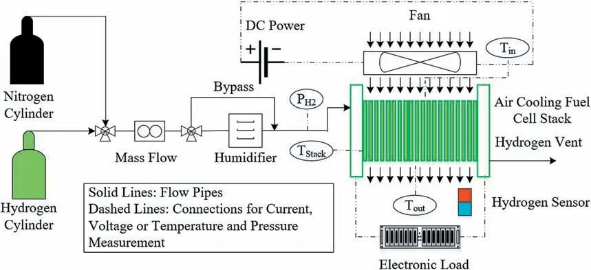
Fig.1.Schematic of test cross-link relationship.
The galvanostatic EIS was measured from 1000 to 0.1 Hz by alternating the current with a disturbance equal to 10% of the DC current.The impedance spectra of the equivalent circuit model were fitted by using ZView software (Scribner Associates,Inc.).The model was used since it can isolate the cathode charge transfer resistance from the mass transfer resistance loss and accurately captures the oxygen diffusion characteristics at low frequencies [27].Among these,the resistances were the cell ohm resistance (RΩ),which is comprised of uncompensated contact resistance,ions and electrons resistance of cell components of ions and electrons resistance,and the resistance of the interface between cell components [28].Parallel resistor-capacitor circuits were used to simulate the anode;the individual components of the anode circuit describe the charge transfer resistance (Ra) of the hydroxide reaction of the anode catalyst layer and the capacitance of the porous electrode.The circuit modeling cathode consists of a constant phase element in parallel with the resistor,which constitutes the cathode charge transfer resistance (Rc) for the oxygen reduction reaction and the distributed double layer capacitance for the porous electrode.Warburg short element (Wc) was connected in series with Rcto simulate the low-frequency phenomenon of oxygen diffusing to the active part of the cathode in the electrode through porous GDL [29].
Detail experimental conditions were listed in Table.2.The detail of test matrix cases was listed in Table .3.Table .4 summarizes the AOLTPEMFC experimental parameters.

Table 2 Experimental conditions of AO-PEMFC.
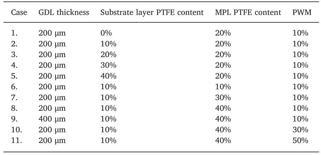
Table 3 Test case of air-cooled open-cathode LT-PEMFC.
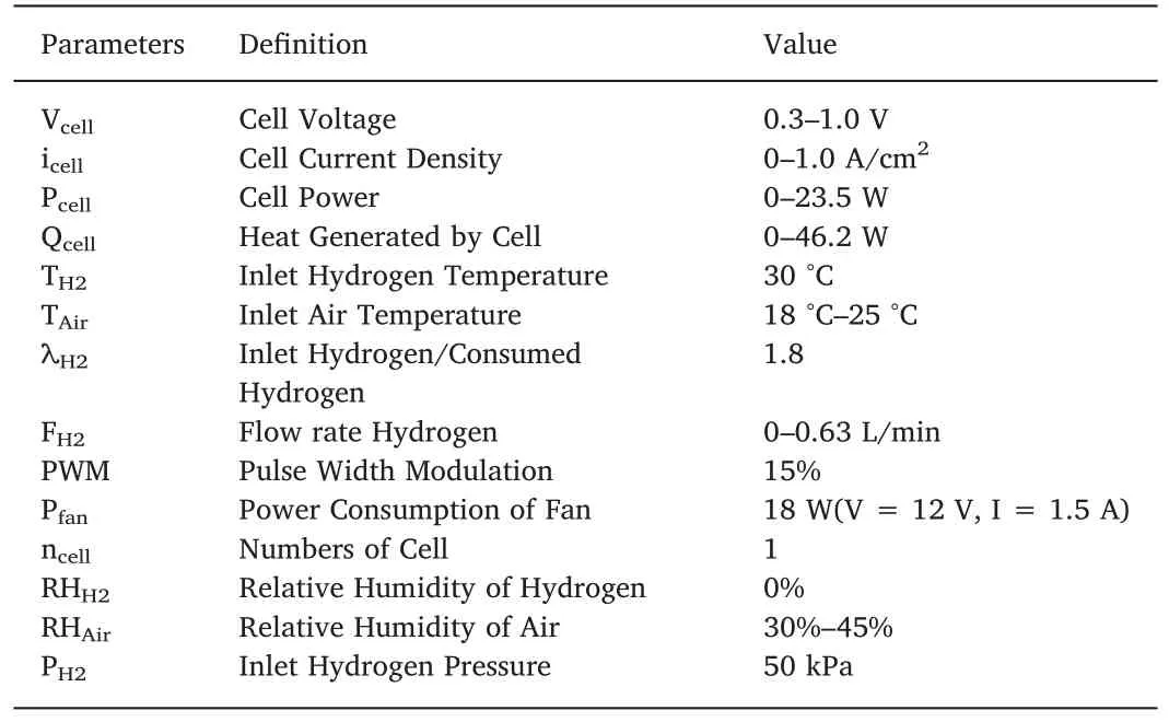
Table 4 AO-LTPEMFC experimental parameters.
3.Results
During the process,the H2input temperature,pressure,humidity,and stoichiometry ratio were set at 30 °C,50 kPa,0%,and 1.8,respectively.The bolt torque was 1.1 N m,the end-plate size was 200 mm×65 mm,the thickness was 25 mm,the materials of endplate were fiberglass board.
3.1.Effect of different PTFE content in the substrate layer of GDL
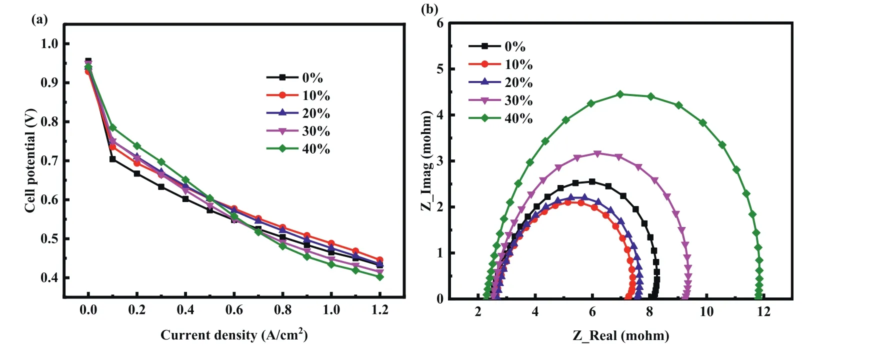
Fig.2.Performance comparison of cells with different PTFE content in the substrate layer (a) voltage vs.current density (b) Electrochemical impedance spectroscopy.
The variation of PTFE content in the substrate layer and MPL layer of GDL have a significant influence on the management for the water,heat and gases in fuel cells.The single fuel cell with GDL (thickness 200 μm) with MPL 20% PTFE loading was fabricated to analyze the influence of the PTFE loading on the substrate layer of GDL on the cell performance.Each PTFE loading on the substrate layer was about 0%,10%,20%,30% and 40%.Fig.2 shows the polarization curves of AOLTPEMFC with different substrate layer PTFE loading.The results curve could be divided into three regions.In the first region,the current density was lower than 0.5 A/cm2,and the single cell with the highest substrate layer PTFE content achieved the best performance.In the second region,the current density was between 0.5 A/cm2and 0.7 A/cm2,and the single cell performances showed irregular changes with increasing the substrate layer PTFE content.With the increase of current density,the performance of the cell with substrate PTFE content of 40% showed a declining trend.When the current density is 0.7 A/cm2,the single cell with the highest substrate layer PTFE content achieved the lowest performance.Simultaneously,the single cell performance with 10% substrate layer PTFE content was 0.58 V/0.6 Acm−2which was the highest in all GDL with different substrate layer PTFE content.In the third region,the current density was above 0.7 A/cm2,and it showed that the cell with 10% substrate layer PTFE content always obtained the best performance.
In general,the fuel cell performance increases with the increase of substrate layer PTFE content firstly,and then decreases.And the 10%substrate layer PTFE content which makes the cell performance increase to the peak value is proper for the GDL for AO-LTPEMFCs.The main reason is that,as the substrate layer of the GDL is treated by PTFE,the porous skeleton in the carbon paper can be overlapped,in order to decrease pore size as shown in Table 5 and Fig.3,and increase the air transfer resistance from gas channel to the catalyst layer.Simultaneously,the substrate layer of GDL treated with PTFE becomes hydrophobic that will meaningfully impact the water management of the fuel cell [23].Thus,the PTFE content of substrate layer GDL not only affect the porosity of GDL but also affect the water management between catalyst to channel.And the water content of the membrane is an important factor since enough generated water could enhance the proton conductivity near the membrane.There is a balance between mass transfer and membrane water content.When the substrate PTFE content increases from 0% to 10%,the average aperture does not change much (21.9 μm-20.1 μm) and the ability of mass transfer is maintained.Simultaneously,10% increment of the substrate PTFE content enhances the hydrophobicity and water holding capacity of GDL,improves the proton conductivity of the membrane,which results in the improvement of cell performance.However,with the continuousincrease of substrate PTFE content(greater than 10%),the average pore diameter decreased sharply ((20.1 μm-8.6 μm),the mass transfer resistance increases,the oxygen supply is insufficient,and the cell performance decreases.The optimum PTFE content of the substrate layer is 10%,which ensures the air mass transfer and the moisture on the membrane.
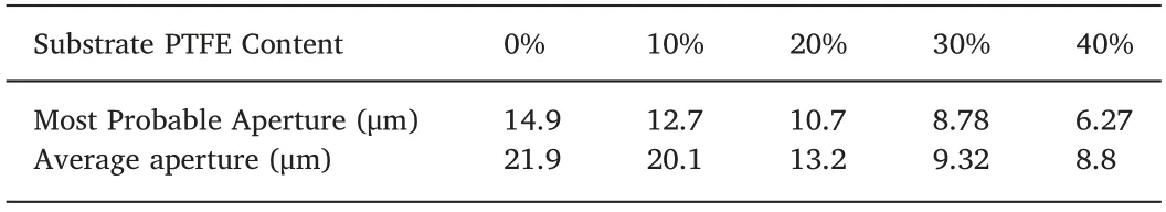
Table 5-GDL pore size distribution with different substrate PTFE content.
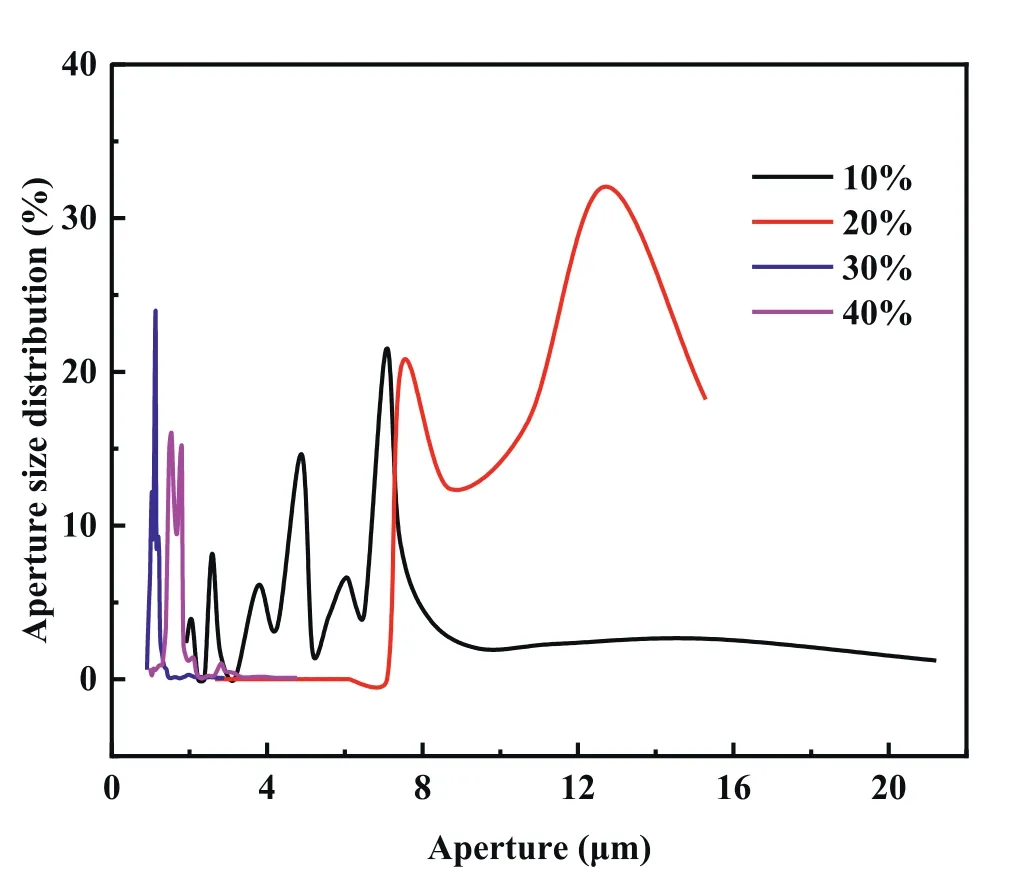
Fig.3.Pore size distribution of GDL.
Fig.4 shows the cathode outlet surface temperature distribution of different GDL with different substrate layer PTFE content at the current density of 0.8 A/cm2.The outlet surface temperature of the cathode side was the lowest when the PTFE loading of the substrate layer was 10%,and the temperature was the highest when the PTFE loading of the substrate layer was 40%.When the PTFE loading of the substrate increased,the GDL became less porous and the resistance of GDL also increased.The increase of ohmic loss increases,and the decrease of heat dissipation capacity,resulted in the high temperature of the cell with high PTFE content under the same conditions.High temperature accelerated the evaporation of water,resulting in dehydration of membrane and degradation of fuel cell performance.
3.2.Effect of different MPL PTFE content of GDL
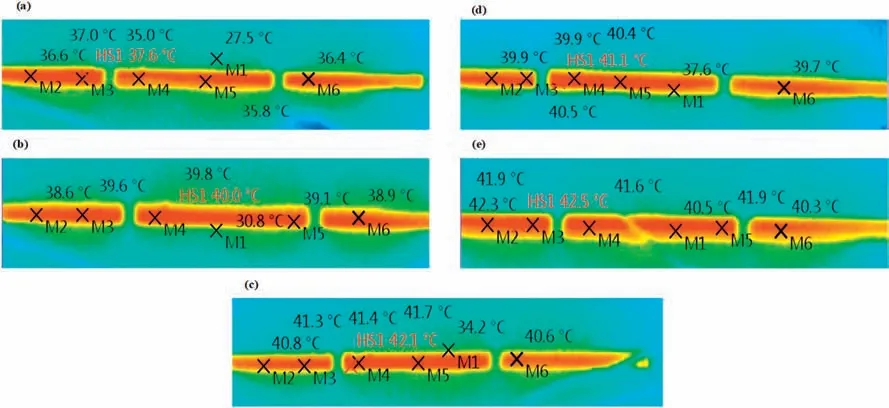
Fig.4.Temperature distribution of the different substrate layer PTFE content of 0.8 A/cm2 (a)0% (b) 10% (c) 20% (d) 30% (e) 40%.
Fig.5 gives polarization performance and Nyquist plots under different MPL PTFE content.Table 6 shows the pore size distribution with different MPL PTFE contents.Fig.5(a) shows that the performance of the fuel cell linearly increased with the increase of MPL PTFE content.When MPL PTFE content was 40%,the cell performance (0.59 V/0.8 Acm−2)was obviously better than that of the other three kinds of MPL PTFE content.The results reveal that increasing MPL PTFE content in GDL could improve the cell performance,especially at high current densities where more water generated.Fig.5(b) shows the ohmic resistance and the total polarization resistance of AO-PEMFC with variations of the MPL PTFE content at the current density of 0.8 A/cm2.It can be seen that the total polarization resistance decreased with the increase of MPL PTFE content,and the contact resistance remained stable in four different MPL PTFE content in GDL.MPL is the component closest to the catalytic layer except for the membrane,the increase of MPL PTFE content has more obvious impacts on the cell performance than the increase of substrate PTFE content.With the increase of MPL PTFE content,the hydrophobicity of MPL was strengthened,most of the water generated by the cathode catalyst layer kept in the CCM components,the membrane was sufficiently humidified,leading to the increase of proton conductivity and cell performance.
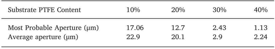
Table 6-GDL pore size distribution with different MPL PTFE content.
Fig.6 shows the temperature distribution of a single cell at different MPL PTFE content in GDL with the current density of 0.8 A/cm2.Although the increase of MPL PTFE content slightly increased the ohmic resistance and ohmic loss,the more water with high heat capacity was kept in CCM,the temperature would not increase with the increase of MPL PTFE content.The enhancement of proton conductivity also reduced charge transfer resistance,resulting in less generation of waste heat.Thus,the outlet temperature of the cathode side decreased.
According to the test results in Section 3.1 and 3.2,the optimalPTFE content of substrate and MPL was 10%and 40%,respectively.At such PTFE content,the cell had the best performance at high current density.Since the untreated carbon paper is hydrophilic,adding appropriate amount of PTFE is conducive to the formation of more gas channels in the cell,which is conducive to strengthen the mass transfer process of the fuel cell.However,excessive PTFE will also lead to the decrease of conductivity and increase of ohmic resistance of GDL,and eventually lead to the decline of the cell performance.As for the difference of the optimal PTFE content in the substrate layer and the MPL,the porosity of the substrate layer is much larger than that of the MPL,MPL needs more PTFE to form enough gas channels to reduce the mass transfer impedance of the cell.
3.3.Effect of different thicknesses of the substrate layer
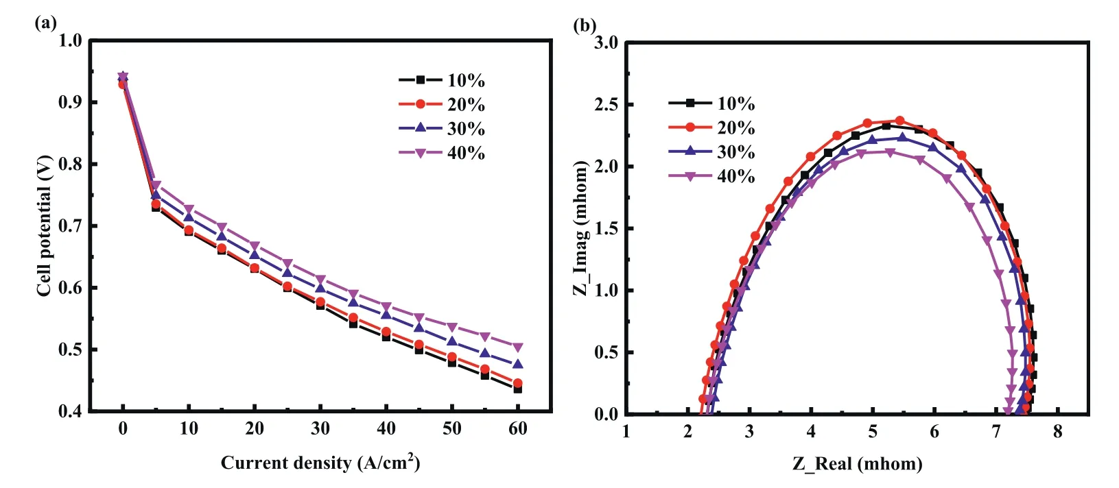
Fig.5.Performance comparison of cells with different PTFE content in MPL (a) voltage vs.current density (b) Electrochemical impedance spectroscopy.

Fig.6.Temperature distribution of the different MPL PTFE content of 0.8 A/cm2 (a) 10% (b) 20% (c) 30% (d) 40%.
The influence of the thickness of the substrate layer (200 μm and 400 μm) on cell performance was investigated,as shown in Fig.7.The substrate layer PTFE content was 10%,and the MPL PTFE content was 40%.The recorded data presented in Fig.7(a) show that the performance decreased with the increase of substrate layer thickness.Although the evaporation decreased with the increase of substrate layer thickness,it also needs much more diffusion time for O2to transfer from cathode channel to catalyst layer,as well as the rapid liquid water saturation [30],which in turn leads to the decrease the performance and increase the total polarization resistance as shown in Fig.7(b).
The impedance data of the fuel cell with different substrate layer thicknesses were obtained by the equivalent circuit fitting of EIS.As shown in Fig.7(b),the ohmic resistance of the cell with 400 μm substrate layer was 7.49 mΩ,which was 5.19 mΩ higher than that of the cell with 200 μm substrate layer (2.30 mΩ).This is mainly due to the increase of bulk resistance caused by the increase of the substrate thickness,and the contact resistance of the surface is basically unchanged.The charge transfer resistances of the anode and cathode of the two kinds of substrate layers were kept in the same order of magnitude,and the change was not obvious.It should be worthy noted that with the increase of substrate thickness,the Warburg impedance representing mass transfer resistance increased from 0.21 m Ω to 10.54 m Ω,which is the principal reason for the decline of cell performance.The thicker substrate layer also leads to poor thermal management.As shown in Fig.8,when the thickness of the substrate layer was 400 μm,the hotspot temperature was attained 45.3 °C,which was 5 °C higher than that of the cell with 200 μm substrate layer.This temperature phenomenon is also consistent with the performance in Fig.7(a).Thus,compared with the 400 μm in the same operating conditions,the substrate layer thickness of 200 μm may be the optimal value in the application.
3.4.Effect of different airflow rate
The airflow rate is an important factor in the operation of AOLTPEMFC[23].Based on the above results,the single fuel cell with the 10% of substrate layer PTFE content,40% of MPL PTFE content,and 0.2 mm in the thickness of GDL was assembled and investigated the influence of airflow on the cell performance.The airflow rate was controlled by the PWM of the fan,which was set at 10%,30%,and 50%,respectively.Fig.9 shows the voltage variation of different PWM at the current density of 0.8 A/cm2,1.0 A/cm2,and 1.2 A/cm2.When the current density was 0.8 A/cm2,the voltage of a single cell decreased with the increase of PWM,since the temperature of the cell was reduced by the fan resulting in the decrease of electrochemical reaction rate.When the current densities were 1.0 A/cm2and 1.2 A/cm2,the cell achieved optimum performance when the PWM was 30%.Since the increase of PWM can reduce the cell temperature while it also can increase the condensation of water in the cell and increase the proton conductivity in the membrane.There is a balance between the reduction of temperature and enhancement of proton conductivity.For the cell working under 1.0 A/cm2and 1.2 A/cm2,the PWM of 30%was the balance point which can achieve optimum performance.
4.Conclusions
A new way is suggested to divide the content of PTFE in GDL into two parts which were the content of PTFE in the substrate layer and the content of PTFE in MPL,and the influence of these parameters on the performance of AO-LTPEMFC combined with the thickness of GDL in crucial operation conditions is scrutinized.
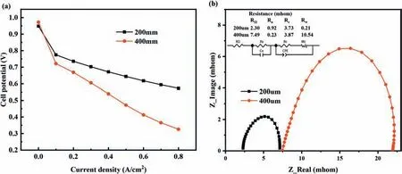
Fig.7.Performance comparison of cells with different substrate layer thicknesses(a) voltage vs.current density,(b) electrochemical impedance spectroscopy.
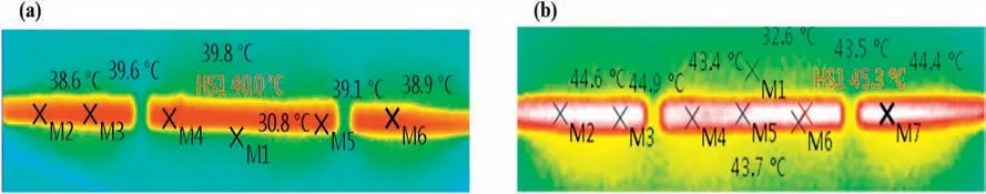
Fig.8.Temperature distribution of the different substrate layer thickness content in 0.8 A/cm2 (a) 200 μm (b) 400 μm.
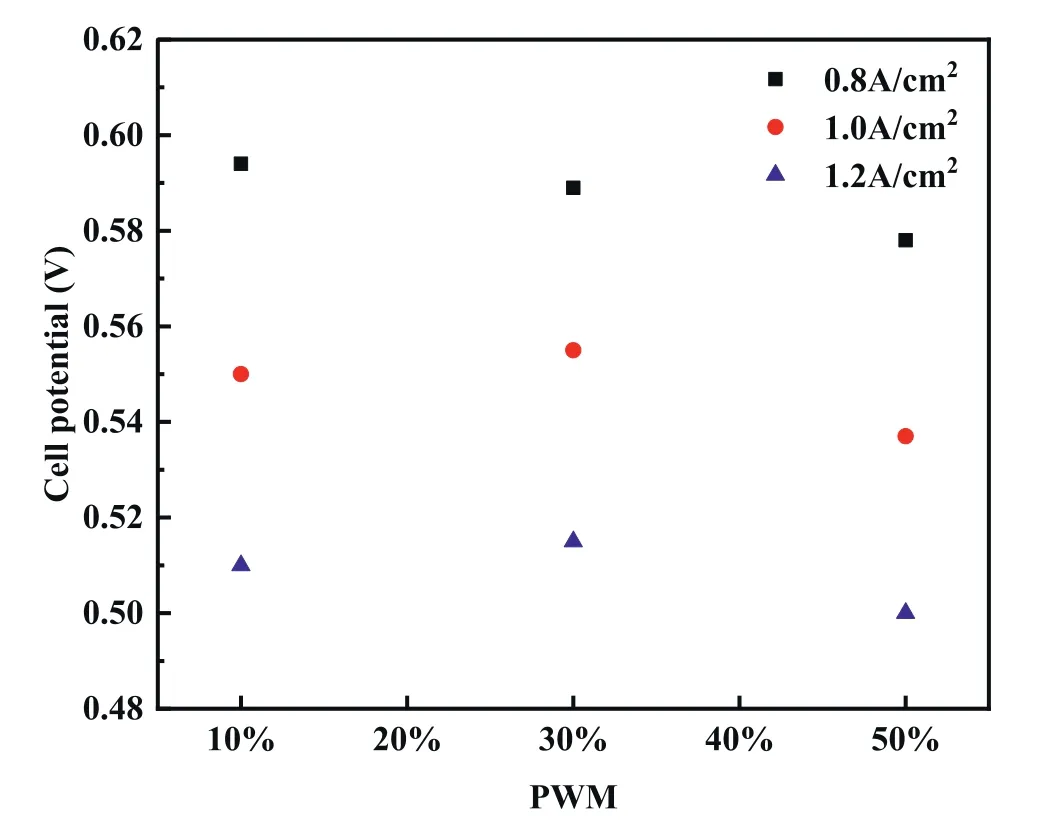
Fig.9.Cell performance with different PWM of air fan.
The optimal PTFE content in the substrate layer,PTFE content in MPL,and the thickness of GDL are figured out and verified through cell performance and EIS test.The maximum performance of fuel cell with 10%PTFE content in the substrate layer and 40%PTFE content in MPL is 0.11 V larger than the lowest in the same thickness of GDL at 0.8 A/cm2,which is 0.594 V.Simultaneously,the effect of PWM of the fan also has been investigated in detail.The significance of the performance improvement is conducted based on the experiment with different PTFE content in GDL.The PWM of the fan also has an important effect on the performance of AO-LTPEMFC,which is significant for water management and air mass transfer.Therefore,it can be concluded that the study of different PTFE content with GDL can effectively enhance the water and heat management,and performance of AO-LTPEMFCs.
The basic principles of the design and the experimental results of the present paper can be used for and AO-LTPEMFCs design and also helpful for other fuel cell stack designs.
Declaration of competing interest
The authors declare that they have no known competing financial interests or personal relationships that could have appeared to influence the work reported in this paper.
Acknowledgments
This work was financially supported by the National Key Research and Development Program of China (2017YFB0102701),the Shenzhen Peacock Plan (KQTD2016022620054656),Guangdong Innovative and Entrepreneurial Research Team Program (2016ZT06N500),Development and Reform Commission of Shenzhen Municipality 2017(No.1106),Guangdong Provincial Key Laboratory of Energy Materials for Electric Power (2018B030322001).
 Progress in Natural Science:Materials International2020年6期
- Progress in Natural Science:Materials International的其它文章
- Key materials and technologies for fuel cells
- Experimental measurement of proton conductivity and electronic conductivity of membrane electrode assembly for proton exchange membrane fuel cells
- Nickel-introduced structurally ordered PtCuNi/C as high performance electrocatalyst for oxygen reduction reaction
- Large specific surface area S-doped Fe-N-C electrocatalysts derived from Metal-Organic frameworks for oxygen reduction reaction
- Surface modifications of Pt-based atomically ordered nanoparticles to improve catalytic performances for oxygen reduction reaction
- Accelerated Test of Silicone Rubbers Exposing to PEMFC environment