
Experimental study of single-row chevron-jet impingement heat transfer on concave surfaces with different curvatures
2019-12-19 02:06YuanweiLYUJingzhouZHANGXichenLIUYongSHAN
CHINESE JOURNAL OF AERONAUTICS 2019年10期
Yuanwei LYU, Jingzhou ZHANG, Xichen LIU, Yong SHAN
Jiangsu Province Key Laboratory of Aerospace Power System, College of Energy and Power Engineering, Nanjing University of Aeronautics and Astronautics, Nanjing 210016, China
KEYWORDS
Chevron nozzle;
Concave surface;
Experimental test;
Heat transfer;
Jet impingement
Abstract To address the curvature effect on single-row chevron-nozzle jet impingement heat transfer on concave surface,a series of experiments are conducted in the present investigation.Four concave surfaces including one semi-cylindrical concave surface and three parabolic concave surfaces with different width-to-depth ratios are tested under three typical Reynolds numbers (Re=5000,10000 and 15000) and several dimensionless nozzle-to-surface distances ranging from 1 to 8. The results show that the concave curvature has a clear impact on chevron-nozzle jet impingement heat transfer, tightly dependent on jet Reynolds number and impinging distance. In general, the semicylindrical concave surface produces the highest longitudinally-averaged Nusselt number at the leading line of concave surface. Under a low jet Reynolds number, the parabolic concave surface with a highly curved curvature produces higher longitudinally-averaged Nusselt number at the leading line and more uniform longitudinally-averaged Nusselt number distribution along the curvilinear direction. However, the longitudinally-averaged Nusselt number at the leading line of concave surface is the lowest for the highly curved surface under a high jet Reynolds number and large impinging distance. In comparison with the round-nozzle, chevron nozzle plays a more significant role on improving jet impingement heat transfer at small impinging distances.
1. Introduction
Jet impingement has been widely used in the aeronautical engineering, e.g., intensive cooling of gas turbine hot section components (such as turbine blades, combustor liners, exhaust nozzles),1-3anti-icing of aircraft critical surfaces (such as wings, engine inlet guide struts, nacelle lips).4-6Although vast investigations have been performed on this classical heat transfer scheme,is still a remarkable issue by now,in order to quest more and more efficient means for achieving the maximized heat transfer rate with limited bleed air usage.
It had been well demonstrated that the jet impingement heat transfer could be effectively enhanced by shaping the nozzle geometry.7Among various shaped nozzles, the tabbed or chevron nozzle received much attention recently. This kind nozzle was initially motivated for the purpose of co-flow mixing enhancement.8-10As the tabs or chevrons could initiate large- and small-scale vortical motion, the near-field jet was effectively excited, resulting in strong momentum transfer between coaxial flows.Owing to this feature,the coherent vortical structure of round impinging jet would be changed by the tabbed or chevron jet. Violato et al.11performed an investigation on 3-D vortex dynamics of chevron jet impingement on a flat plate. Their results indicated that the vortical motion and turbulence intensity of chevron jet approaching to target surface were promoted by the streamwise vortices shedding from chevron notches.As a consequence,the chevron jet resulted in a stronger heat transfer enhancement. The benefit of using tabbed nozzle on improving jet impingement heat transfer was also demonstrated by Yu et al.12,13in a confined straight channel with/without presence of an initial crossflow. It was illustrated that the tabbed jets increased heat transfer in the vicinity of impingement stagnation up to 25% in the situation without initial crossflow but only 10%with initial crossflow,in comparison with the corresponding round jets. Vinze et al.14experimentally investigated the influence of chevron nozzle geometry on jet impingement heat transfer distribution over a flat plate. Ten chevron nozzle configurations were designed with different chevron number and penetration. It was revealed that an increase of 26%-38%in local Nusselt number could be achieved by the chevron nozzle in comparison with the round nozzle.Lyu et al.15performed an experimental study of chevron jet impingement on a flat surface under a series of jet Reynolds numbers ranging from 5000 to 20000 and nozzleto-surface distances ranging from 1 to 8. It was found that 6-chevron nozzle with a chevron length-to-nozzle diameter of 0.6 achieved more favorable heat transfer enhancement.By adopting the chevron nozzle, Guan et al.16,17performed numerical and experimental investigations to evaluate its application in the hot-air anti-icing configuration of engine intake surfaces.In their studies,the overall heating effectiveness was concerned by using conjugate heat transfer model (considering external cold-air forced flow, wall thermal conduction, and internal hot-air impingement). The area-averaged heating effectiveness in the vicinity of conical-wall leading edge could be increased approximately 20%by the chevron nozzle in comparison with the round nozzle.
To our knowledge, little attention had been paid for illustrating the chevron jet impingement heat transfer on curved surfaces.As the target surface curvature is an important factor affecting the wall jet flow dynamics and consequently the heat transfer process,the conclusion derived on a flat surface is generally distinct from that on a curved surface.18-21For example,Zhou et al.22experimentally studied the local and average heat transfer characteristics of a single round jet impingement on concave surfaces. It was illustrated that the relative surface curvature(d/D)shows different effect on the heat transfer performance. At a fixed surface diameter (D), the increase of relative surface curvature (d/D) increased both stagnation and average heat transfer. However, the case was opposite at a fixed nozzle diameter (d).
The assessment of curvature effect on single-row chevronjet impingement heat transfer on curved surfaces is the main concern of current research. To address this issue, a series of experiments are conducted in the present investigation. Four concave surfaces including one semi-cylindrical concave surface and three parabolic concave surfaces with different curvatures are taken into considerations. The comparison with the round nozzle is also made.
2. Experimental setup
The experimental setup is schematically displayed in Fig.1(a).The impinging air is provided by a compressed air supply. A filter is installed upstream of the pressure regulator. The flow rate is controlled and measured by a pre-calibrated mass flow controller.After routing through the supply passage,the compressed air is fed into a transmission chamber and then distributed into a row of jet tubes. Each jet tube has a length (l)of 120 mm and inner diameter (d) of 10 mm. This length-todiameter ratio (l/d) of 12 ensures a fully developed turbulent velocity profile at the nozzle exit.
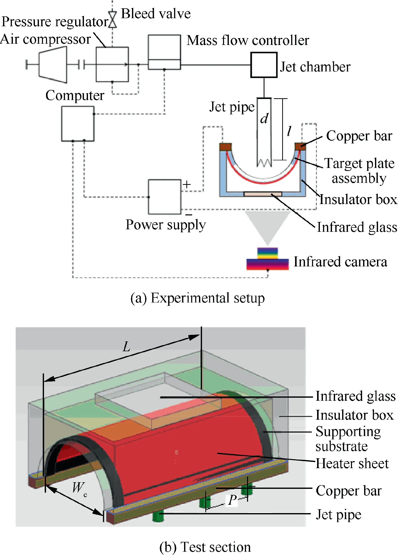
Fig. 1 Schematic test setup of jet impingement.
The target plate assembly is composed of a supporting substrate and a thin stainless steel sheet, as seen in Fig. 1(b). The supporting substrate is made of a transparent plastic plate with a thickness of 5 mm, by manufacturing a rectangular opening at the center. On the supporting substrate, a 0.05 mm thick stainless steel sheet is tightly mounted, covering the central opening of transparent plastic plate. This stainless steel sheet is heated by DC current. By recording the electric voltage(V) between two copper bars connecting to the heating sheet and the current (I), the joule heating power (qjoule) is determined.Three jet tubes are arranged in a line along the longitudinal direction with a fixed jet-to-jet pitch (P/d) of 5. The length of concave surface (L) is 15 times nozzle diameter(15d). Both longitudinal ends of concave cavity are covered by thermally-adiabatic plate.
To minimize the heat losses from the rear surface of heating sheet, an insulator box is adopted to enclose the target plate assembly, as seen in Fig. 1(b). On the front plate of insulator box, an infrared glass with a high transmissivity (about 0.97)in the long infrared band is placed for the temperature measurement by infrared camera. Its size is 60 mm (width)×100 mm (length)×5 mm (thickness).
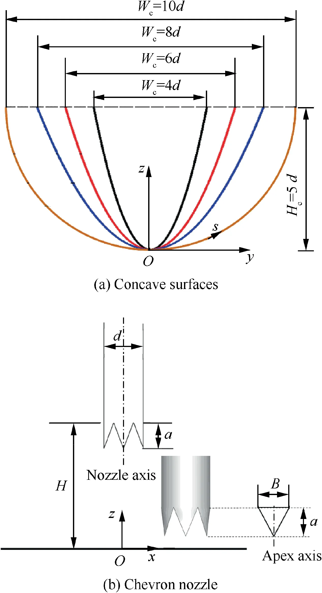
Fig. 2 Schematic diagram of test model.
Four concave surfaces are tested in the current study,including one semi-cylindrical concave surface (baseline case)and three parabolic concave surfaces with different curvatures,as shown in Fig.2(a).The parabolic concave surface curvature is changed by varying the base width (Wc=8d, 6d and 4d,respectively) while maintaining the depth of concave cavity(Hc) at 5d. The concave profiles are listed in Table 1. The jet-nozzle centerline is perpendicular to the base plane and orthogonal to the leading line of concave cavity. A specific 6-chevrons nozzle is used in the present study, which is schematically shown in Fig. 2(b). It has six chevrons distributed uniformly in the circumferential direction.Each chevron apex axis is parallel to the centerline of the nozzle. The chevron length(a)is set as 6 mm and the arc width of chevron base (B) was πd/6, giving a length-to-width ratio of 1.15.According to the previous works,11,14the impinging distance or nozzle-to-surface distance (H) is defined as the distance between target surface and chevron orientation section. By using a traverse system, the impinging distance is adjusted in a certain range between H/d=1 and H/d=8. The coordination system is also specified in Fig. 2. The longitudinal direction of the concave surface is defined as x-direction and the curvilinear direction is defined as s-direction.For comparisons,the round-nozzle jet impingement heat transfer is also tested.
3. Measurements and data processing
For the multi-jet impingement,the jet Reynolds number(Re)is determined according to the nozzle diameter (d) and bulkaveraged jet velocity (uj)
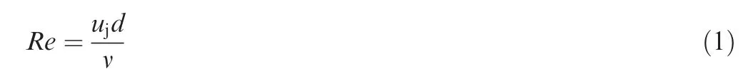
where v is the kinematic viscosity of the jet. In the current study, the jet Reynolds number is adjusted by a calibrated mass flow controller, ranging from 5000 to 15000.
The target temperature, measurement by infrared camera,is same as that adopted by Guan et al16.Both the surface treatment(pre-sprayed with a uniform black paint)and calibration test (by using thermocouples) are conducted in advance to ensure the accurate temperature measurement.
Considering the heat loss from the backside of heating sheet to ambient,the local convective heat transfer coefficient on the target surface is evaluated as
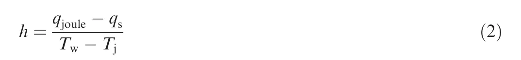
where Twis the target temperature, Tjis the impinging jet temperature, qjouleis the joule heating power per unit area or the input heat flux, qsis the heat loss per unit area from the backside of heater surface.
The heat loss from the backside surface of heating sheet to the ambient is predicted approximately by using the empirical relation of natural convection heat transfer from a vertical flat surface,23according to the measured mean temperature over the outer surface of the insulator box by eight thermocouples.

where Taand Tbare the ambient temperature and the averaged wall temperature on the outer surface of insulator box exposed to the ambient surrounding, respectively. hnbis the natural convective heat transfer coefficient.
In the current tests, the joule heating power per unit area(qjoule) is fixed at 4500 W/m2. The heat loss is found to be within 5% of the power input.
The local Nusselt number (Nu) on the target surface is defined as
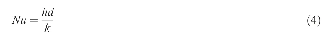
where k is the thermal conductivity of the impinging jet.
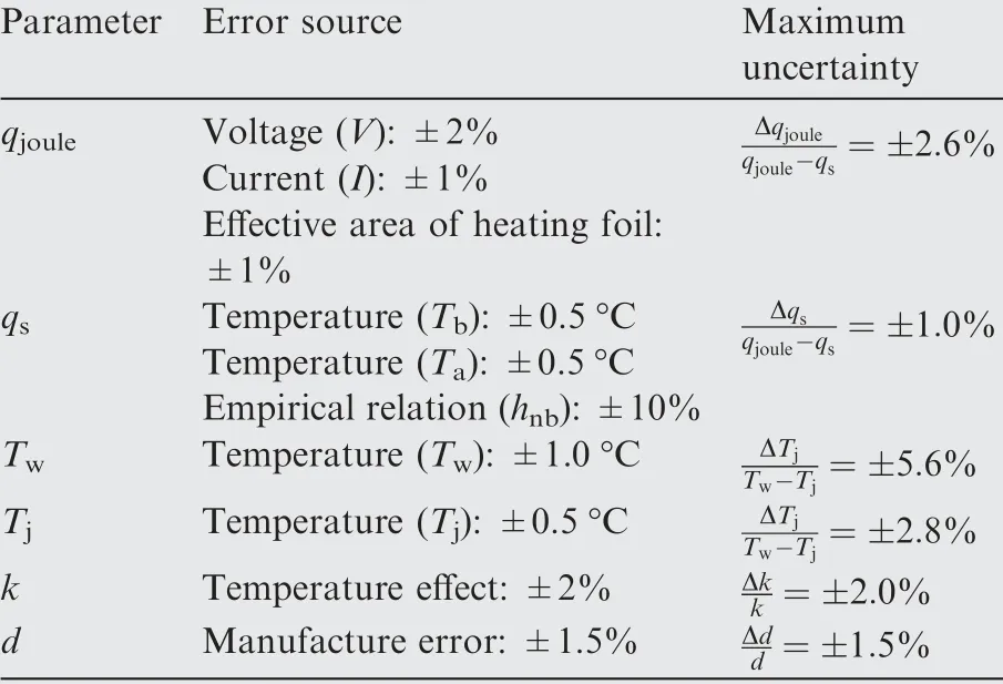
Table 2 Standard uncertainties of independent parameters.
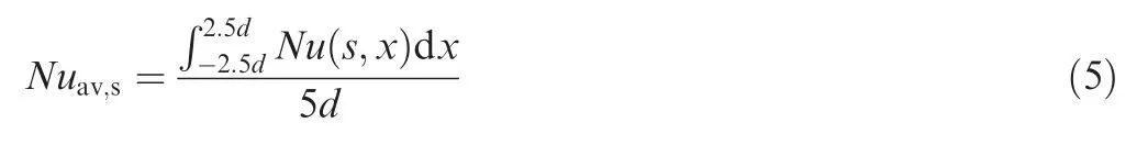
In the present, longitudinally-averaged Nusselt number on the target surface along curvilinear direction is adopted. As the jet-to-jet pitch is fixed at 5d in the current study, thus the longitudinally-averaged Nusselt number is determined by Total uncertainty,for the local Nu measurement,comprises the uncertainties of all parameters that affect the experiment in different ways. According to the methodology of error transfer,24the standard uncertainty of the measurement is obtained by making a combination of the input standard uncertainties and expressed as following equations:
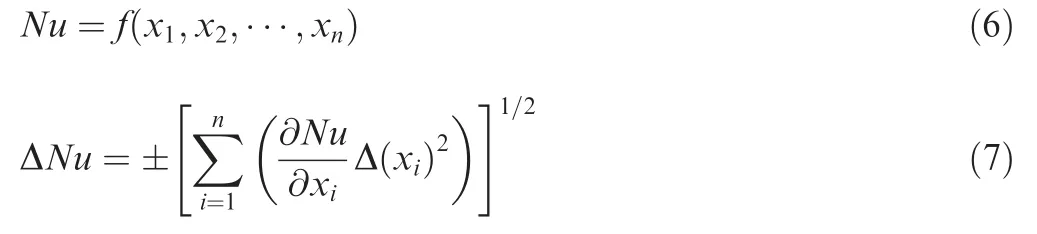
where f is a function of Nu in terms of input independent parameters (x1, x2, ..., xn). Δ(xi) is the standard uncertainty of independent parameter xi. In the current estimation, six independent parameters are selected according to Eq. (2) and Eq. (4), such as qjoule, qs, Tw, Tj, k and d.
The standard uncertainties of independent parameters are summarized in Table 2.By using Eq.(7),the maximum uncertainty in the measurement of Nusselt number is approximately±7.3%.
4. Results and discussion
4.1. Local Nusselt number distribution
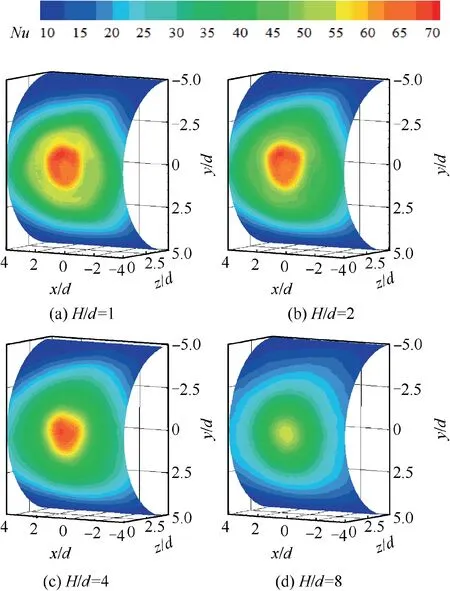
Fig. 3 Local Nusselt number distribution on semi-cylindrical concave target by round-jet impingement (Re=10000).
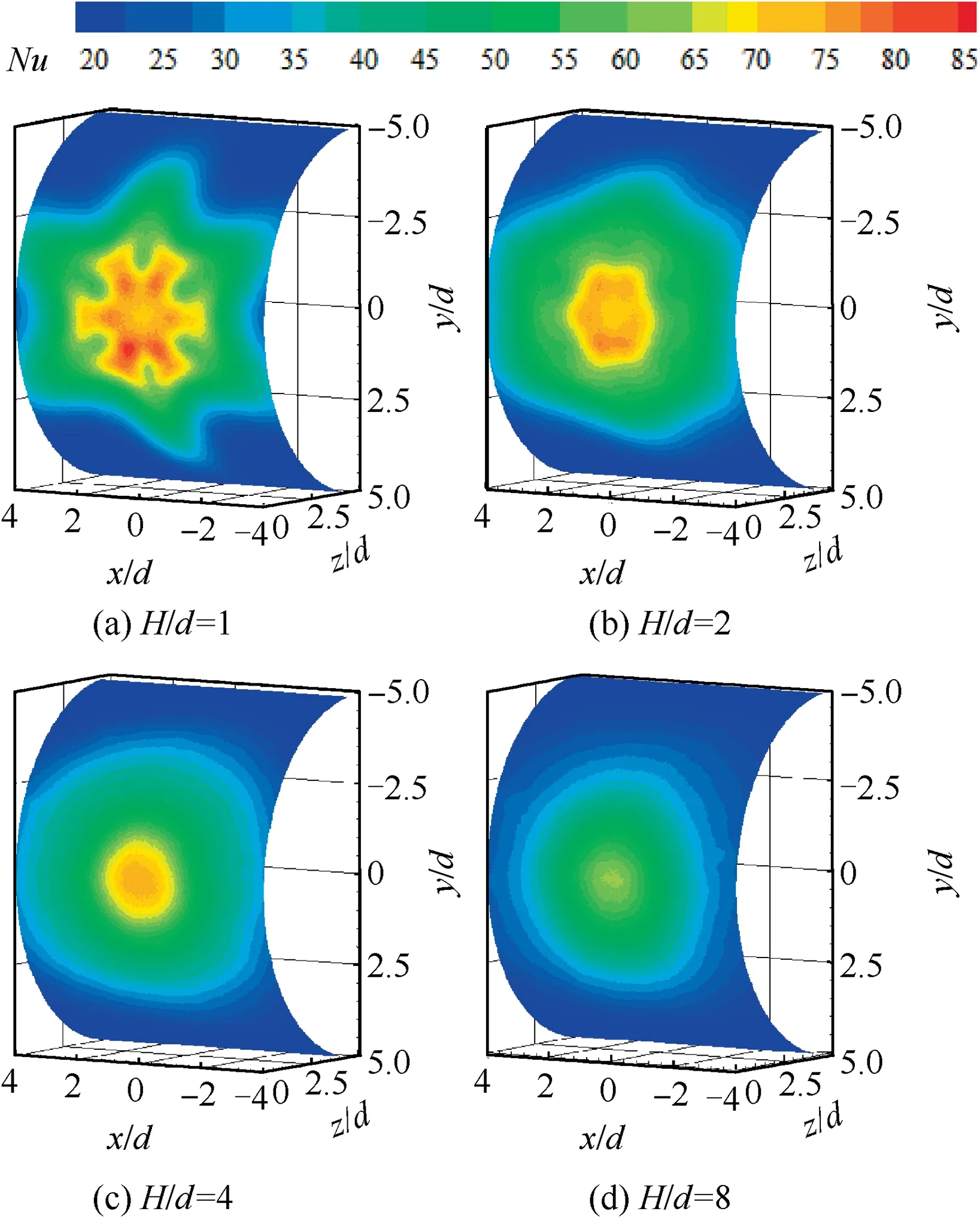
Fig. 4 Local Nusselt number distribution on semi-cylindrical concave target by chevron-jet impingement (Re=10000).
Fig. 3 and Fig. 4 present the local Nusselt number distributions on the semi-cylindrical or baseline concave surface under Re=10000, impinged by single round jet and single chevron jet respectively, at different nozzle-to-surface distances. For the round-nozzle jet impingement, as seen in Fig. 3(a), the‘‘double peaks” feature of the local Nusselt number distribution remains vaguely on the concave surface at a small dimensionless nozzle-to-surface distance of H/d=1. As previously illustrated by Livingood and Hrycak,25for the turbulent impinging jets on flat plates, at a small nozzle-to-surface distance, the impinging jet undergoes a sudden turning of flow direction in the stagnation region, resulting in a strong flow acceleration along the radial direction to promote significant flow transition from a laminar to a turbulent boundary layer at a radial position apart from the stagnation point. Corresponding to this significant flow transition, an annular‘‘hump”with higher heat transfer coefficient occurs surrounding the jet stagnation, forming the secondary or outer peak of the local Nusselt number distribution.With regard to the concave target surface, the transition from a laminar to a turbulent boundary layer is conjectured to be faster due to the destabilization effect,and the transitioning region is less effectively cooled because the natural confinement causes the increase of the mean temperature of the ambient air around the jet.26Consequently, in relative to the flat target surface,the alleviation of the secondary peak on the concave surface is caused by the combined effect of destabilization and confinement due to the concave curvature. However, for the chevron jet impingement, the ‘‘double peaks” feature of the local Nusselt number distribution produced by the round jet impingement is disappeared but replaced by the ‘‘lobed pattern”feature that resembles the shape of the 6-chevron nozzle configuration at H/d=1,as seen in Fig.4(a).Of particular interest is that the lobe peaks of local heat transfer contours are shifted in the radial direction. In the inner lobe-shaped contour, the lobe peaks are in correspondence to the chevron notches. Far away from the jet stagnation, the lobe peaks in outer lobe-shaped contour in correspondence to the chevron apexes.At H/d=2,the lobed feature becomes weaker,as seen in Fig.4(b).With the further increase of nozzle-to-surface distance,as seen in Fig.4(c)and Fig.4(d),the characteristic lobeshaped pattern of local Nusselt number distribution observed at H/d=1 produced by the chevron jet impingement vanishes.At a large dimensionless nozzle-to-surface distance, the chevron jet impingement behaves more similar to the round jet impingement.
Fig. 5 presents the local Nusselt number distributions on the concave surfaces,impinged by a single row of chevron jets under Re=10000 and H/d=4.It is seen clearly that the local convective heat transfer contours in the vicinity of the concave leading edge change gradually from a nearly circular-shape on the semi-cylindrical concave surface (as seen in Fig. 5(a)) to a oval-shape on the highly curved surface(as seen in Fig.5(c)).It is also seen that on the highly curved surface,the local convective heat transfer decreases rapidly along the curvilinear direction far away from the leading line of concave surface.
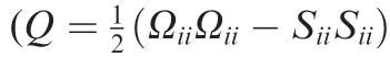
Fig.7 and Fig.8 present the influences of nozzle-to-surface distance on mean and Root Mean Square(RMS)velocity contours of chevron jet impingement on a semi-cylindrical concave surface under Re=5000. At a small nozzle-to-surface distance of H/d=2, the approaching jet has a relatively narrow shear layer and big normal mean velocity, resulting in a strong flow acceleration and consequently large RMS velocity at the wall jet region. With the increase of nozzle-to-surface distance, the shear layer width of approaching jet becomes wider but the peak mean velocity decays more seriously. As the wall jet flow along the concave surface is relatively weak at a large nozzle-to-surface distance,it is the recirculation flow inside a concave cavity becomes obviously.Evidently,onto the impact of the recirculation flow inside a concave cavity, the development of impinging jet is conjectured to be destabilized.In addition, due to the confinement effect, the mean temperature of the ambient air around the jet is certainly increased.These two effects due to the concave curvature lead to an alleviation of the jet impingement heat transfer in the vicinity of jet stagnation.From these figures,it is also found that the wall jet along the longitudinal direction is stronger than that along the curvilinear direction.
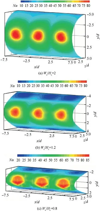
Fig. 5 Local Nusselt number distribution of a row of chevronnozzle jet impingement (Re=10000, H/d=4).
The concave curvature has an important influence on the impinging jet flow inside a concave cavity, as demonstrated in Fig. 9. At a highly curved surface, the confinement effect due to the concave cavity becomes significantly.It is suggested that the concave curvature has two opposite roles on the jet impingement.Firstly,the approaching process of an impinging jet to the target and the development of wall jet along the curvilinear direction suffer the serious confinement effect.Secondly, the lateral diffusion of the wall jet along the longitudinal direction is otherwise promoted. Therefore, the convective heat transfer on a concave surface is tightly dependent on the competition of these two factors having the contrary roles.
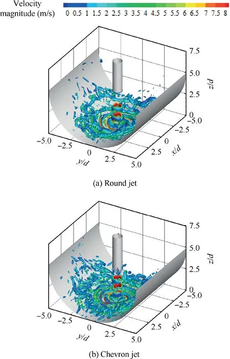
Fig. 6 Computed spatial distribution of coherent structure indicated by iso-contours of Q=500000.
4.2. Comparison between chevron and round nozzles
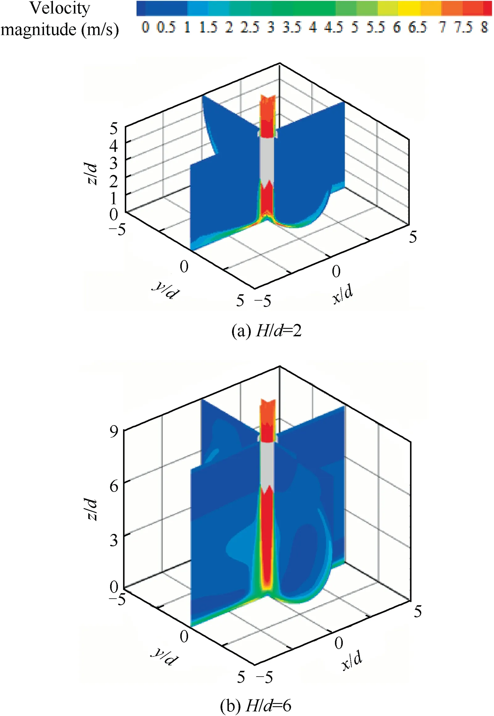
Fig. 7 Computed mean velocity contours of chevron jet impingement on concave surface under Re=5000.
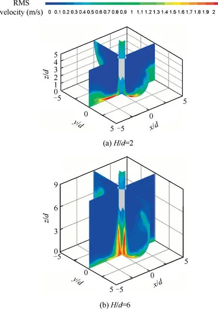
Fig. 8 Computed RMS velocity contours of chevron jet impingement on concave surface under Re=5000.
Fig.10 and Fig.11 present the longitudinally-averaged Nusselt number distributions along curvilinear direction, on the concave surfaces with Wc/Hc=0.8 and Wc/Hc=1.6, respectively. It is confirmed that the chevron jet impingement produces stronger convective heat transfer than the corresponding round jet impingement, especially at small nozzleto-surface distances. Approximately 20%-30% increase of longitudinally-averaged Nusselt number in the vicinity of concave leading is obtained by the chevron-jet impingement under small nozzle-to-surface distances. This value is about 10%-15% at large nozzle-to-surface distances. As illustrated in Fig. 6, the chevron nozzle promotes the vortical motion of impinging jet, which is the main cause of chevron-jet heat transfer enhancement. With the increase of nozzle-to-surface distance, the vortical motion of chevron-jet will be more seriously weakened in comparison with that at a smaller nozzleto-surface distance. For this cause, the role of chevron nozzle on improving the jet impingement heat transfer on concave surfaces is alleviated at larger dimensionless nozzle-to-surface distances.
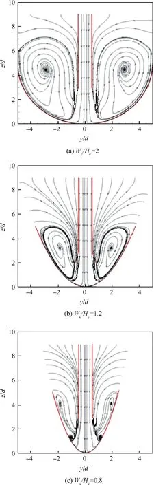
Fig. 9 Computed flow field inside concave cavity under Re=10000.
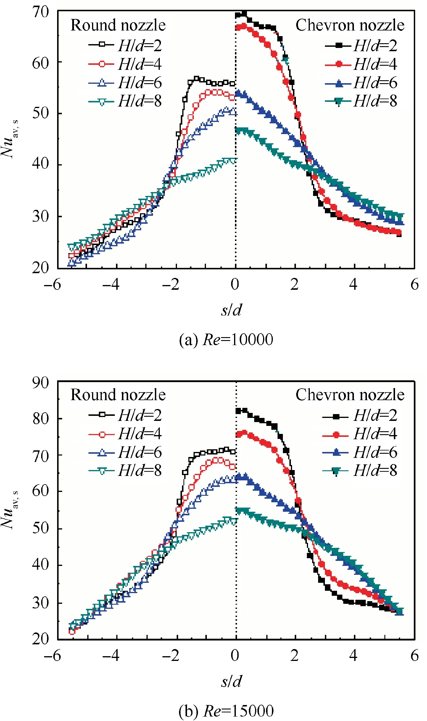
Fig.10 Longitudinally-averaged Nusselt number distribution of jet impingement under concave surface with Wc/Hc=0.8.
On the highly curved surface, as seen in Fig. 10, the longitudinally-averaged Nusselt number decreases rapidly beyond s/d=2 (s is the distance from the stagnation point along the curve surface), at small nozzle-to-surface distances.As illustrated in Fig. 9, the highly curved surface presents a strong confinement to the jet impingement. The wall jet flow along the curvilinear direction is seriously affected so that a rapid decrease occurs beyond s/d=2. At large nozzle-tosurface distances, the stagnation heat transfer is obviously reduced. However, as the impinging jet has a long distance to develop,the sheer layer is broadened,as seen in Fig.8.Thus wider leading zones of concave surface are subjected to the approaching jet, which makes the longitudinally-averaged Nusselt number distributions in the vicinity of concave leading edge more smoothly when compared to the small nozzle-tosurface distances. Consequently, an intersection point of longitudinally-averaged Nusselt number distributions between small and larger nozzle-to-surface distances appears at about s/d=2.5 under the highly curved concave surface. On the slightly curved surface, as seen in Fig. 11, the confinement effect due to the concave cavity is alleviated in comparison with that on the highly curved surface. The longitudinallyaveraged Nusselt number decreases gradually along the curvilinear direction at small nozzle-to-surface distances, in the vicinity of concave leading edge. The intersection point of longitudinally-averaged Nusselt number distributions between small and larger nozzle-to-surface distances is put far away from the jet stagnation,even disappeared in the vicinity of concave leading edge.
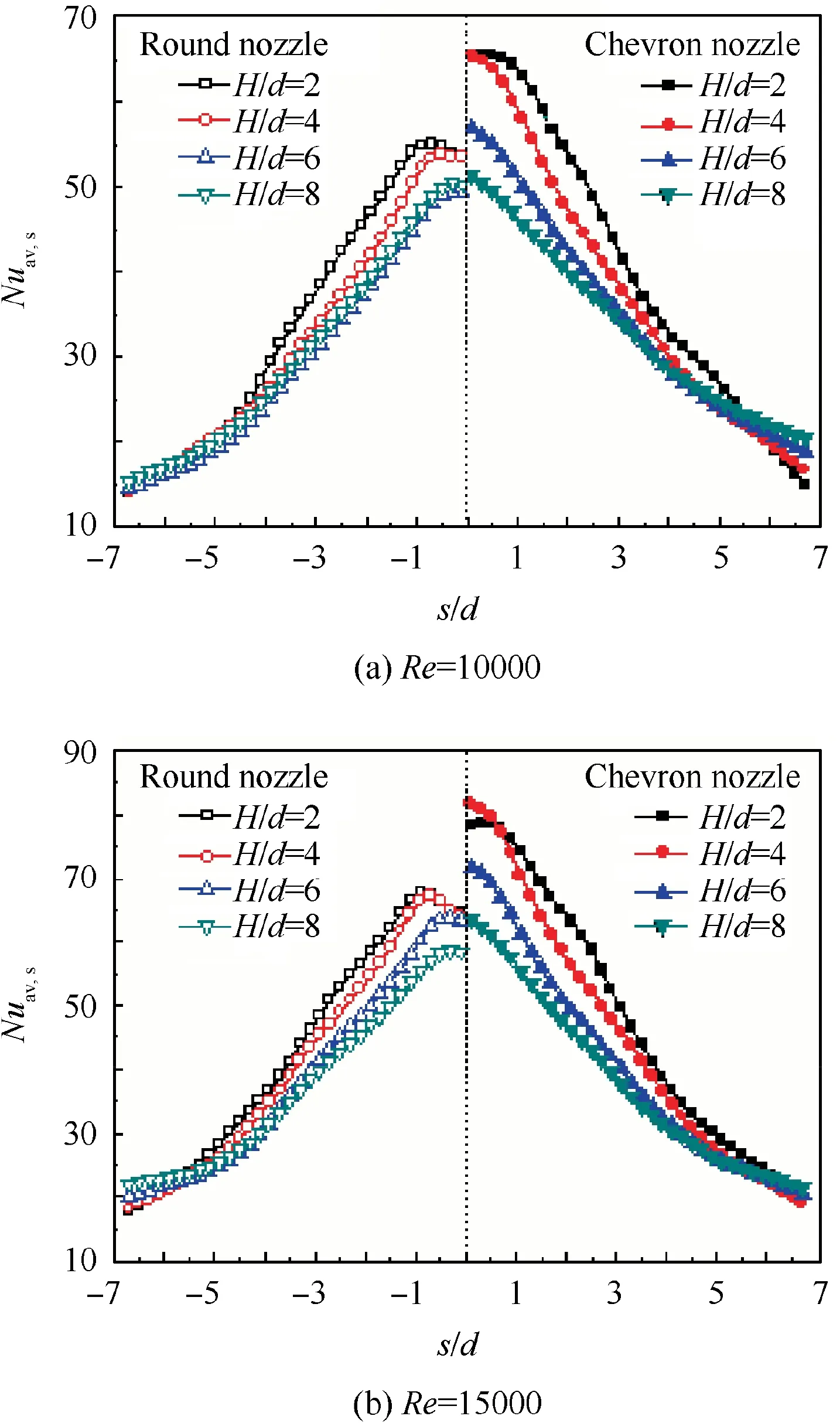
Fig.11 Longitudinally-averaged Nusselt number distribution of jet impingement under concave surface with Wc/Hc=1.6.
4.3. Effect of concave curvature
Fig. 12 and Fig. 13 present longitudinally-averaged Nusselt number distributions along the curvilinear direction,impinged by a row of chevron jets under Re=5000 and Re=15000 respectively.
Under Re=5000, as seen in Fig. 12, the longitudinallyaveraged Nusselt number at the leading edge of semicylindrical concave surface is higher than that on the other concave surfaces. It is interest to find that the narrowest concave surface (Wc/Hc=0.8) produces nearly the same or even a little higher peak longitudinally-averaged Nusselt number at the leading edge than that on the concave surfaces with Wc/Hc=1.2 and Wc/Hc=1.6. As pointed out early, for the jet impingement on a concave surface,the wall jet flow has less momentum to flow along the curvilinear direction but larger flow capacity along the longitudinal direction of the concave surface. The strong lateral-diffusion of wall jet is conjectured to be helpful for improving the uniformity of convective heat transfer in the longitudinal direction. It is also noticed that the concave surface with Wc/Hc=0.8 produces more smooth longitudinally-averaged Nusselt number distribution along the curvilinear direction at large nozzle-to-surface distances, as seen in Fig. 12(c) and Fig. 12(d). Downstream the location of s/d=1.5, the longitudinally-averaged Nusselt number on the concave surface with Wc/Hc=0.8 is obviously higher that the corresponding one on the other concave surface.
However, the situations under Re=15000 are not consistence with the corresponding ones under Re=5000, as seen in Fig. 13. As the jet penetration capacity is tremendously enhanced by the increase of jet ejection velocity,the approaching jet at a small nozzle-to-surface distance (such as H/d=2)is not sensitive to the concave curvature, producing nearly the same longitudinally-averaged Nusselt number at the leading edge, as seen in Fig. 13(a). Also, as the flow momentum of the wall jet along the curvilinear direction is also enhanced under higher jet Reynolds number, the longitudinallyaveraged Nusselt number distribution along the curvilinear direction on the semi-cylindrical concave surface changes more smooth than that on the other concave surfaces. As the increase of nozzle-to-surface distance, the difference of longitudinally-averaged Nusselt number at the leading edge between different concave surfaces is appeared. At large nozzle-to-surface distances, such as H/d=6 and H/d=8, as seen in Fig. 13(c) and Fig. 13(d), the longitudinally-averaged Nusselt number at the leading edge is reduced gradually with the decrease of Wc/Hc. The reason is that the approaching jet toward the target at a large nozzle-to-surface distance is more seriously affected by the strong recirculation flow in the vicinity of concave leading edge, in the case of highly curved surface and large jet Reynolds number.
The effect of concave surface curvature shows complicated influence on the jet impingement. In order to present a global viewing of the average heat transfer for various target structures, the area-averaged Nusselt numbers (Nuav) are adopted here, as displayed in Fig. 14. Two specified areas used for the purpose of average are defined as the zone of 0 ≤s/d ≤2 and 0 ≤s/d ≤5,respectively.In general,at a low jet Reynolds number,as seen in Fig.14(a),the concave surface with a highly curved curvature (Wc/Hc=0.8) is favorable for producing a high longitudinally-averaged Nusselt number at the leading edge and uniform longitudinally-averaged Nusselt number distribution along the curvilinear direction. At a high jet Reynolds number, as seen in Fig. 14(b), the semi-cylindrical concave surface seems to be more favorable for the impingement heat transfer in the vicinity of concave leading.
5. Conclusions
(1) For the chevron jet impingement, the ‘‘double peaks”feature of the local Nusselt number distribution occurred in the round jet impingement is not appeared but instead by the‘‘lobe pattern” feature that resembles the shape of the 6-chevron nozzle configuration at a small nozzle-to-surface distance. At a large nozzle-tosurface distance, the chevron jet impingement behaves more similar to the round jet.
(2) On concave surfaces,the role chevron nozzle on improving jet impingement heat transfer in related to the round nozzle is more pronounced at a small nozzle-to-surface distance. At small nozzle-to-surface distances, the longitudinally-averaged Nusselt number at leading line is increased about 20%-30%. At large nozzle-tosurface distances, this value is only about 10%-15%.
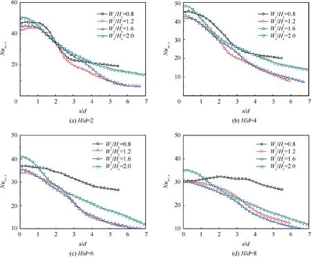
Fig. 12 Longitudinally-averaged Nusselt number distribution of chevron-nozzle jet impingement under Re=5000.
(3) The concave curvature has a clear impact on chevronnozzle jet impingement heat transfer, which is tightly dependent on jet Reynolds number and impinging distance. Under a low jet Reynolds number, the concave surface with a highly curved curvature produces higher longitudinally-averaged Nusselt number at the leading line and more uniform longitudinally-averaged Nusselt number distribution along the curvilinear direction.However, the longitudinally-averaged Nusselt number at the leading line of concave surface is the lowest for the highly curved surface under a high jet Reynolds number and large impinging distance.
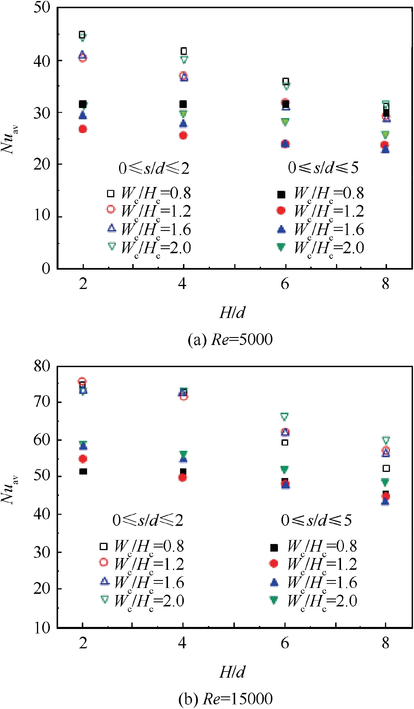
Fig. 14 Area-averaged Nusselt number distribution of chevronnozzle jet impingement.
Acknowledgments
The authors gratefully acknowledge the financial supports for this project from the National Natural Science Foundation of China (No. 51776097), the Open Fund of Jiangsu Province Key Laboratory of Aerospace Power System (No.APS20A7002), and the Postgraduate Research and Practice Innovation Project of Jiangsu Province (No. KYCX17 0280).
 CHINESE JOURNAL OF AERONAUTICS2019年10期
- CHINESE JOURNAL OF AERONAUTICS的其它文章
- Design and analysis of a hypersonic inlet with an integrated bump/forebody
- High precision attitude dynamic tracking control of a moving space target
- Guidance laws for attacking defended target
- Closed form algorithm of double-satellite TDOA+AOA localization based on WGS-84 model
- Effects of yaw-roll coupling ratio on the lateraldirectional departure prediction and restraint
- Application of novel force control strategies to enhance robotic abrasive belt grinding quality of aero-engine blades