
Effects of yaw-roll coupling ratio on the lateraldirectional departure prediction and restraint
2019-12-19 02:06:02LinSHENDaHUANGGenxingWU
CHINESE JOURNAL OF AERONAUTICS 2019年10期
Lin SHEN, Da HUANG, Genxing WU
College of Aerospace Engineering, Nanjing University of Aeronautics and Astronautics, Nanjing 210016, China
KEYWORDS
Lateral-directional departure;
Stability augmentation system;
Stability criterion;
Unsteady aerodynamics;
Yaw-roll coupling
Abstract The experimental data obtained from yaw-roll coupled wind tunnel tests are used for lateral-directional departure prediction, by linearizing the model to extract nominal dynamic derivatives at each coupling ratio. The prediction results are compared with those of the existing engineering methods which are based on the conventional aerodynamic derivatives. The comparison shows that the yaw-roll coupling ratio has a great influence on the departure susceptibility.The departure resistance will loss in partial region of the coupling ratio when the angle of attack is higher than a critical value. According to the stable and unstable regions of coupling ratio, a two-segment stability augmentation system with two different feedback gain matrices is obtained by pole-placement method. The two-segment stability augmentation system is used in the simulations of straight and level flight, steady turn, spin recovery and Herbst maneuver. The simulation results are also compared with the applications of a fixed-gain stability augmentation system designed by the conventional aerodynamic derivatives.When the yaw-roll coupling effects are fully considered,the two-segment stability augmentation system is more effective for departure restraint and can provide a better flying quality with less control energy.
1. Introduction
Since the 1980s, the capability of controllable flight at high angles of attack well beyond the stall angle of attack has been emphasized for a maneuverable fighter.1The current requirements for fighter aircraft demand a high degree of agility and unlimited capability at high angles of attack to offer distinctive and virtually tactical advantage over the adversary in WVR(within the visual range)encounters.2In rapid and large amplitude maneuvers at high angles of attack,the stability and controllability are deteriorated considerably due to the drastic change of flow filed around the fighter.It will lead to departure behaviors and seriously affect the handling quality and flight safety.3Thus, it is important for engineers to predict possible departure behavior and to provide an effective Stability Augmentation System (SAS) in the design process of an airsuperiority fighter.4,5
In most cases, the departure mode of interest is the lateraldirectional departure which typically occurs through a wingrock,a nose-slice,a wing-drop or a more serious spin motion.6The inducements of the departure behaviors at high incidence can be roughly summarized into two types, one is the asymmetric aerodynamic force and moments due to the slender fuselage7, and the other is the inherent instability of the dynamic system. The former can be easily predicted in the early design stage of an aircraft by static wind tunnel tests,and can be effectively restrained by passive or active control methods such as asymmetric pitot tubes, swinging mini-nosetip strakes, blowing/sucking devices, and plasma actuators,just to name a few.8-11By contrast, the latter is much more complicated and difficult to be predicted.12Up to now, this kind of departure is conventionally predicted based on the concept of aerodynamic derivatives13,14(e.g. the directional departure parameter, the lateral control departure parameter,the Weissman Chart, and the analysis of eigenvalues15-19) in all the engineering practice.20However, the aerodynamic derivatives cannot accurately reveal the damping characteristics of lateral-directional aerodynamic moments which are highly dependent on the yaw-roll coupling effects at high angles of attack.21Thus the accuracy of departure prediction based on the aerodynamic derivatives is questionable. Actually, Wang et al.22has exhibited an unpredicted lateraldirectional departure behavior which appeared in the flight test of F-16XL.Thus,a more accurate prediction criteria of departure is demanded.
In our previous work,an unsteady aerodynamic mathematical model(namedmodel),which is based on the experimental data of yaw-roll coupled wind tunnel tests,was proposed23and used in the lateral-directional departure prediction24. The departure behavior appeared in the flight of F-16XL was well explained by the prediction results ofmodel.
After the prediction of departure, the SAS can be designed to reduce susceptibility to departure and spin. A common practice is to move the characteristic roots of the open-loop motion equations to the desired position by feedback gains.However,the current gain-based SAS is still dependent on conventional aerodynamic derivatives, thus it is obviously not always effective at high angles of attack, especially in the maneuvers well beyond the standard flight envelope.
In this investigation, the departure predictions of a fighter aircraft based on the yaw-roll coupled experimental data and the conventional aerodynamic derivatives are examined,respectively. According to the prediction results, two stability augmentation systems are designed and used in the flight simulations at high angles of attack. The efficiency of these two SASs in straight and level flight, steady turn, and post-stall maneuvers are compared to reveal the effects of yaw-roll coupling ratio on the departure restraint.
2. Yaw-roll coupled experimental data and aerodynamic models
After the acquisition of experimental data,an aerodynamic model is needed to acquire the aerodynamic loads at arbitrary conditions. In engineering practices, the representation of aerodynamic coefficients is based on aerodynamic derivatives,and is extended to high incidence flight conditions by adding the experimental data of rotary balance tests25,26. Using the lateral-directional aerodynamic moment coefficients as an example:

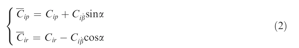
where i=l,n; Clis the rolling moment coefficient; Cnis the yawing moment coefficient; Ci0is the coefficients at zero sideslip; Ciβis the static stability derivatives;andare the nondimensional angular rate; Ciωais the rotation rate derivative andis the non-dimensional rotation rate around the velocity vector;andare the damping derivatives and cross derivatives, which are obtained from single degree-offreedom forced oscillations and are the combinations of pure rotation derivatives Cip,Cirand acceleration derivative.
The expression of Eq. (1) is commonly known as quasisteady model.
Fig. 1 shows the comparison between yaw-roll coupled experimental data and calculation results of the quasi-steady model at two typical angles of attack. In order to reveal more clearly the unsteady aerodynamic characteristics with respect to coupling ratio, only the dynamic increments (subtracting the static test data from the dynamic ones) of moment coefficients at zero sideslip when the sideslip angle varies from negative to positive are illustrated. Experimental results indicate that the aerodynamic coefficients in coupled motions were close to those in the pure yawing motion when η ≥10. Thus the yawing motion is expressed as η=10 in this paper. As is shown, the calculation results of quasi-steady model are well coincident with the experimental data at low angles of attack,but cannot reveal the complicated changes of damping characteristics (positive value of ΔClor negative value of ΔCnsignifies a negative damping, and vice versa) due to the strong coupling effects at high incidence.
In the past decades, mamy unsteady aerodynamic models have been proposed.27-29However, most of these investigations are based on the sample data obtained from the single degree of freedom forced oscillations, and the effects of yawroll coupling on the unsteady aerodynamic characteristics are commonly neglected. In order to reveal the coupling effects accurately,amodel was proposed based on the experimental data of yaw-roll coupled wind tunnel tests. The principle ofmodel is briefly illustrated in Fig. 2 and detailed in Ref.23. In the figure, subscript ‘‘b” means body axes and subscript ‘‘w”means wind axes,is the time rate of sideslip angle, V is the total velocity, Ω is the total angular velocity vector, ωaand F are the decompositions of Ω.
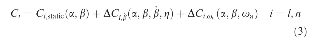
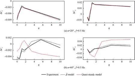
Fig. 1 Comparison between experimental data and calculation results of aerodynamic models.
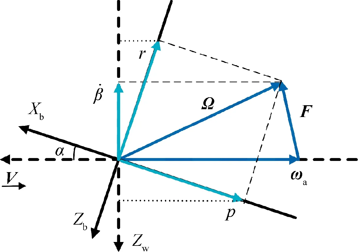
Fig. 2 Principle of model.

In the previous works of unsteady aerodynamic modeling,the investigations have been academic, and have not led to practical applications.27A significant reason is that they are difficultly compatible with the engineering approach in flight dynamic analysis. In order to apply the yaw-roll coupled experimental data into the engineering practices of departure prediction and restraint, which are all based on the concept of aerodynamic derivatives, themodel is than locally linearized at each coupling ratio.


3. Yaw-roll coupling effects on departure prediction
3.1. Prediction of departure behavior
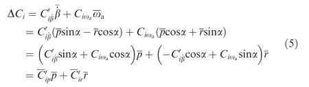
In the flight dynamics analysis, the linearized equations of motion are commonly used for departure prediction. As the influence of translational motion with small disturbance on the lateral-directional dynamic stability is negligibly small and the slight instability of long period spiral mode is considered to be acceptable30, thus the state equations of lateraldirectional motion(in open-loop configuration)can be simplified to the following form of third-order31
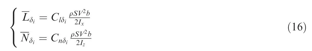
ρ is the atmospheric density, S is the wing area, b is the wing span, V is the total velocity, Ixand Izare the moments of inertia.
The characteristic equation of state matrix A can be written as

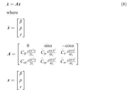
Then the coefficients b1, b2, and b3can be calculated and simplified as
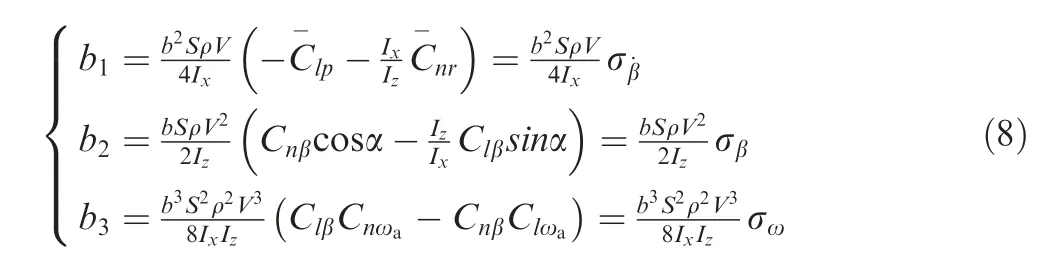


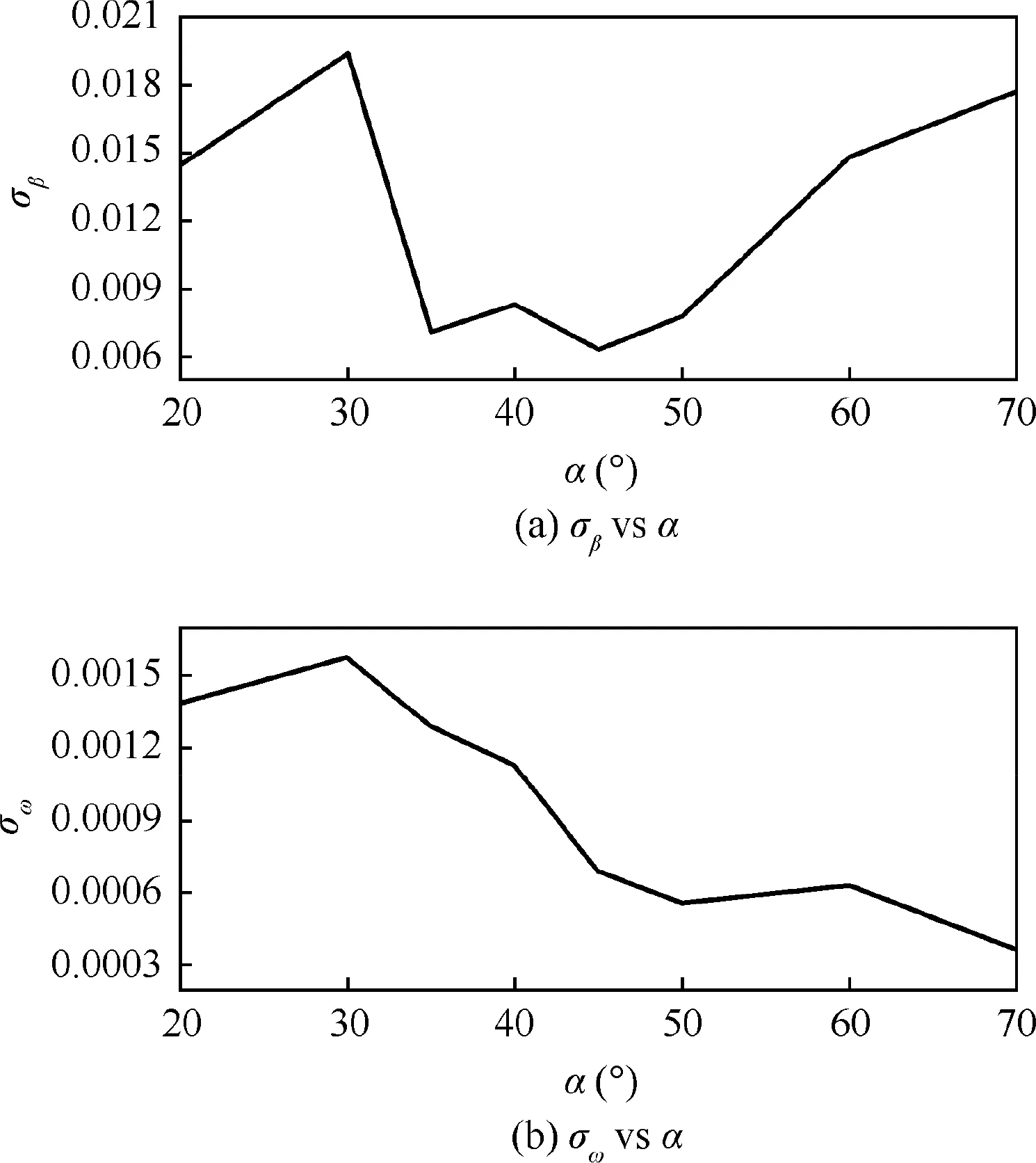
Fig. 3 Stability parameters σβ and σω.
As the parameters σβand σωhave nothing to do with the damping and cross derivatives, they are the same in the two prediction results based on conventional and nominal dynamic derivatives, as illustrated in Fig. 3. These two parameters are both positive.
Fig. 5 depicts the parametersand R calculated by the nominal dynamic derivatives obtained frommodel. The stability parameters show that the system is always stable when α ≤30°. When the angle of attack increases to 35°, an small unstable region appears around η=0.682. With the further increasing of α up to 50°, the unstable range of coupling ratio is more and more large. At higher angles of attack, the unstable range is gradually narrowing and is more close to yawing motion.
Furthermore, the conventional dynamic derivatives are obtained from pure rolling and yawing motions. The analyses of this two motions illustrated in Fig.5 indicate that there is no trend of departure, and are accorded with the prediction of conventional method. However, the loss of departure resistance in partial region of coupling ratio cannot be accurately revealed by existing engineering approach. Thus, the yaw-roll coupling effects are necessarily taken into the prediction of lateral-directional departure.
3.2. Flight simulations of departure behavior
In order to further verify the yaw-roll coupling effects on the lateral-directional departure characteristics, both quasisteady model andmodel are used for flight simulations. In the simulations, the full set of non-linear equations of aircraft motion in the body-axis system of 6-DoF are used. In a real flight, the departure behaviors may also be produced by the asymmetrical yawing moment, which appears under nonsideslip condition at high angles of attack. However, this kind of departure can be effectively restrained by a variety of approaches, as discussed previously. Thus this asymmetrical moment is ignored in the simulations. The actuator dynamics of control surfaces are also neglected. In all the simulations,the altitude is simply chosen as sea level.
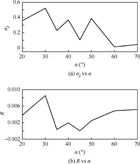
Fig.4 Stability parameters and R calculated by conventional aerodynamic derivatives.
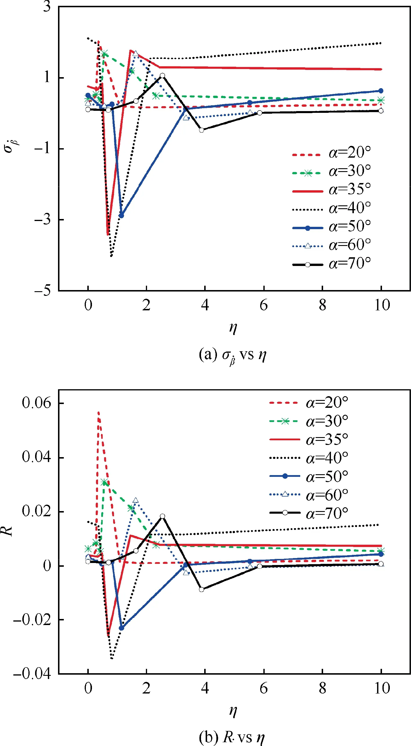
Fig. 5 Stability parameters and R calculated by model.
Since 35° is the critical angle of attack at which the departure behavior is first predicted bymodel, the simulation of straight and level flight at this incidence is conducted.The simulation results of bothmodel and quasi-steady model are shown in Fig.6.When the simulation is started,a small disturbance is given by deflecting the rudder to -2.5° for 0.2 s. The results ofmodel show that the aircraft enters a departure behavior after the disturbance. The results of quasi-steady model show that a slight lateral-directional oscillation is induced by the disturbance but disappears quickly.
As illustrated in Fig. 5, there is only one set of dynamic experiments (η=0.682) in the unstable region of coupling ratio at α=35°. The unstable experimental data at this coupling ratio are therefore removed from the sample data ofmodel. The other aerodynamic forces and moments are unchanged. The simulation results are also illustrated in Fig. 6, showing almost the same behavior with the results of quasi-steady model. Thus, the yaw-roll coupling ratio is an important parameter in the analysis of departure susceptibility and flight simulations.
4. Yaw-roll coupling effects on departure restraint
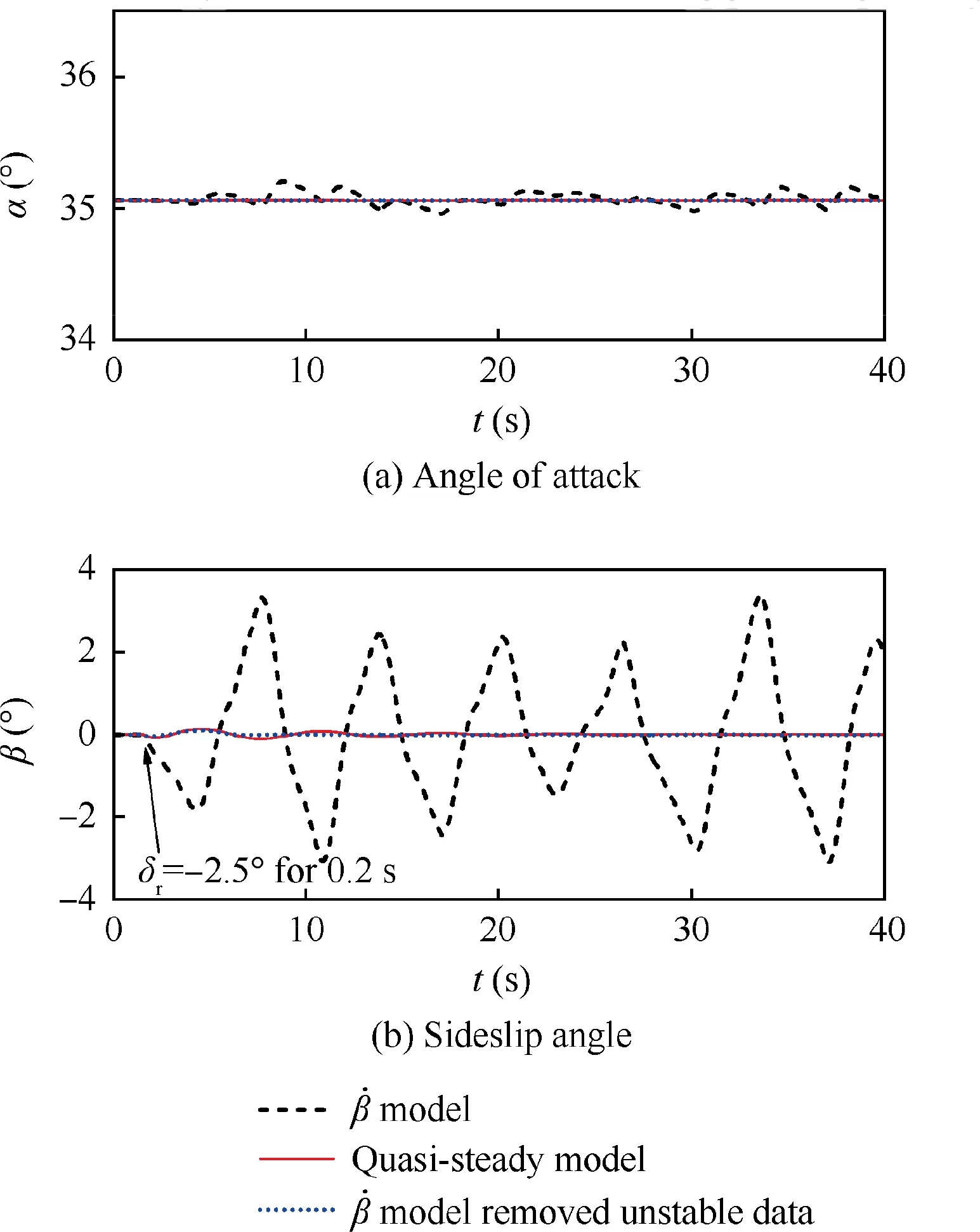
Fig. 6 Simulation results of straight and level flight at α=35°.
The maneuverability at high angles of attack is emphasized for an air-superiority fighter.It is necessary for the aircraft to have sufficient control power and stability to prevent unwanted departure from the controlled flight, especially in the flight regime beyond standard flight envelope. The stability control law in post-stall region is the interest of many researchers.
In the past studies,the yaw-roll coupling effects have never been considered in the design of lateral-directional SAS. As demonstrated above, the yaw-roll coupling ratio plays an important role in departure susceptibility. In this section, a simple SAS with fixed-gain is designed to investigate the effects of yaw-roll coupling ratio on departure restraint.The feedback gains are separately obtained from conventional and nominal dynamic derivatives, using pole-placement method.
4.1. Design of lateral-directional SAS
4.1.1. Pole-placement method
For the purpose of the design of feedback gains,the simplified three-order equations of motion with control are used

The state matrix A,control efficiency matrix B and control input u are expressed as
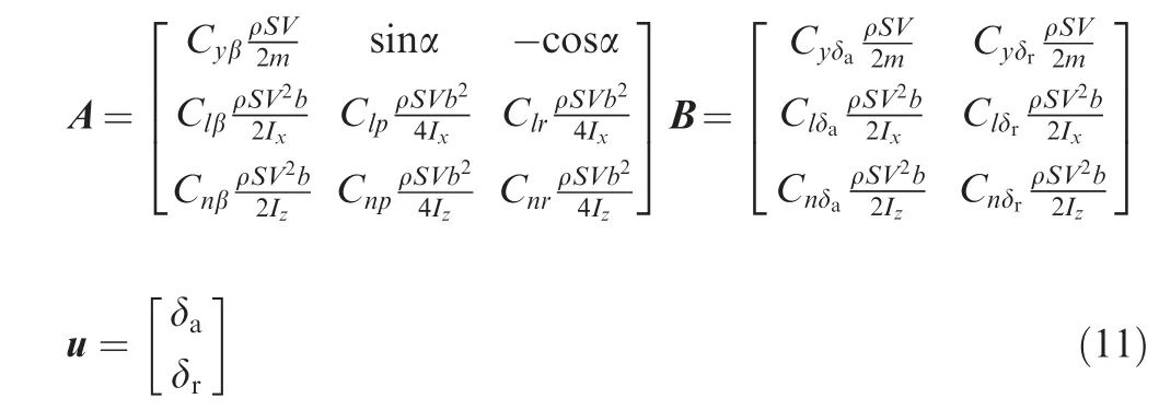
where m is the mass of aircraft;Cyδa,Clδaand Cnδaare the control efficiencies of aileron; Cyδr, Clδrand Cnδrare the control efficiencies of rudder; δaand δrare the deflections of aileron and rudder, respectively.
The eigenvalue distribution of matrix A may result in that the dynamic response of open-loop system cannot meet the requirements of flying quality or even the dynamic stability.Thus a feedback loop(SAS)is required to improve the stability of close-loop system. The control input of SAS (u′) can be expressed by a matrix of feedback gain K
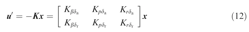
where Kβδi, Kpδiand Krδi(i=a, r) are the feedback gains of aileron and rudder with respect to sideslip angle, roll rate and yaw rate, respectively.
Adding Eq.(12) into Eq. (10), the state equations of closeloop system with stability augmentation can be obtained:

where Accan be considered as the state matrix of the closeloop system. Fig. 7 shows the block diagram.
Assuming that f(λ*) is the desired eigenpolynomial of the close-loop system which meets the design requirements, the feedback gain matrix K can be calculated by

4.1.2. Calculation of feedback gains
As discussed previously, nominal dynamic derivatives can be transformed from the yaw-roll coupled experimental data by linearizedmodel. Thus, the characteristic roots of each yaw-roll coupled motion can be calculated.Because the unstable region of coupling ratio at α=35°is small and there is only one experimental coupling ratio in this region, the experimental data at α=40°which has a larger unstable range are used as an example. The eigenvalues of open-loop system at each experimental coupling ratio are listed in Table 1, and the calculation results of conventional aerodynamic derivatives are also given.
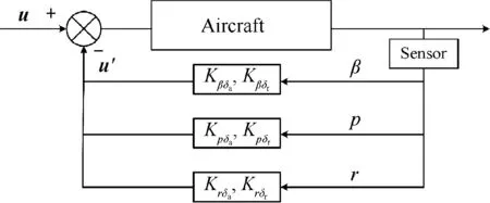
Fig. 7 Block diagram of SAS.
In the calculation results of conventional aerodynamic derivatives,the real root which indicates roll mode and the real parts of the pair of complex conjugate roots which indicate Dutch-roll mode are all negative. In the results calculated by nominal dynamic derivatives, positive eigenvalues appear at η=0.578 and 0.814. Moreover, the complex conjugate roots all degenerate into real roots and the characteristics of modes are obscure.

It is evident from Fig. 8 that the characteristic roots of the two unstable coupling ratios are very close, and so do the eigenvalues of the five stable coupling ratios. Thus, the nominal dynamic derivatives at stable and unstable coupling ratios are separately averaged to calculate the feedback gains.A twosegment SAS according to the stable and unstable regions of coupling ratio are therefore obtained. The feedback gain matrices of the two-segment SAS and the matrix calculated by conventional aerodynamic derivatives are listed in Table 2.The SAS at other angles of attack can be obtained by the same approach.
If the matrix K is used in the stable region of coupling ratio,the characteristic roots of the close-loop system are λ1,2=-1.17±2.179i and λ3=-2.53. The system is stable and has a better flying quality. However, if K is used in the unstable region, the real characteristic roots are λ1=6.76,λ2=0.82 and λ3=-1.94, the system is unstable either. Similarly, if the matrix K1calculated by the experimental data of stable region is used in the unstable region, the characteristic roots are changed to λ1,2=2.82±1.254i and λ3=-2.35, the Dutch-roll mode is unstable.
It is thus clear that the yaw-roll coupling ratio has a great influence on the short-period modes. The segmented design of feedback gains in accordance with the dynamic analysis of departure at different coupling ratios is necessary. So that the departure resistance can be guaranteed in the maneuvers at high angles of attack.
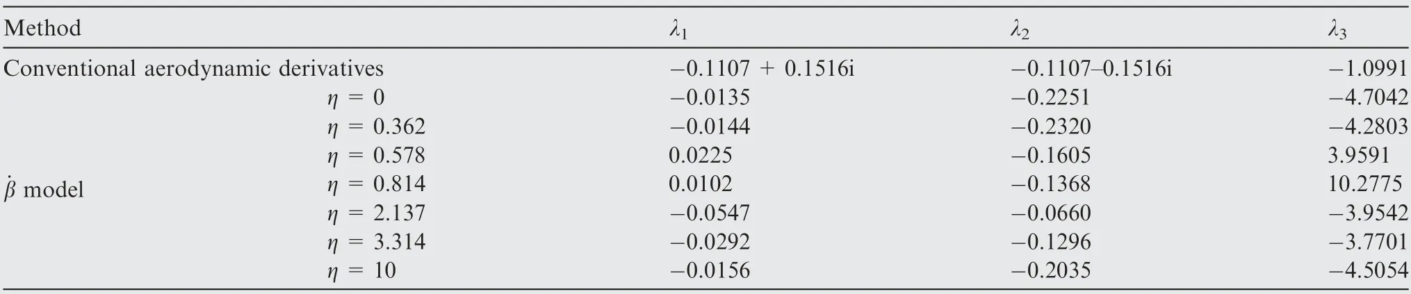
Table 1 Eigenvalues of open-loop system at α=40°
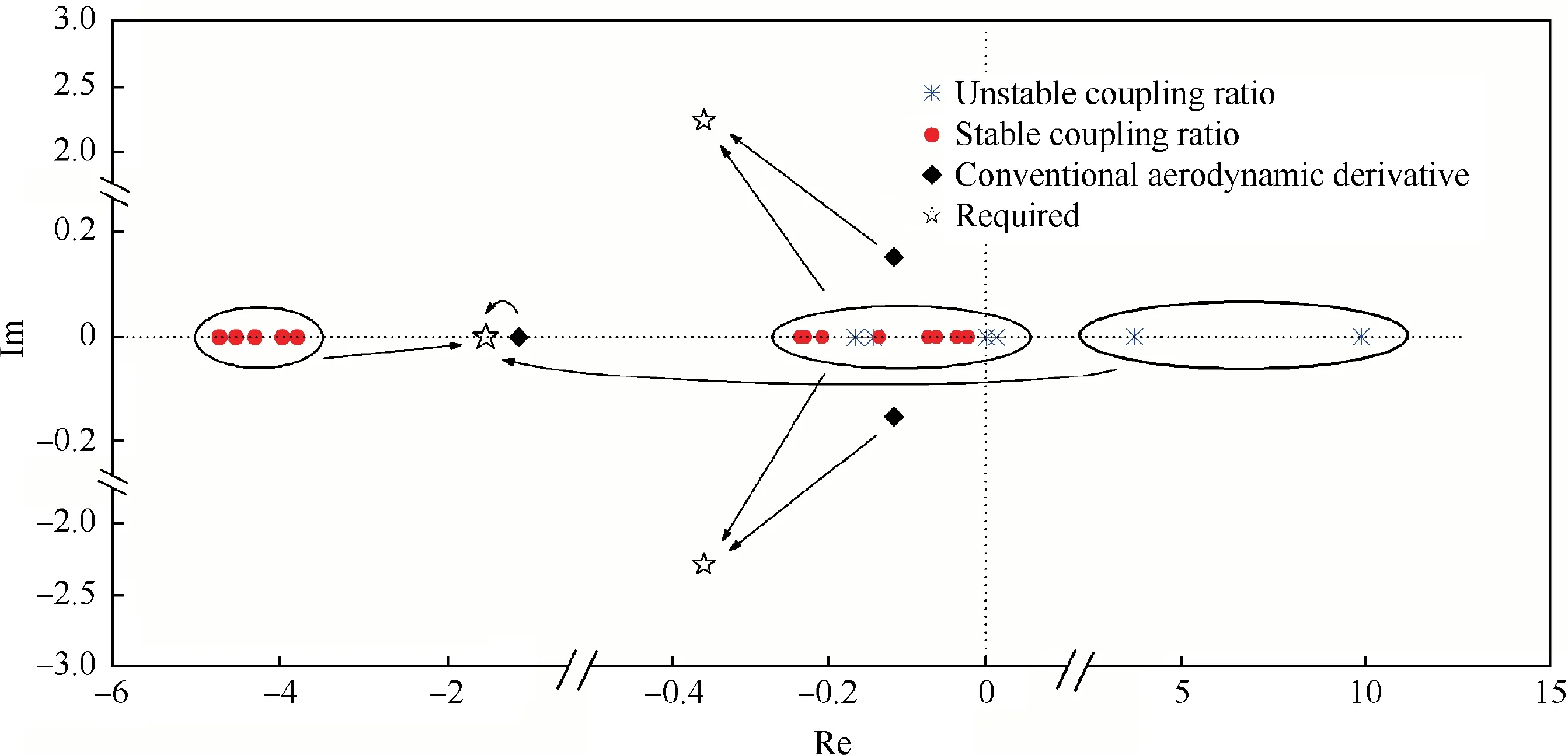
Fig. 8 Process of pole placement.
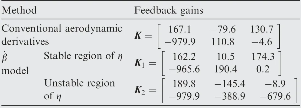
Table 2 Feedback gain matrices calculated by different methods (α=40°).
4.2. Assessment of two-segment SAS
In order to evaluate the effectiveness of the two-segment SAS,flight simulations at different angles of attack are carried out in this section. The aerodynamic model is selected asmodel,sincemodel can more accurately reveal the departure characteristics with respect to yaw-roll coupling than the quasi-steady model.
4.2.1. Straight and level flight at α=40°
The simulation results of open-loop configuration are illustrated in Fig. 9. The unstable region of coupling ratio is η ∈[0 .4, 1.8].
The flight is started with a straight and level flight at α=40°. When a disturbance is given, the aircraft enters a departure behavior of‘‘wing rock”which is much more drastic than that at α=35°.The amplitude of sideslip angle is steadily increasing and is finally upon ±6°.
Two cycles of the steady stage of self-oscillation are locally amplified in Fig.10.As illustrated,when the fighter enters into the unstable region of coupling ratio,the departure is occurred and the sideslip angle is divergent.With the development of the motion, the coupling ratio is out of the unstable region, the sideslip angle is therefore decreased by the stable dynamic characteristics. However, the coupling ratio re-enters the unstable region with the action of aerodynamic damping.Over and over, the aircraft is oscillated within a limited amplitude.
Then, the SAS obtained from the conventional aerodynamic derivatives is added into the open-loop simulation.The simulation results are shown in Fig.11.It can be observed that the maximum amplitude of sideslip angle is decreased to±1.5°. In the steady oscillation stage, the rudder is saturated.
The details of an enlarged scale and the lateral-directional aerodynamic moments respectively generated by airframe and control surfaces are shown in Fig. 12. When the aircraft is flying in and out of the unstable region, the aerodynamic moments produced by airframe are dramatically changed.However, the control surfaces cannot respond to the transient variations of the aerodynamic moments in time. The aerodynamic moments produced by control surfaces are much larger than those produced by airframe, especially the yawing moments. Although the responses of control surfaces are not in the correct manner, the time of the aircraft crossing the unstable region is significantly reduced. Thus, the departure behavior is restrained finitely,but not eliminated completely.It is commonly considered that the rudder efficiency is diminished in high-α regime due to the influence of fuselage and wing wake on vertical tail surface, so that the flying quality cannot be satisfied. Thus, the Thrust Vector Control (TVC)is required to enhance the control efficiency.
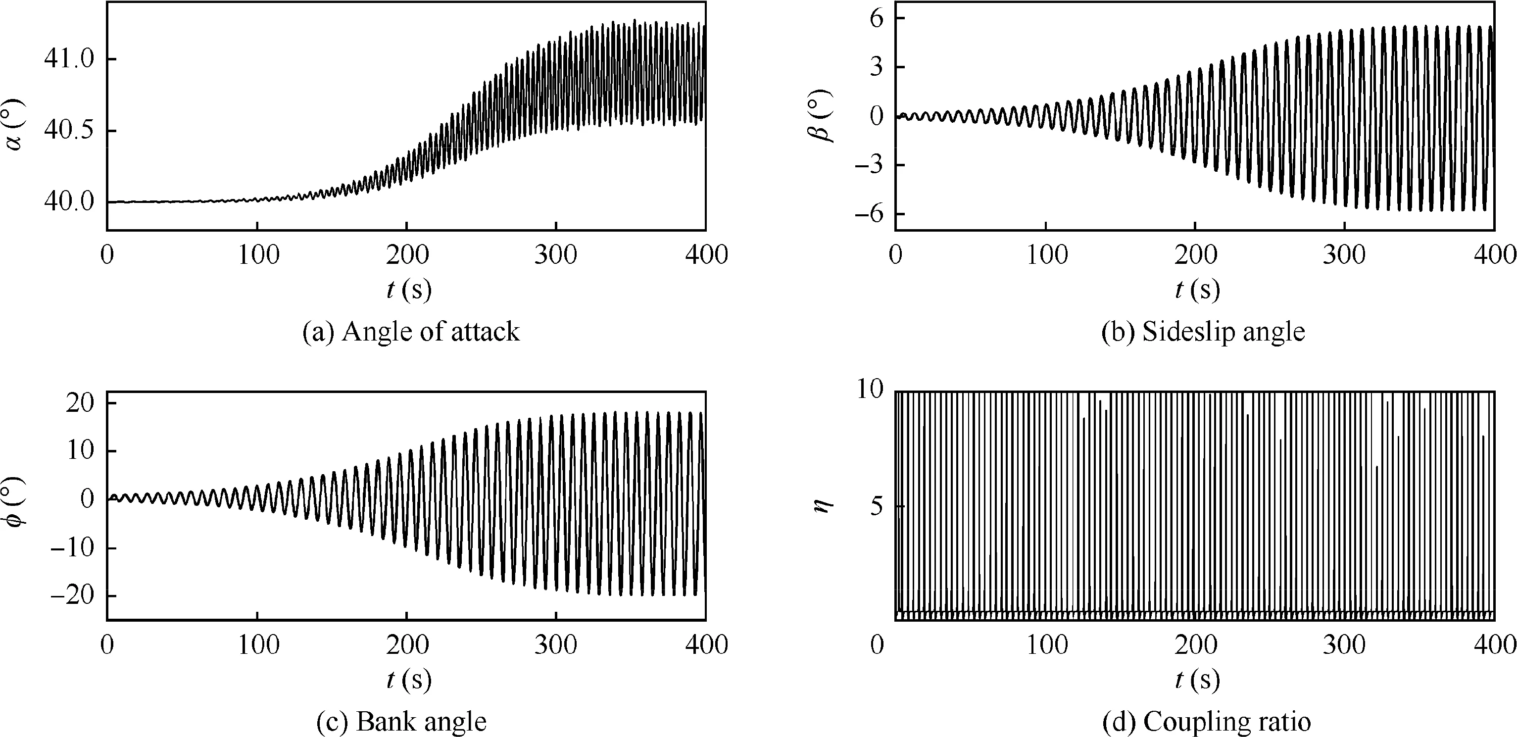
Fig. 9 Simulation results of open-loop configuration at α=40°.
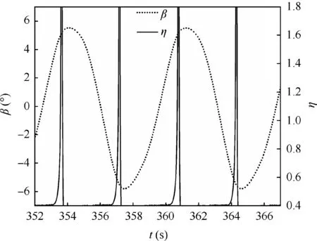
Fig. 10 Amplification of steady oscillations.
Because the investigated fighter is not a TVC aircraft, the control derivatives of rudder and aileron are simply magnified to simulate the enhanced effects of TVC on the control power.Fig. 13 shows the performance of the conventional SAS with enhanced control efficiency in the departure behavior. The control derivatives are magnified to 8 times.
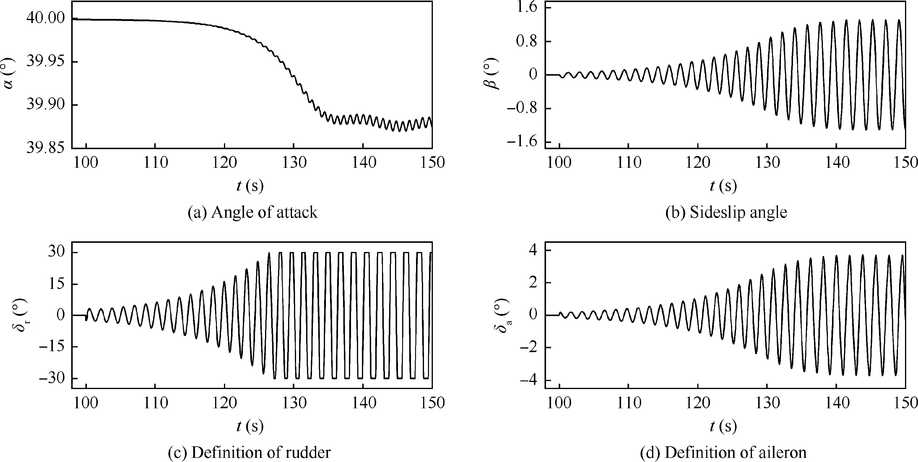
Fig. 11 Performance of conventional SAS at α=40°.
As illustrated, the amplitude of sideslip angle is reduced within±0.05°.It is generally recognized that the flying quality can provide a comfortable handing for pilot when the oscillation of sideslip angle is within 0.1° under a small disturbance.Thus the simulation results represent an excellent flying quality. Because of the enhanced control power, the duration of coupling ratio in the unstable region is much shorter than that without TVC. Thus, the deflections of control surfaces are much smaller, and the aerodynamic moments produced by control surfaces are reduced greatly. It seems that the conventional SAS with TVC works very well on the departure restraint. However, the responses of control surfaces are still not in the correct manner, and the yawing moment coefficient produced by control surfaces is also much larger than that produced by airframe.
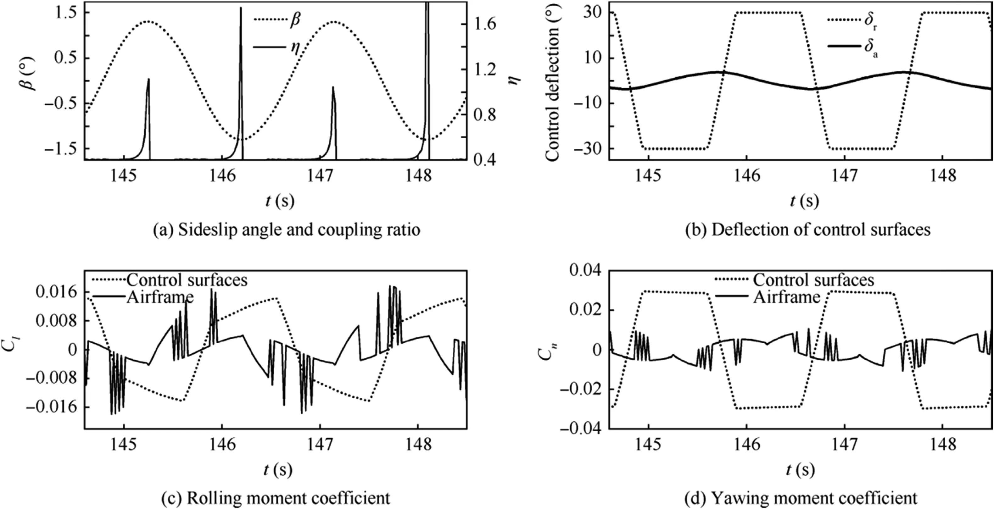
Fig. 12 Enlarged scale of simulation with conventional SAS.
Fig. 14 shows the simulation results of two-segment SAS without the assist of TVC, as well as the aerodynamic moments produced by airframe and control surfaces respectively. With the same disturbance, the maximum amplitude of sideslip angle is smaller than-0.06°which is similar to that in Fig.13.However,the convergence trend of the sideslip angle is much more obvious with the action of two-segment SAS.Moreover, the deflections of aileron and rudder are quite small. When the fighter enters the unstable region, the control surfaces quickly respond to the variation of coupling ratio which can be clearly observed at t ≈14.5 s. The aerodynamic moments separately produced by control surfaces and airframe are identical in the order of magnitude, and are much smaller than those in Fig. 13. With considering the effects of yaw-roll coupling ratio on the departure susceptibility,the two-segment SAS is much more effective than the conventional SAS. The natural control efficiency is sufficient to provide the demanded stability.
4.2.2. Steady turn at α=40°
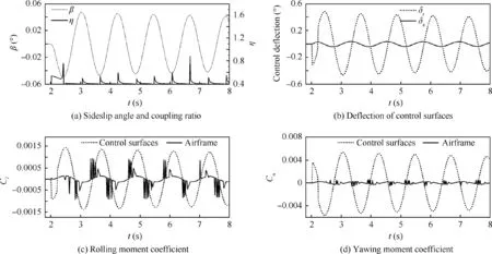
Fig. 13 Action of conventional SAS on departure restraint with TVC.
In the simulation of the straight and level flight, the twosegment SAS shows effective restraint of the departure behavior. In this section, the performance of the two-segment SAS is evaluated by the simulations of steady turn.
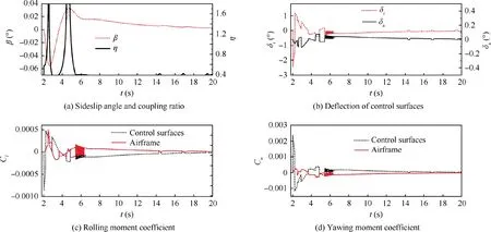
Fig. 14 Performance of two-segment SAS at α=40°.
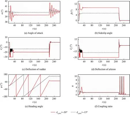
Fig. 15 Steady turn with two-segment SAS at α=40°.
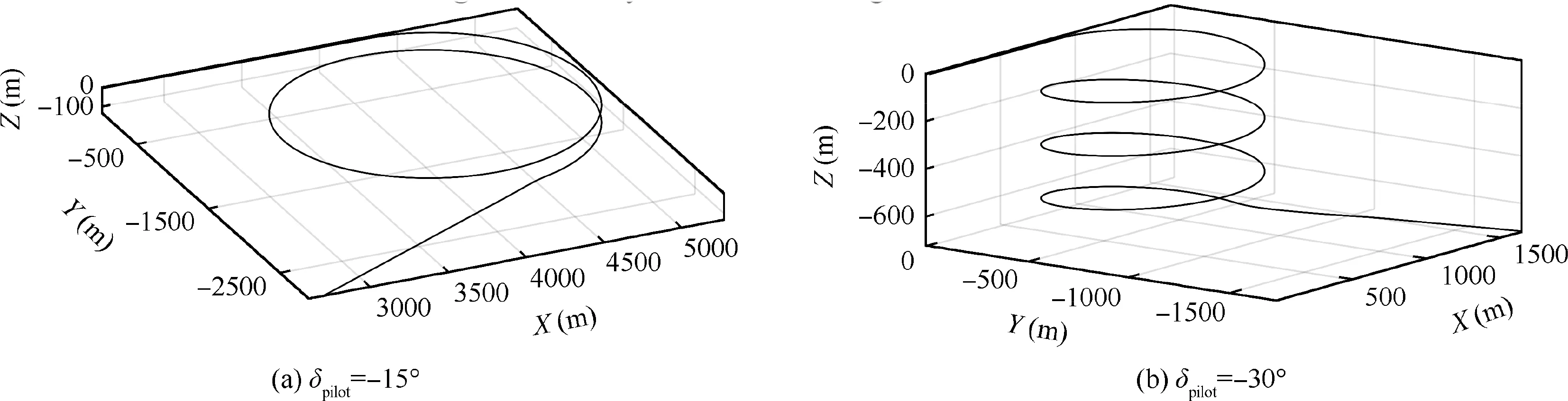
Fig. 16 Trajectory of steady turn with two-segment SAS.
The commands of the pilot are set as deflecting the aileron to-15°and-30°,respectively.The simulation results of twosegment SAS are illustrated in Fig. 15 and the flight trajectories are shown in Fig.16.Because of the decreasing of the control efficiency, the turning radiuses are large. With the increasing of control deflection manipulated by pilot,the turning radius and period are accordingly decreased.Although the coupling ratio within the steady turn stage is in the unstable region, the departure behavior is effectively restrained. Since there is no control system in longitudinal direction and the thrust is set as invariable, the altitude is inevitably decreasing.It is acceptable because of the small descent rate. When the pilot commands are cancelled,the aircraft is rapidly recovered to a straight and level flight.
Fig. 17 shows the simulation results of the conventional SAS without TVC and its trajectory is shown in Fig.18.When the pilot command of δa,pilot=-15°is inputted, the aircraft enters into a spin. During the spin, the rudder is saturated again. The period of spin is about 18 s and the radius of spin is 220 m. Within each cycle, the altitude loss is about 800 m.Obviously, the conventional SAS has not played a due role.
4.2.3. Herbst maneuver
The Herbst maneuver is one of the most complicated post-stall maneuvers for a high agility fighter. In the maneuver, the aircraft is first pulled up until the angle of attack reaches at the range from 50° to 70°. Then, the nose pointing is made a Uturn in seconds. In order to reduce the divergent of sideslip angle in the maneuver, the Aileron-Rudder Interconnect(ARI) is used to made the aircraft rotate around the velocity vector (η=tanα). The pilot commands of rudder and aileron are interconnected by the coefficient KAPI
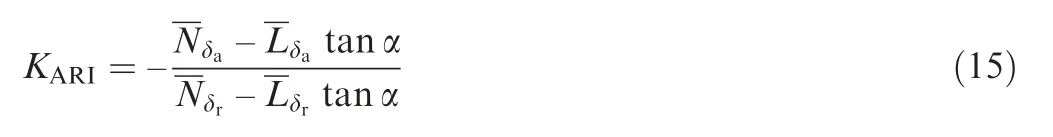
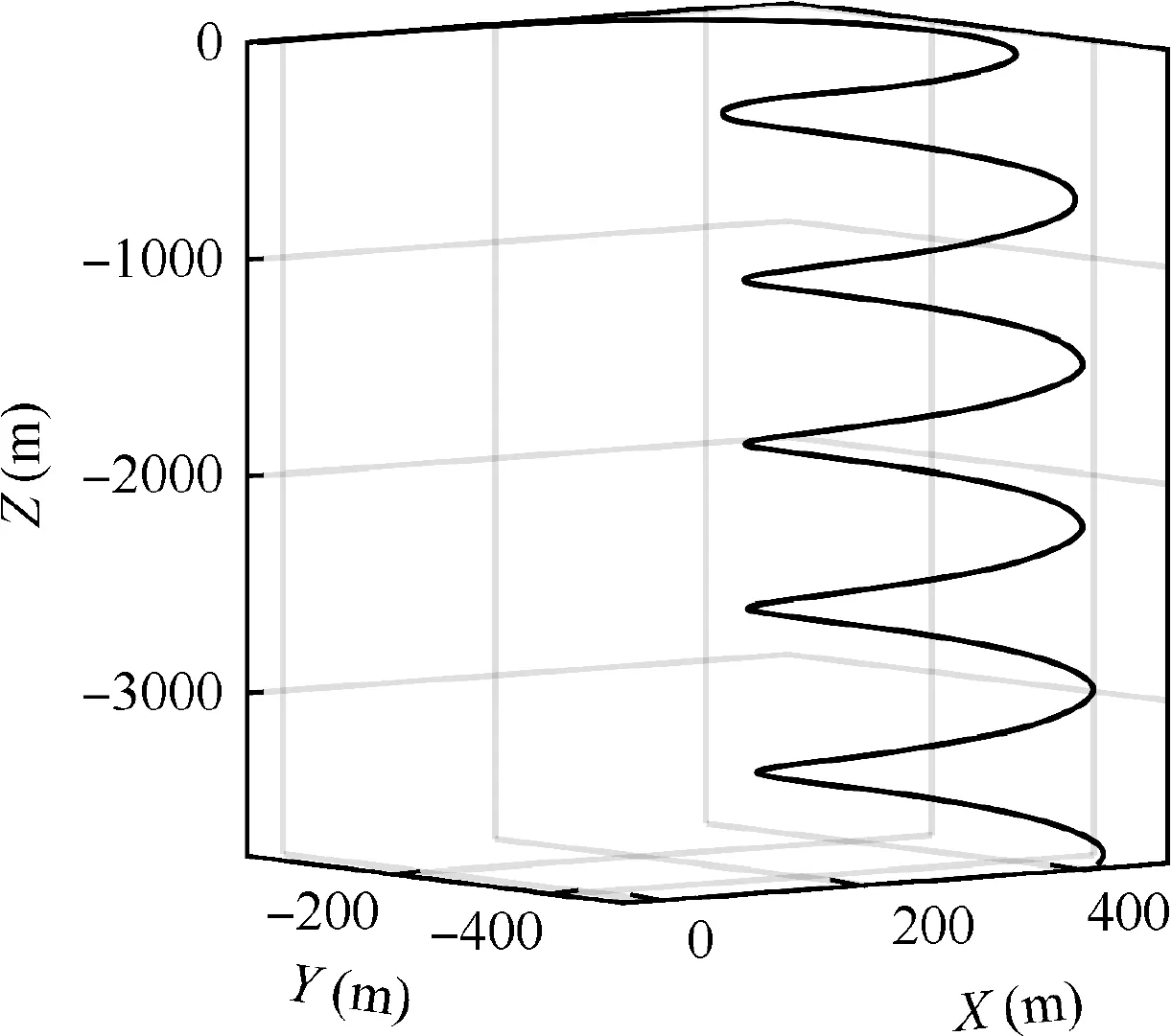
Fig. 18 Trajectory of steady turn with conventional SAS.
where
In the simulation,when the pilot command of aileron δa,pilotis given, the command of rudder can be automatically obtained by δr,pilot=KAPIδa,pilot.
As illustrated in Fig.5,η=tanα is in the stable range when angles of attack are higher than 50°. Thus the simulation of Herbst maneuver is conducted at α=50°to compare the difference between the performance of conventional SAS and two-segment SAS in post-stall maneuvers.In order to simplify the process of simulation, the simulation is started with a straight and level flight at α=50°, and the rapid turn is conducted directly.
As the efficiency of rudder is greatly reduced at such a high angle of attack, the assist of TVC is needed in the simulations of both the conventional SAS and two-segment SAS. Similarly, the efficiencies of rudder and aileron are magnified directly to simulate the effects of TVC. After repeated attempts, the amplification factor of the control derivatives should be set as 8 in the conventional SAS and 4 in the twosegment SAS, thus the Herbst maneuver can be completed.The simulation results are shown in Fig. 19.
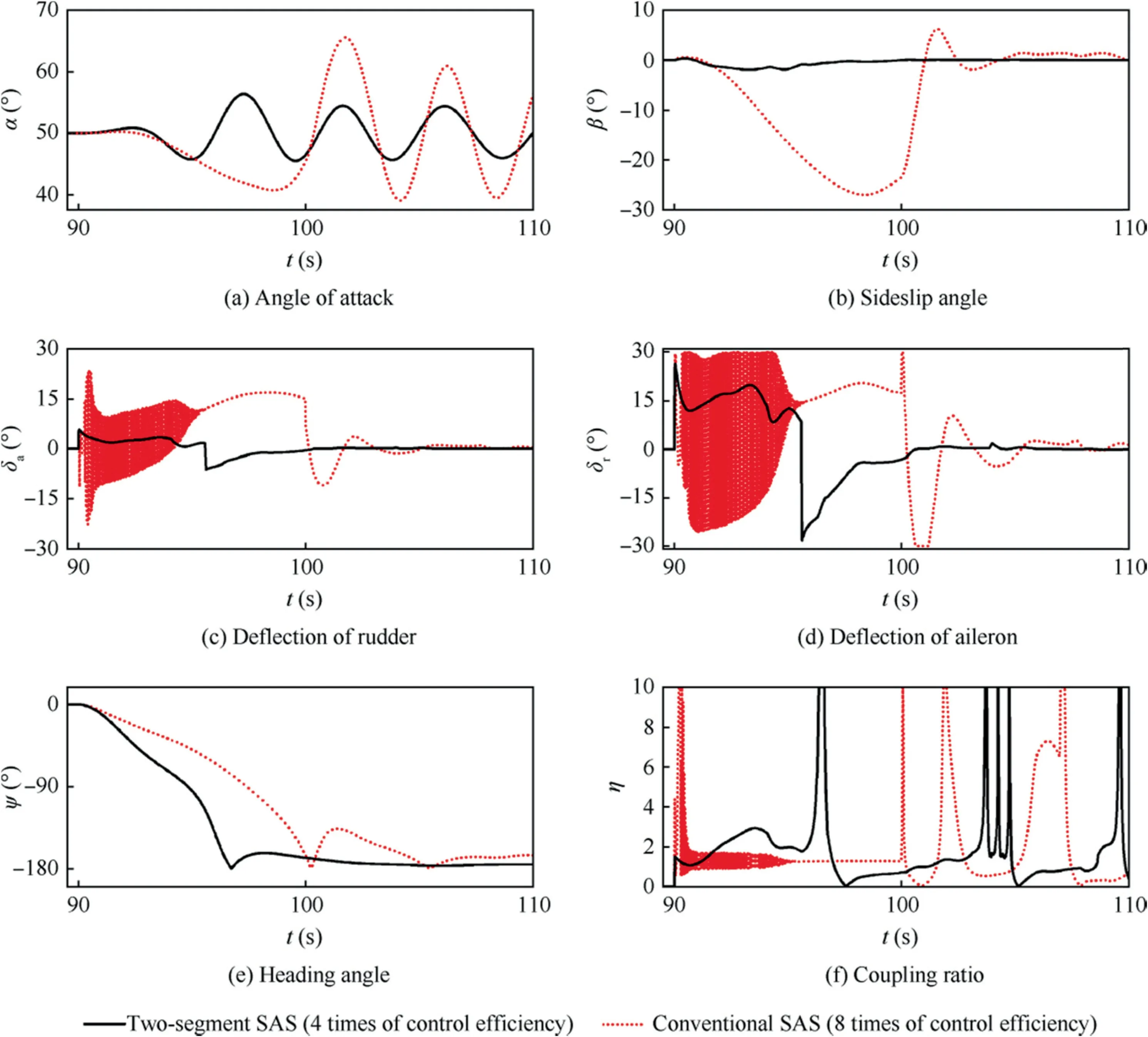
Fig. 19 Simulations of Herbst maneuver.
The simulation of conventional SAS shows that the maneuver is completed in 10 s. In the first half of the maneuver, the coupling ratio is kept in the unstable range for a long time.As discussed above,the conventional SAS cannot respond correctly in the unstable region of coupling ratio.Thus the control surfaces are deflected quickly and sharply to keep the aircraft in an unstable state, the rudder is saturated of positive deflection. In the second half of the simulation, the aircraft is oscillated dramatically in longitudinal direction.As the parameters in Eq.(15)are simply set as those at α=50°,the oscillations of control surfaces are alleviated when the angle of attack is far away from 50°. Even so, the sideslip angle in the simulation is divergent and the maximum is up to-28°.It is unacceptable in real flight.
With the action of the two-segment SAS, the maneuver is completed well. The coupling ratio is not strictly coincident with η=tanα due to the conflict between the commands separately given by pilot and SAS.However,the amplitude of sideslip angle is within±2°.The Herbst maneuver is completed in 7 s, and no obvious departure behavior is observed. Although the TVC is also needed in this simulation,the magnification of the control efficiency is only half of the conventional SAS,and the deflections of control surfaces are much smaller. It implies that the thrust loss due to the deflection of vectoring nozzle based on the two-segment SAS is much less than that of conventional SAS.
4.2.4. Spin recovery at α=60°
In the studies of the aerodynamic characteristics of an aircraft at high angles of attack, the recovery of spin is an important area of research.In this section,the performance of the different SASs on auto-recovery from the spin is assessed.When the angle of attack is larger than 50°, a nose-down pitching moment is obvious due to the design requirements. Thus, the efficiency of elevator is artificially enhanced to trim the aircraft in longitudinal direction at α=60°.It will not affect the assessment of the lateral-directional SAS.
The simulation is first carried out in the open-loop condition and started with a level flight at α=60°. At such a high angle of attack,the unstable region of coupling ration is large.Thus the aircraft enters into a spin. At the stable oscillation stage of the spin (t=160 s), the SAS is incorporated into the simulation.Similarly,the control efficiency should be magnified to 4 times in both of the two SASs. The simulation results are illustrated in Fig. 20.
When the two-segment SAS is incorporated into the system, the control surfaces are dramatically deflected in a short time. In fact, the enhancement of control efficiency is merely required on this moment. Then the aircraft recovers from the spin and enters into a steady level flight. It should be noted that there is an unnoticeable left spiral in the level flight(heading angle changes very slowly), which indicates that the spiral mode is slightly unstable. It demonstrates that the negligence of spiral mode in this investigation is feasible. When the conventional SAS is added into the simulation,the aircraft recovers from the right-hand spin, but quickly enters into another departure behavior whose state is between left-hand spin and steep spiral.
As discussed above, the two-segment SAS shows a better performance on departure restraint than the SAS obtained from the conventional aerodynamic derivatives.In this investigation, the two-segment SAS is simply designed by the fixedgain separately obtained from the stable and unstable regions of the coupling ratio. If the gain-scheduling method is used to make the feedback gains smoothly vary with coupling ratio and sideslip angle, the performance of the two-segment SAS will be more perfect.
5. Conclusions
The effects of yaw-roll coupling ratio on the lateral-directional departure prediction and restraint are investigated.The prediction of lateral-directional departure behavior based on the normal dynamic derivatives obtained from yaw-roll coupled experimental data is compared with the prediction of the existing engineering method which is based on the conventional aerodynamic derivatives. Then, a simple two-segment SAS is presented, with the consideration of the yaw-roll coupling effects on the departure feature. The simulations at different angles of attack are conducted, and the performances of the two-segment SAS and the conventional SAS are compared.It is concluded that:
(1) The conventional aerodynamic derivatives cannot reveal the variation of damping characteristics of lateraldirectional aerodynamic moments with coupling ratio.Thus the current engineering method based on the conventional aerodynamic derivatives can neither predict the departure susceptibility accurately, nor fully reveal the departure behavior in flight simulation.
(2) As the yaw-roll coupling ratio has a great influence on the lateral-directional aerodynamic damping characteristics, the departure prediction based on the yaw-roll coupled experimental data can accurately indicate the angles of attack at which the departure may appear.Moreover, it also indicates that the departure resistance will loss in partial region of the coupling ratio, rather than all the motion states.
(3) Based on the yaw-roll coupled experimental data,a twosegment stability augmentation system with two different matrices of feedback gains respectively according to the stable and unsteady regions of coupling ratio is obtained. The simulations of straight and level flight,steady turn, spin recovery and Herbst maneuver show that the two-segment SAS has a better performance than the SAS obtained from conventional aerodynamic derivatives. By using the two-segment SAS, the departure behavior can be restrained by less control energy but in a better flying quality than the conventional SAS.
In summary,the yaw-roll coupling ratio is a key parameter in the analysis of departure susceptibility and design of the stability augmentation system at high angles of attack. Thus it is necessary for an air-superiority fighter to obtain the aerodynamic data from yaw-roll coupled wind tunnel tests.
Acknowledgement
This work was supported by the National Natural Science Foundation of China (No. 11872209).
 CHINESE JOURNAL OF AERONAUTICS2019年10期
- CHINESE JOURNAL OF AERONAUTICS的其它文章
- Design and analysis of a hypersonic inlet with an integrated bump/forebody
- Experimental study of effect of post processing on fracture toughness and fatigue crack growth performance of selective laser melting Ti-6Al-4V
- Efficient and accurate online estimation algorithm for zero-effort-miss and time-to-go based on data driven method
- Experimental and numerical investigation of threedimensional vortex structures of a pitching airfoil at a transitional Reynolds number
- A methodology for simulating 2D shock-induced dynamic stall at flight test-based fluctuating freestream
- Robust adaptive compensation control for unmanned autonomous helicopter with input saturation and actuator faults