Topology-optimization of Lens Contact Support Structures: PV Value as An Optimization Objective
LI Yi-mang, ZHOU Zi-yun, LIU Yong-ming
(1. School of Mechanical Engineering, Changzhou University, Changzhou 213164, China; 2. School of Mechanical and Automotive Engineering, Anhui Polytechnic University, Wuhu 241000, China)
Abstract: The contact position, contact area, contact stress and flexibility of single lens support structure in an optical system are important influencing factors of the system’s imaging quality. Topology optimization of the single-lens contact support structure is carried out using the aberration index PV value as the optimization objective to reduce geometric aberration aberration in the single mirror caused by gravitational force. We first establish the contact topology optimization model, then use a linear elastic structure in unilateral contact with a rigid support as-modeled by Signorini’s contact conditions as an example to verify the model. The aberration index PV value of the lens is described as a function of lens deformation; thus, the value serves as a functional objective of the topology optimization model. We use the SIMP method to describe the topology optimization design variables, and the augmented Lagrange multiplier method to solve the contact condition. The optimal solution of the topology optimization model can be solved via MMA optimization algorithm. The optimal topological configuration of supporting structures that satisfy geometric aberration requirements is defined by the optimal solution of the design variables. We found that the PV value of the lens can be reduced by 14% and the lens surface RMS value by 13.8% after applying the proposed method. We also tested the lens PV value and RMS value on an experimental platform supported by the optimal contact support structure. The surface of the plane mirror surface PV values decreased by 60.4% and 42.9%, and the RMS values by 74.3% and 38.9%. To this effect, the optimal contact support structure effectively improves the precision of the single lens support and demonstrates significant potential for practical application.
Key words: topology optimization; optomechanics; mirrors analysis; optical machanical structure
1 Introduction
Optics is a classic discipline as well as a very popular modern research subject[1-3]. Optics helps us to better understand the environment of outer space and explore our own world down to the nanometer level. Advancements in optical technology have brought about increasingly stringent requirements for the precision of single lenses[4]. For example, consider the 193 nm lithography projector which has objective accuracy of 1-2 nm RMS; its components must be engineered with remarkable precision to achieve such accuracy[5-6].
The precision single lens and its supporting technology play an important role in the optical system. However, a general lack of effective support structure designs yet hinders the further development of precision single lenses. The purpose of structural design is to select those design variables which most effectively optimize the performance of the structure, so the structural design problem can be attributed to an optimization problem[7-9]. Commonly used structural optimization techniques include size optimization, shape optimization, free size optimization, free shape optimization, topographical optimization, and topological optimization. Topological optimization is conducted to identify the optimal topology of the structure at the conceptual design stage; it is significantly more efficient than the traditional shape or size optimization processes[10-13].
Topology optimization design was the focus of the present study. We first established a contact topology optimization model, then used a linear elastic structure in unilateral contact with a rigid support as-modeled by Signorini’s contact conditions as an example to verify its correctness. Based on the model, the aberration index PV value of the lens can be described as a function of the lens deformation. We also used the SIMP method to describe the topology optimization design variables, and the augmented Lagrange multiplier method to solve the contact condition. We obtained the optimal solution to the topology optimization modelviaMMA optimization algorithm. The optimal topological configuration of supporting structures that satisfy geometric aberration requirements can be defined by the optimal solution of topological optimization design variables. We analyzed the topological optimization results in detail, then established an experimental platform for the sake of further assessment. The lens PV value and RMS value were tested as-supported by the optimal contact support structure[22-27].
This paper is organized as follows. The precision single lens and relevant supporting technology are discussed in Section 2. In Section 3, the contact topology optimization model and PV minimum topology optimization model are established. Section 4 presents our simulation results. Section 5 describes our experimental setup for precision single lens support and the results of our model verification.
2 Precision Single Lens and Supporting Technology
The objective lens of a 193 nm mask alignment system is shown in Fig.1. It is mainly composed of a lithography mask, silicon wafer, and projection lithography lenses. A light beam is irradiated onto the silicon wafer through the projection lithography lenses.
The increasing integration of integrated circuit devices and device operating speed have created increasingly stringent requirements for manufacturing lithography projector projection objective lens resolution. Current projection lithography projection objectives include not only the application of large numerical apertures and short wavelength technologies, but also the use of improved lithography resolution wavefront engineering technology to ultimately enhance the lithography resolution. Aberration in the lithographic projection lens markedly influences the quality of the lithography. By design, the entire objective lens from 20 to 30 lenses has system wavefront requirements less than 10 nm. After tolerance distribution is established to meet the design accuracy requirements (lens surface of 1-2 nm), there are very high demands for optical components of the processing and objective lens support.
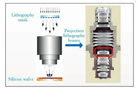
Fig.1 Objective lens of 193 nm mask alignment system
3 Optimization Mode Topology
Different boundary conditions correspond to different topologies and thus different topology optimization processes. Structural topological optimization must align with the actual physical boundary conditions. In a typical light machine, the metal support structure contacts the optical components which are fixed in the mirror. The characteristics of contact problems in this design include unequal inequality constraints with strong nonlinearity. It is difficult to solve contacting nonlinear topology optimization problems. To this effect, the topological optimization problem of contact nonlinear coupling structures and the design of optical machines is very significant in terms of practical application.
The equilibrium equation of the contact nonlinear finite element discrete form based on the Lagrange multiplier method can be written as follows:
(1)
[Kcλ]=[KcU]T,
(2)
(3)
(4)
whereNcis the interpolation of basis functions and the unit vector matrix,θis the overall coordinates to the local coordinate transformation matrix, [Kcλ] is the equivalent node contact force corresponding to the stiffness matrix, [KcU] is the displacement constraint stiffness matrix,Uis the displacement solution vector,PNis the Lagrange multiplier,Ris the equivalent node load, andgcis the contact gap.

(5)

You can read more about the history of the Christmas Tree, which was in use during Andersen s lifetime, on the Christmas Tree Farm Network and The Christmas Archives.
A contact topology optimization model with optical aberration PV value as the target is as follows:
(6)

(7)
(8)

(9)
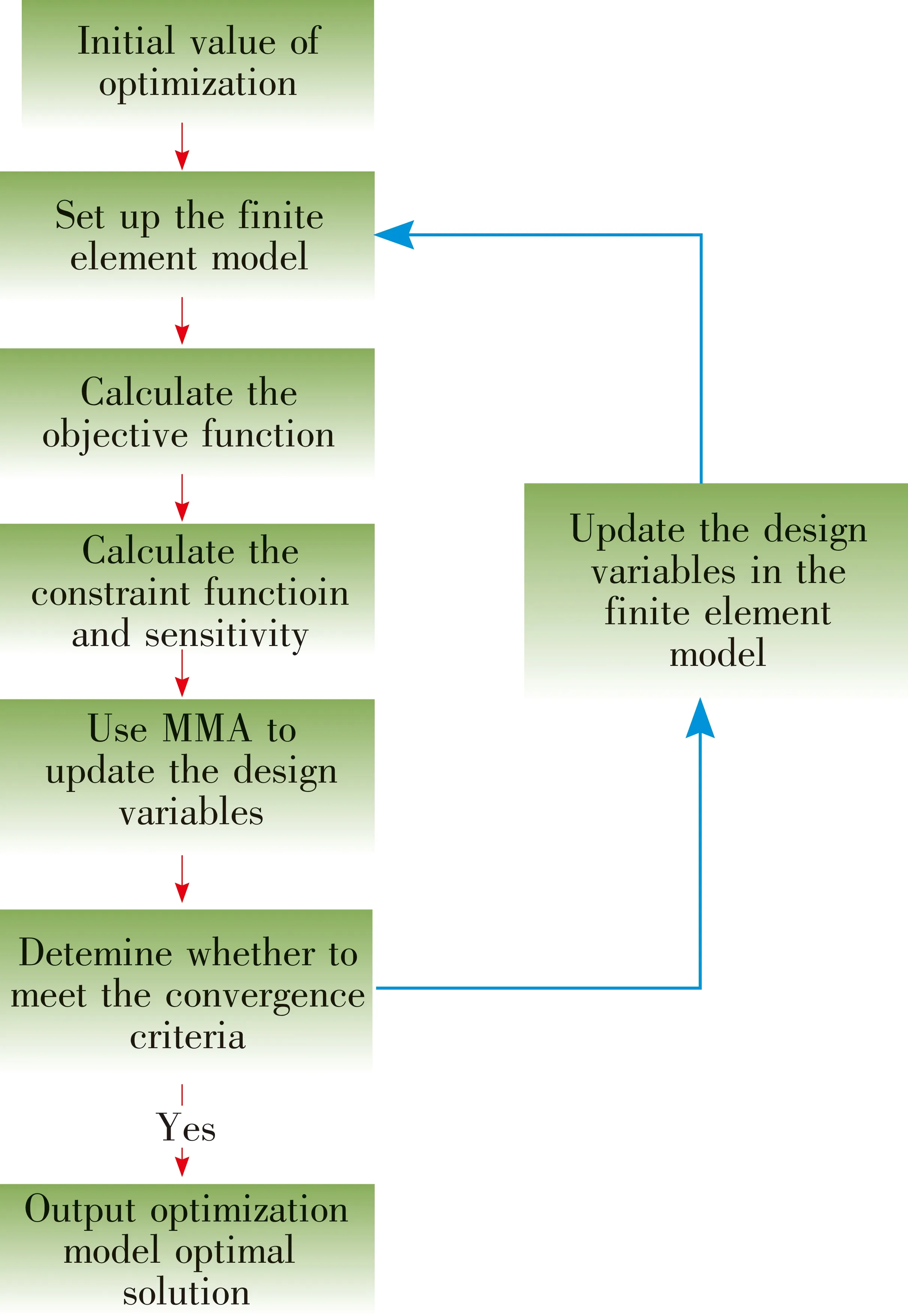
Fig.2 Program flow chart
We established the interpolation model using the improved SIMP method, the advantages of which include simple modeling, convenient solution, high computational efficiency, versatility, and portability. The interpolation model is as follows:
(10)

Here, we use the Lagrange multiplier method to construct the constrained optimization model. The Lagrange function is:
(11)
The derivative of the Lagrange function for optimizing the design variables is:
(12)
by Newton-Ranhson iteration, the following expression holds when the structural balance reaches convergence:
(13)
The tangent stiffness matrix of the solution can be rewritten as:
(14)
The derivative of the Lagrange function for optimizing the design variables is reduced to:
(15)
There is numerical instability inherent to the model above, but processing for sensitivity, density, and filtering method can effectively prevent it.
4 Simulation and Results
We next conducted a series of simulations to validate the model established above. First, we built a two-dimensional nonlinear topological optimization model with static strain energy as shown in Fig.3, where white areas are the optimization area and black areas are the rigid support section. The design area was optimized with boundary 1 as the contact boundary, rolling support at the lower left end, vertical downward force at the lower right end, size of 10 000 N, and the fixed area is marked in black. The Young’s modulus 2.1 e5 MPa and Poisson’s ratio is 0.3. The objective function is the minimum static strain energy.
In Fig.4, the red area represents the entity,the blue area has no structure, the intermediate transition area is the false material, and the material is processed. It was optimized using a quadrilateral mesh with 10 501 grids. The results gathered using this model are consistent with the results of a smooth contact conditions model taken from the literature [14]; the results are shown in Fig.4(a) and Fig.4(b). The proposed non-smooth inequality contact condition model is indeed correct and reliable.
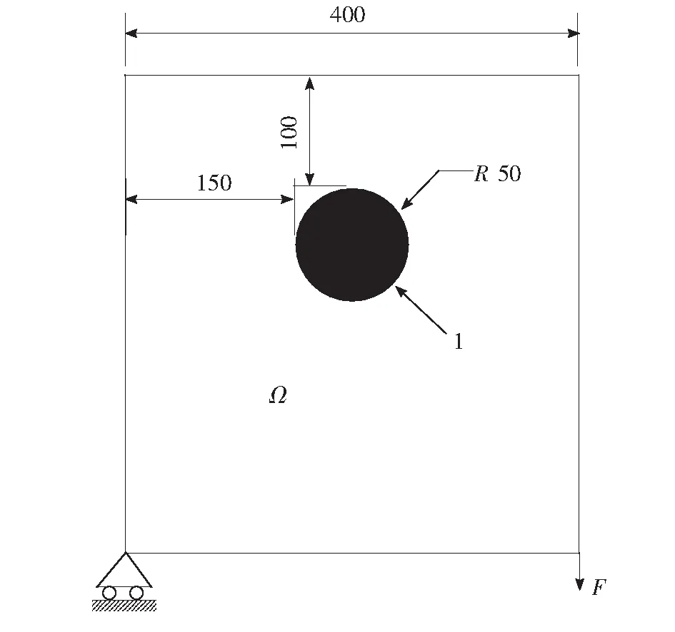
Fig.3 Design area and boundary conditions
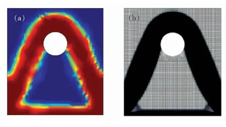
Fig.4 (a) Topological optimization results based on non-smooth inequality contact conditions. (b) Topological optimization results based on smooth equation contact conditions.
We next took the plane mirror model shown in Fig.5 as an example to establish the contact topology optimization model. In the figure, the red area is the optimized design area, boundary 1 is fixed, and the mirror is affected by gravity. The objective function is the minimum absolute value of thez-direction of the center point of the plane mirror. We analyzed the initial structure to obtain the negativez-direction of the center point of the plane mirror with the smallest possible objective function,Vmin=0.7,p=4. We used a hexahedral mesh and 131 100 triangular prism grids.
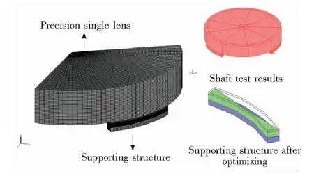
Fig.5 Topology optimization model of optical coupling force with nonlinear contacted for plane mirror
The initial value of the objective function was 35.3 nm; after optimization, it was 16.9 nm. The objective function, the absolute value of thez-direction of the center of the plane mirror, was reduced by 52.12% and presented significant optimization effect. The iterative process graph is shown in Fig.6.
The absolute value of thez-direction displacement of the center point of the planar mirror was reduced by 62.57%, the PV value was reduced by 14%, and the RMS value of the face was reduced by 13.8% in our experiment. After the optimization process and the accompanying change in volume fraction, we found that a larger volume fraction yields a smaller objective function, PV value, and RMS value.
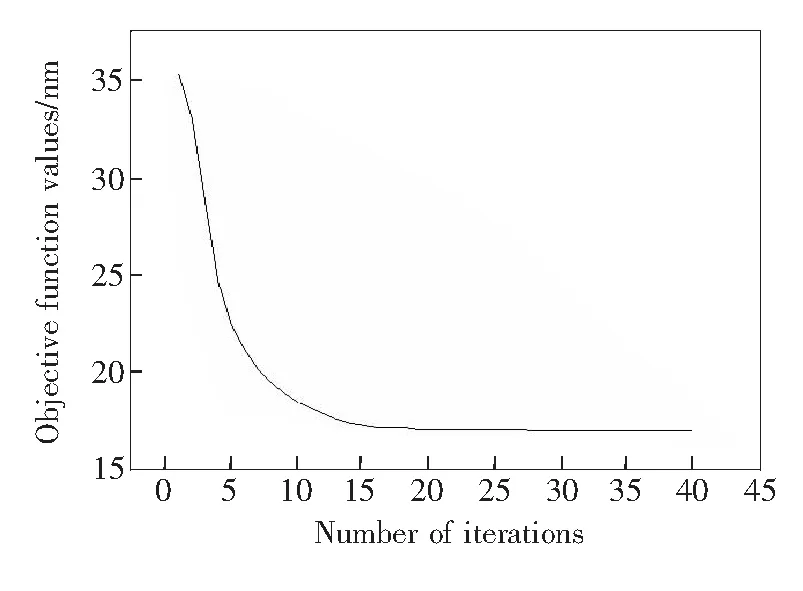
Fig.6 Iterative process graph
5 Experiments and Results
5.1 Experiment Setup
The experiment system for the precision single lens support is designed as Fig.7. A laser beam (650 nm wavelength, continuous irradiance mode semiconductor) propagates through a standard mirror, the designed precision single lens, reflector lens, and then is reflected and focused on the detector of interferometer(Zygo Corporation, diameter 102 mm, system resolution 1 024×1 024). The precision single lens is placed on the designed support structure. This experimental setup can be measured to optimize the design of the support structure after the precision single lens accuracy.
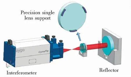
Fig.7 Experiment setup for the precision single lens support
5.2 Results and Analysis
The results of theN-step rotation averaging method are shown in Fig.8. Fig.8(a) and Fig.8(c) are the results after structural optimization while Fig.8(b) and Fig.8(d) are the results before optimization. The plane mirror surface PV values before optimization were 32.685 nm and 34.964 nm, and the RMS values were 4.976 nm and 6.015 nm, respectively. The suplane mirror surface PV values after optimization were 12.958 nm and 19.794 nm, and the RMS values were 1.279 nm and 3.676 nm, respectively. The plane mirror surface PV values decreased by 60.4% and 42.9%, and the RMS values decreased by 74.3% and 38.9%. The detailed measurement results are listed in Tab.1.
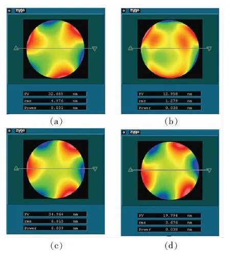
Fig.8 Interferometer measurement results for precision single lens

Tab.1 Before and after structural optimization: result analysis
6 Conclusion
This paper presented a novel topology optimization design for precision single lens support. A contact topology optimization model with optical aberration PV value as target was established, then used to design and optimize a high precision single lens. An experimental platform was set up and used to further analyze the effectiveness of the proposed model. The plane mirror surface PV value and RMS value were obtained after applying the proposed supporting structure. The plane mirror surface PV values decreased by 60.4% and 42.9%, and the RMS values decreased by 74.3% and 38.9% after structural optimization. These results suggest that the proposed method has very strong potential for practical application.
Acknowledgments: The authors would like to thank Tao Wang for the assistance rendered with the mechanical adjustment stage and appreciate useful discussions with Hai Yu of CIOMP.

