Numerical analysis of reactive turbulent flow in the thrust chamber of RD-108 engine rocket
Seyed Reza Taghavi,Mohammad Ali Dehnavi,Ali Ghafouri
Department of Chemical Engineering,Imam Hossein Comprehensive University,Tehran,Iran
Keywords:Liquid propellant engine Computational fluid dynamics(CFD)Kerosene and oxygen Freeze model Finite rate chemistry model
A B S T R A C T Combustion chamber modeling and simulation of the liquid propellant engine with kerosene as fuel and liquid oxygen as an oxidizer in the turbulent flow field are performed by CFD technique.The flow is modeled as Single-phase in steady state and using RNG k-3turbulence model.Simulation results are validated by experimental data of thrust, special impulse and combustion chamber pressure. By comparing two reaction models of finite rate chemistry and frozen model with experimental data,it is concluded that finite rate chemistry has acceptable results.The optimum value of equivalence ratio(oxidizer to fuel ratio)per reaction and operational parameters of the engine which maximize thrust and special impulse are determined.
1. Introduction
A liquid propellant rocket engine is a kind of rocket engine that uses chemical substances(liquid propellant)as energy and working fluid.In a liquid rocket engine,liquid propellant(fuel and oxidizer)reacts in the chamber and produce high-pressure gas which exhausts from the nozzle to make thrust[1].Liquid propellant rocket engine includes a thrust chamber(injector,combustion chamber,and nozzle)propellant feeding system,fuel and oxidizer tanks and various automatic regulators[2,3].The combustion chamber is occupied for mixing then combustion of propellant(as a reactor liquid propellant feed include fuel and oxidizer)based on the third law of Newton,nozzle causes to increase velocity of hot products to ultrasonic velocity and thrust.The final purpose of a rocket engine is converting potential energy of liquid propellant to kinetic energy[2—4].Design and developing of such engines are costly and timeconsuming experiments. Nowadays modeling and numerical simulation are developed to improve the efficiency of experiments.In other hand validation of numerical simulation results by experimental data and predictability of numerical simulation for beyond data range is the challenge of scientists[5].
De Giorgi,Sciolti[6]investigated probability density function(PDF), flamelet and eddy dissipation approach of combustion models by two various chemical kinetic of Jones-Lindstedt(JL)and Skeletal(SKEL)to simulate Methane and Oxygen at high pressure and temperature.Then compared model results by empirical data and concluded that eddy dissipation approach by the reduced kinetic mechanism of JL has better results,good approximation in temperature peak and flame shape and low computational cost.They used the k-3model to flow turbulence and Peng-Robinson and Soave-Redlich-Kwong for thermodynamic properties. Garg,Sharma[7]used numerical modeling of kerosene and oxygen combustion and showed that thermodynamic properties of gas products of combustion have a deviation from ideal conditions and real gas model of Soave-Redlich-Kwong cubic model closely estimates empirical data. They used the non-premixed model by chemical equilibrium for chemical reaction and(SST)k-ε for turbulent flow modeling.Banuti,Hannemann[8]developed a thermodynamic model of multi-fluid for the thermodynamic behavior of flow with reaction modeling in the liquid propellant engine which real gas behavior is considered just for cryogenic oxygen and other species are considered ideal gas.This model causes to reduce computational cost and corresponds with experimental data.Li,Ge[9]modeled mixing and combustion of the jet engine includes kerosene and hydrogen peroxide on a laboratory scale by Eulerian-Lagrangian discrete phase model.They used the Peng-Robinson thermodynamic equation to modeling real gas and flamelet to combustion modeling.Kang and Sung[10]studied the characterization of dynamic combustion of kerosene and layered GOxmixture with supercritical conditions by flamelet model and real gas equations of Redlich-Kwong Peng-Robinson.Nguyen,Popov[11]investigated long duration instability of combustion of liquid propellant rocket engine by applying RANS/LES multi species compressible flow and flamelet model for turbulent combustion and attained acceptable prediction of experimental results.
Nomenclature
A pre-exponential factor
Cpspecific heat capacity at constant pressure
Cξvolume fraction constant
Di,mdiffusion coefficient of ith component in the mixture DT,ithermal diffusion coefficient
E energy of the system
Eaactivation energy
Gbturbulent energy produced due to the buoyancy force
Gkturbulent energy produced due to mean velocity variation
h enthalpy
Jidiffusion flux of the ith component
k turbulent kinetic energy
K fluid thermal conductivity
Keffeffective conductivity coefficient
Ktturbulent conductivity coefficient
M molecular weight
Mtturbulent Mach number
p pressure
R universal gas constant
Rinet rate of the ith component generation
Sctturbulent Schmidt number
Shvolumetric heat sources
T Temperature
Yimass fraction of ith component
YMexpanding fluctuation in the compressible turbulence
α speed of sound
αkinverse effective Prandtl numbers for k
αεinverse effective Prandtl numbers for ε
γ adiabatic constant
ε dissipation rate of turbulent kinetic energy
μ dynamic molecular viscosity
μtturbulent(or eddy)viscosity
μeffeffective viscosity
υ kinematic viscosity
ξ*length fraction
ρ density
τ stress tensor
τ*reaction time scale
υ velocity
φ equivalence ratio
Kinetic mechanism is used in the numerical simulation for combustion analysis which includes numerous species and single step reactions that relates to computational cost.Zeng,Liang[12]used single step and new mechanism(210 reactions and 50 species)of reactions and found that single step is not able to consider the effect of intermediate species and a new mechanism for combustion has good agreement with empirical data.Choi[13]introduced 9 steps reduced mechanism of kerosene combustion which includes chain reactions.Yang and Sun simulated kerosene and liquid combustion by 16 step reaction mechanism, eddy dissipation model,k-ε turbulence model in three dimensions[3].Mardani et al.simulated liquid and solid propellant chamber and nozzle to investigate the effect of various parameters on operational conditions by two models of freeze flow and finite rate from CEA code,k-ε turbulence and eddy dissipation model in two dimensions and symmetric conditions.The results of these researches have good agreement with empirical data[14].
In order to analyze turbulence and dynamics of flow Xiao,Tsai[15]verified a compressible jet plume of over expanding nozzle with RANS equations and some turbulence models.Comparison of experimental data and simulation results showed that two equation shear stress model has the best result.Urbano,Selle[16]simulated combustion instability of liquid propellant engine by large eddy simulation model.Balabel,Hegab[17]stated shock position and pressure level of behind shock prediction are related to turbulence model.They concluded that(SST)k-ε have the best results in wake point and determining shock wave.Mardani et al.used eddy dissipation concept to relate chemical reaction and turbulence,k-ε turbulence model and reduced and detailed combustion mechanism. They investigated turbulence effect on reaction rate and molecular diffusion on combustion regime and concluded that diffusion phenomena should be considered in two mechanism and it is not negligible versus bulk flow.Temperature fluctuation and species concentration effect on the flow field inappropriate turbulence interaction and chemical reaction cause error in flame temperature prediction[18,19].Geatz[20]developed computational code for thrust performance index of asymmetric two-dimensional convergence-divergence nozzles and stated that thrust coefficient calculation by code has a good agreement by experimental data.They concluded that compatibility of the k-ε turbulent model with EDC in two-dimensional systematic geometry[3,8,14].
In the simulation strategy,the thrust chamber is divided into two main zones near the injector and downward injector[21].The main problem is modeling of near injector zone is unable to measure size and distribution of generated particle by injector elements[22].The major works done in this field are categorized in nonhomogenous models which trace single droplets or droplet group to spray modeling(Eulerian-Lagrangian approach)[23]and homogenous multi-phase model that fluids are adjacent medium with no velocity and heat delay between phases[22].While in the downward injection zone, fluids turn to vapor and it mixed completely,then vapor exited from the nozzle to make thrust.In downward injection zone spray,breakup and droplet accumulation effect are not considered and the system is a homogenous mixture of combustion products and non-reacted materials are considered as the gas phase.
As it is evident in the previous studies,the effect of the equivalence ratio on the performance of liquid propellant engine has been investigated in general,but the effect of reaction rates,temperature,reaction heat and mechanisms,reaction chains priority,reaction zone and distribution of species on the liquid propellant engine performance is not studied quantitatively.So in this paper,the effect of equivalence ratio on the liquid propellant engine performance by considering temperature,mechanisms,reaction zone and distribution of species have been studied numerically.First,the RD-108 liquid propellant engine was simulated by two common models of finite-rate and freeze,then,the effect of the mechanism in various equivalence ratios is studied by numerical solution of reactive turbulent flow to analyze combustion reaction mechanism effect on the distribution of species,side reactions,flow dynamics,temperature and pressure distribution and performance of the RD-108 liquid propellant engine. Finally, the optimum equivalence ratio is obtained for the RD-108 liquid propellant engine.
2. Experimental model
In this research modeling and simulation are based on experimental data of RD-108 engine.The combustion chamber of the RD-108 engine configuration is illustrated in Fig.1[24].The data of the experimental test in vacuum condition for two similar systems of liquid oxygen and kerosene with constant flow and equivalence ratio are expressed in Table 1[25].
3. Numerical modeling and simulation
The purpose of system modeling is stated in a mathematical equation for the characterization of momentum,mass and heat transfer.The simulation is performed by commercial computational fluid dynamics(CFD)code(ANSYS Fluent 15).
3.1. Governing equations
Flow,species,energy turbulence and auxiliary equations are solved simultaneously by the numerical method of combustion modeling[1].Continuity(1),momentum(2)and heat transfer equations(3)—(6)are as below:

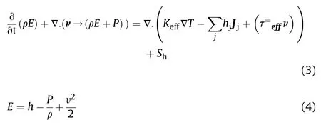

Keffis effective conductivity coefficient,Ktturbulent conductivity coefficient,K fluid thermal conductivity,hjenthalpy of j and Jiflux of j.In energy equation,Shis heat transferred to the system by heat sources such as heat of reaction and the three terms remaining in the right side of the equation are condensation,species,diffusion and dispersion due to gravity.The term E,is the energy of the system and includes sensitive enthalpy h(due to internal energy)and energy of pressure and velocity.RNG k-ε turbulence model as considered by comparing the precision of results and computational time.In the RNG k-ε model,turbulent flow is interpreted with k and ε parameters.Equations(7)-(13)are used to calculate these parameters.
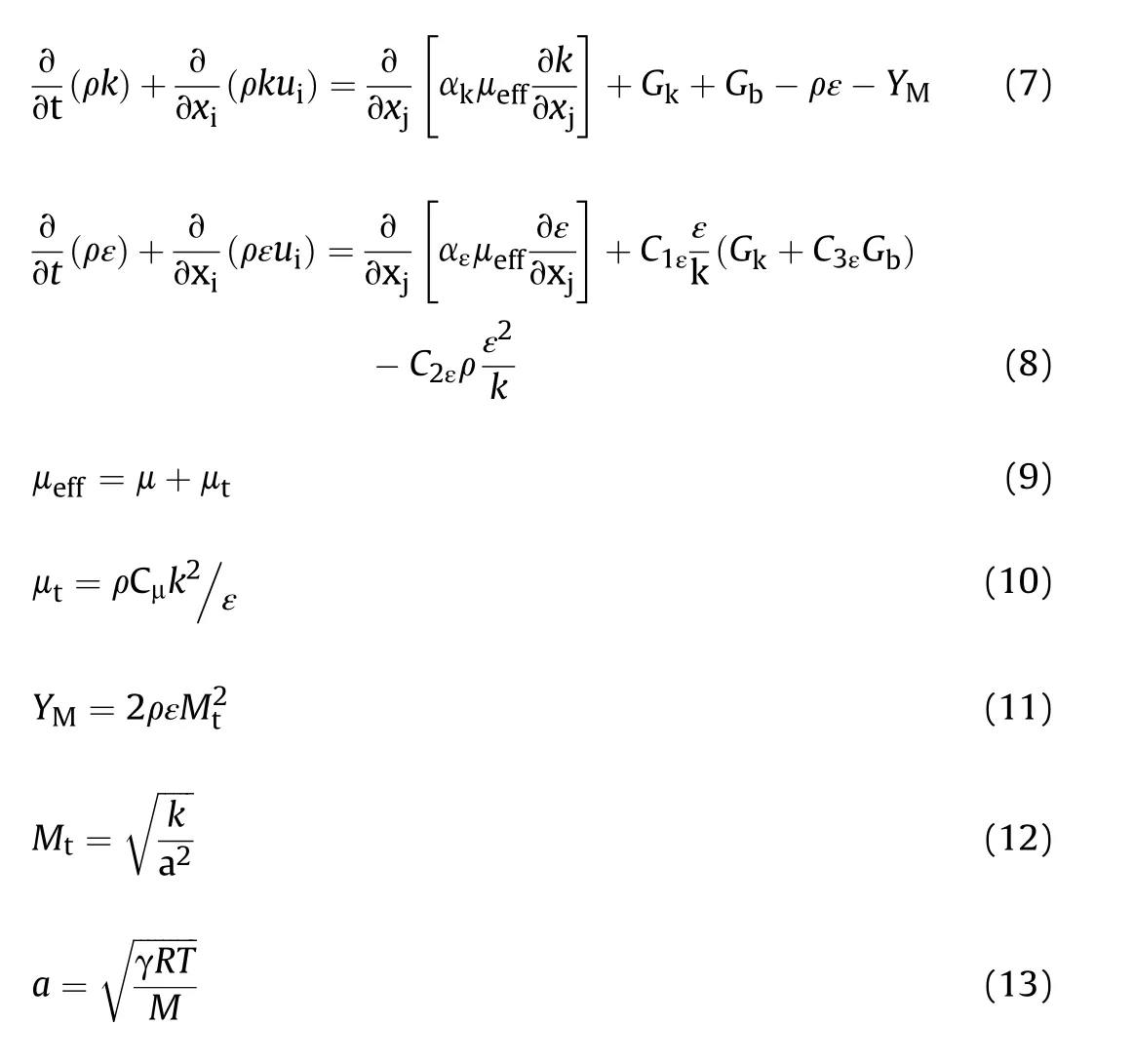
k is turbulent kinetic energy,ε,dissipation rate of turbulent kinetic energy,Gk,the turbulent energy produced due to mean velocity variation,Gb,turbulent energy produced due to buoyancy force and YMexpanding fluctuation in the compressible turbulence.αk,αε,C1ε,C2εandare modeling constants(Table 2).

Fig.1.The geometry of RD-108 engine used in the simulation.

Table 1 Operational parameters of RD-108 engine used in the simulation.
Species equation predicts the mass transfer of combustion components.Species transfer and Fick diffusion of turbulent flow for gas expression are converted to equations(14)and(15)as below:

Which Yiis the mass fraction of the ith component,Jidiffusion of ith component and Ri,the net rate of ithcomponent generation or consumption.Di,mis diffusion coefficient of ithcomponent in the mixture, DT,iheat diffusion coefficient (thermal coefficient), T temperature,μtturbulent viscosity and Sctturbulent Schmidt number.Sctof equations is 0.7 and Riis modeled by finite rate model which is related formulation to kinetic and flow turbulence.Arrhenius equations are applied in the finite rate model whereas flow turbulence is not considered in kinetics of reaction.Turbulent flow is not considered in this model but in the eddy dissipation model(EDM)reaction rate is affected by turbulence.The improved approach of EDM(eddy dissipation concept)is used and equations(16)-(18)describe EDC[26,27].Finite rate and freeze model approaches have low computational cost to simulate hot flow in the combustion chamber and nozzle of the engine[14].
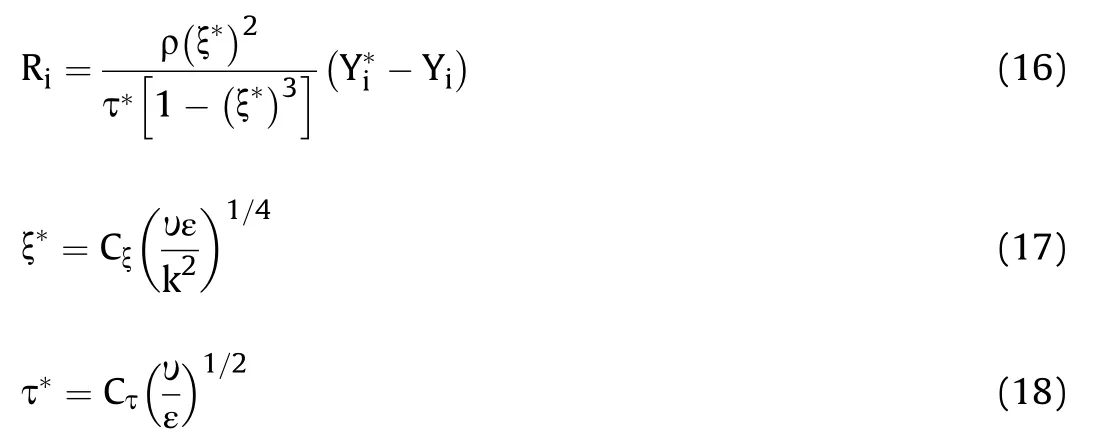
ξ*is length fraction of the fine scale,τ*reaction time scale,mass fraction of i-component after reaction at τ*,υ kinematic viscosity,k turbulent kinetic energy,ε turbulent kinetic energy dissipation rate and Cξ is volume fraction constant with the magnitude of 2.1377.
3.2. Numerical simulation
The equations are solved by the finite volume method.In this research,domain is considered two dimensional and injector surface effect in the spray system is not considered.Because of a large amount of computations,the combustion reaction is considered insteady state and axial symmetric chamber.Second order upwind method to the discretization of equations and pressure velocity coupled method are used in the simulation.The Courant number of simulation is considered 103.The computational time for simulations based on the finite rate approach is 40 min and simulations based on the freeze approach are 200 min.

Table 2 The values of modeling constants.
3.3. Initial and boundary equation
Based on the operational condition in vacuum test,pressure outlet is applied to all outlet boundaries,rotation axis for the symmetric axis of the system,mass flow inlet for inlet flow and wall for all solid boundaries with a constant temperature of 700˚k are considered as boundary conditions.Mass flow inlet is 76.155 kg/s and chemical composition of inlet flow are specified by HP module of chemical equilibrium composition and application(CEA)software.Temperature and the molar fraction of combustion resulted from CEA are occupied as inlet boundary condition.Inlet boundary conditions for various equivalence ratios are showed in Table 3.
3.4. Grid independence
Independence of solution from geometry grid is investigated by 3 type of structured mesh sizing with 4200,13620 and 35430 element air as fluid and same conditions.Radial velocity of nozzle outlet and axial Mach number along to chamber axis are two parameters considered to analyze grid independence.
Fig.2 shows that a medium mesh-size result has no difference with fine but has a significant difference from the coarse grid.So medium mesh-size is selected as the desired grid to simulation.
4. Results and discussion
4.1. Freeze and finite rate model
Freeze and finite rate model are used to simulate the hot flow of solid and liquid thrust chamber.Complete reaction of fuel and oxidizer is assumed in freeze approach and there is no component change in the combustion chamber.In other words,in this type of simulation,the products do not react again.The reaction of inlet species in the finite rate approach is due to thermodynamicvariation of inlet flow and the reaction rely on species.
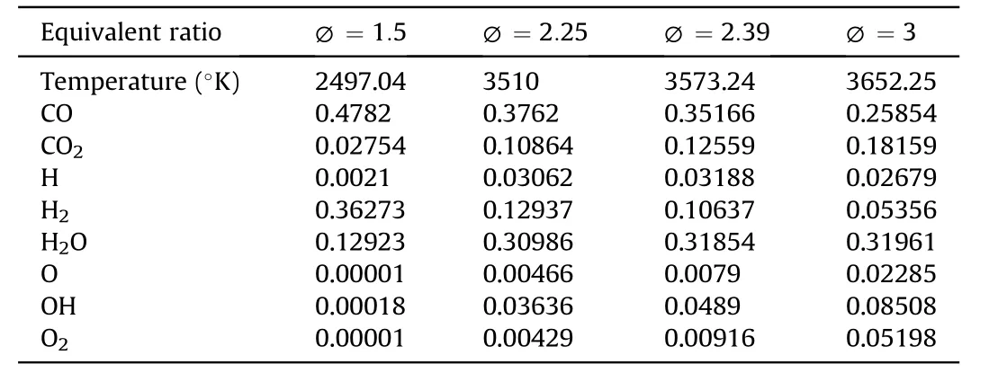
Table 3 Combustion products in various O/F and 50.663 bar chamber pressure by CEA.
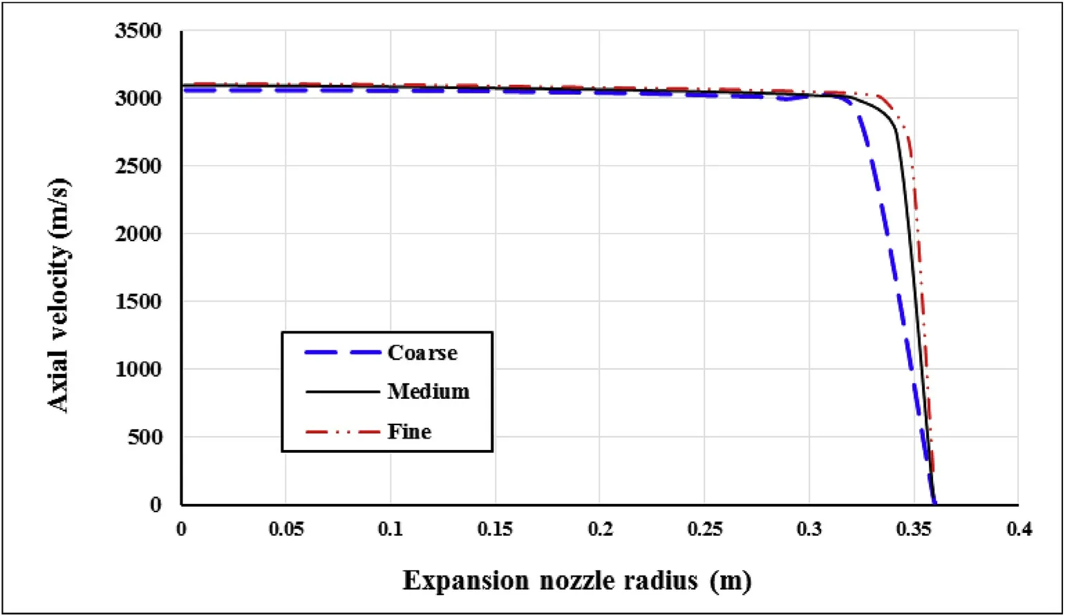
Fig.2.Axial velocity of nozzle exhaust used for grid independence.
In this article,thrust chamber simulation is performed by freeze and finite rate approaches,then the results are validated with experimental data and parameters of the simulation are analyzed.Reduced mechanism of Choi for kerosene and oxygen combustion is applied to simulation(Table 4)[12,13].
Reaction rates are calculated by Arrhenius equation(k(T)=Table 5 shows thrust, special impulse and chamber pressure results of freeze and finite rate models.
Combustion simulation error is in the acceptable range,so the models can use to analyze the same cases.Finite rate model which effect of the downward combustion chamber and exhaust nozzle is considered has more agreement to experimental data than freeze model.Fluid velocity charge of nozzle exhaust in terms of expansion nozzle radius(Fig.3),total temperature and absolute pressure charge in terms of symmetry axis length of the domain(Fig.4)are illustrated to simulation parameters of finite rate and freeze model comparison.The dependency of parameters in the finite rate model differs from freeze model.Reaction rate,flow turbulence,temperature and pressure effect on each other in finite rate model.Absolute pressure predictions along the symmetry axis of the engine and axial velocity versus nozzle exhaust radius have no considerable difference in the models.Finite rate model shows more pressure than freeze model from the beginning of chamber zone until 0.7 m distance(includes chamber and throat)which it is due to species reaction and effect of reaction on thermodynamic properties.It is concluded that additional reactions in the system are fromthe chamber to the throat zone,but in the divergence section of the nozzle,reactions are not sensible.
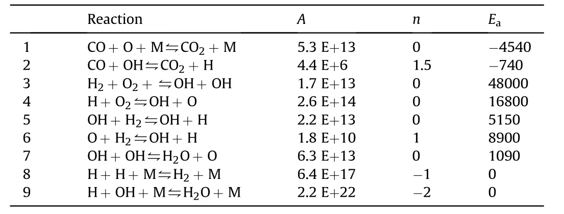
Table 4 Reduced mechanism for kerosene and oxygen combustion(units cm3,mol,s,kcal,K)[13].
Finite rate model results show a sudden temperature increase in the inlet of the combustion chamber and nozzle zone(Fig.4).Because of the high concentration of reactants in the chamber inlet,the reaction rate is high while in the nozzle zone pressure decreases and it is expected reaction develops toward increasing mole number and complete reaction of kerosene.Stagnation temperature decrease for freeze model is due to heat transfer flow with nozzle casing.Velocity contour of finite rate and freeze models are showed in Fig.5.The central bulk of fluid velocity in finite rate model is a slightly more than freeze,so nozzle outlet axial velocity(Fig.3),thrust and special impulse(Table 5)difference rate are vindicated.It could be expressed that difference is caused by a reaction in finite rate model,then gas temperature increases due to reaction heat(Fig.4),after that more expanding of gases and finally kinetic energy and velocity are increased.
4.2. Equivalence ratio on system parameters
Equivalence ratio(∅)and species composition are considered based on Table 3 and inlet boundary conditions for each equivalence ratio are temperature and species composition.Static pressure on axis(r=0)in various equivalence ratios are specified in Fig.6.The chamber pressure of ∅=2.25 is maximum(chamber pressure varies between 5.7 and 6.3 MPa).In all of the equivalence ratio predicted pressure of finite rate model is more than freeze model.
Variation of static temperature on engine axis for finite rate and freeze model in equivalence ratio is illustrated in Fig.7.If entropy is assumed constant,it could be concluded that pressure decrease of expanding process cause to temperature decrease.Based on Fig.7 and Table 3,if ∅increases then inlet temperature will increase.
Because of heat reactions,the predicted static temperature of finite rate is more than freeze in all ∅ranges and the temperature difference is more sensible by equivalence ratio increasing.Static temperature increasing of finite rate model at the beginning of the combustion chamber is due to reaction then temperature decreases slowly.This trend is more obvious in ∅=3.In all equivalence ratios,temperature decrease becomes faster because of fluid velocityincreasing in the nozzle.

Table 5 Comparison of simulation results by corresponding experimental data.
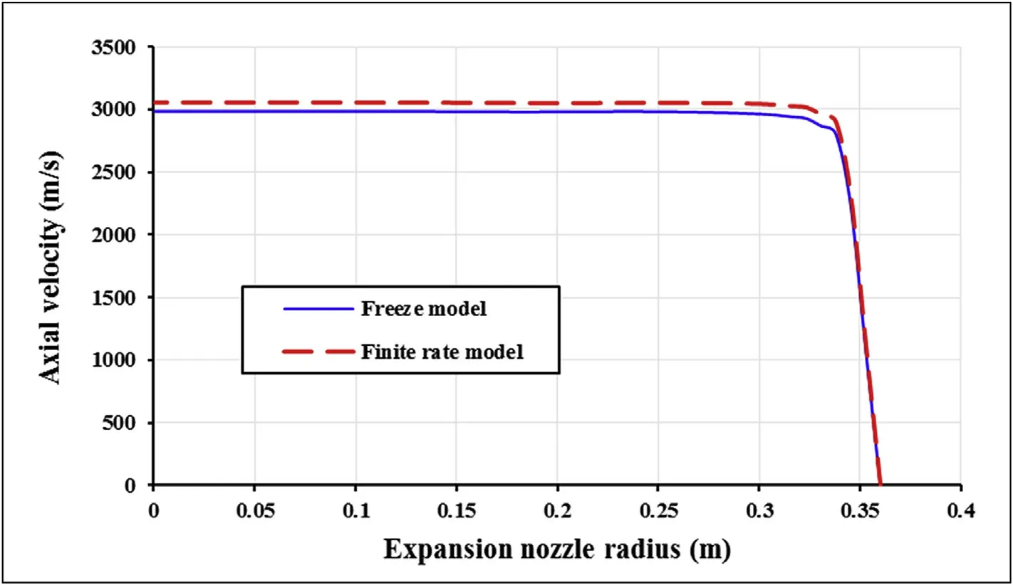
Fig.3.Velocity change versus expansion nozzle radius.
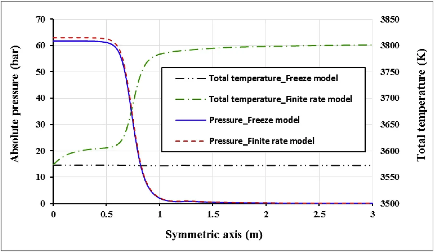
Fig.4.Pressure and temperature change along with the symmetric axis of the engine.
Sudden decrease of flow velocity due to transfer from shock wave is observed in the divergence zone of nozzle cause static temperature increasing.
Total temperature or stagnation temperature changes for finite rate and freeze models are shown in Fig.8.Based on Fig.8 temperature change for equivalence ratios of 1.5,2.25 and 3 in freeze model have the same trend because in the isentropic process,if there is no heat source,stagnation temperature and enthalpy of the process become constant.There is slightly loss of temperature along nozzle.Since the pressure does not affect the temperature of this model,so temperature decrease is due to heat loss from walls.
According to the stoichiometry of kerosene and liquid oxygen reaction.In the convergence zone of nozzle pressure decrease cause to complete the reaction and more generation of products,while in∅=3,first stagnation temperature increases,then tend to rise as the same as ∅=1.5 and ∅=2.25.
Reaction rate changes to reactions of Table 4 for finite rate model in various equivalence ratios which are shown in Figs.9—11.The reaction rate is increased by equivalence ratio increasing.All of the reactions are completed before than x=0.65.Chain reactions are a series of reactions that tend to the final product and are classified as propagating and terminating reactions.According to Table 4,reaction number 1,8 and 9 are terminating and the rest of the reactions are propagating.Propagating reaction priority is based on reaction rate constant,which it is a function of temperature.
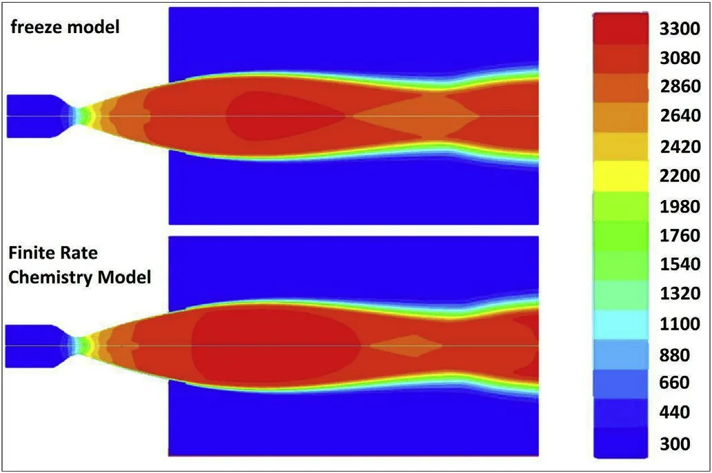
Fig.5.Velocity contours of freeze and finite rate models.
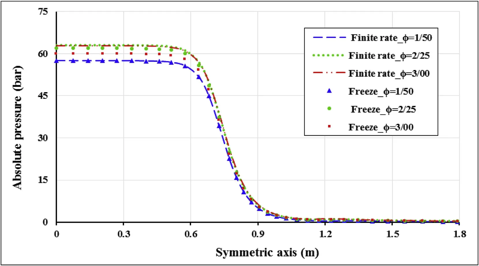
Fig.6.Static pressure change along to the symmetric axis of the engine.

Fig.7.Static temperature change along to the symmetric axis of the engine.
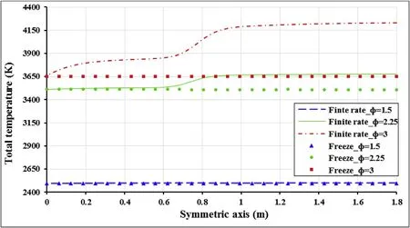
Fig.8.Total temperature change along to the symmetric axis of the engine.
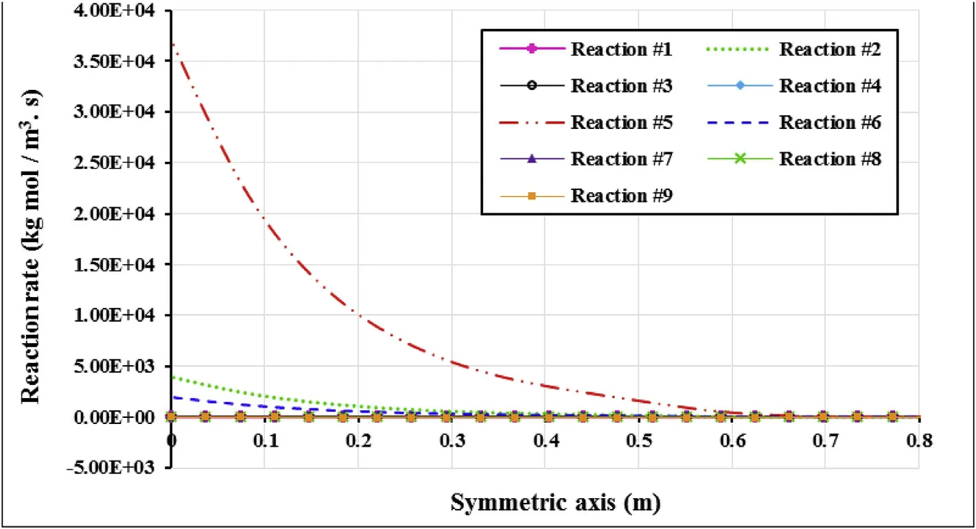
Fig.9.Reaction rate change along with the symmetric axis of the engine(∅=1.5).
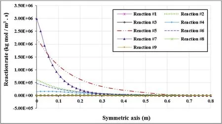
Fig.10.Reaction rate change along with the symmetric axis of the engine(∅=2.25).

Fig.11.Reaction rate change along with the symmetric axis of the engine(∅=3.5).
The first priority of reactions is reaction number 7 and the last one is reaction number 3.As it is obvious,the reaction rate variations of equivalence ratios are too low and they are affected by other reactions.So they could be negligible.Figs.9—11 show that the reaction rate trend of 2.25 and 3 equivalence ratios are the same and differ from ∅=1.5.This is because of species condition and temperature of inlet flow.If OH radical is assumed as limiter then reactions of number 7 and 5 are identified as a key propagating reaction.So they could be considered as starting of chain reaction which generates CO2and H2O.O radical of reaction number 7 reacts with H2of reaction number 6 and generates H and OH radicals.Based on reaction number 2,OH radical reacts with CO and generates CO2and H.In the second chain reaction H2O and H are generated from reaction number 5.This reaction has a higher priority than reaction number 7 in equivalence ratio of 1.5.These reactions are competing for each other in ∅= 2.25, while in equivalence ratio of 3 reaction number 7 is preferred.Graph slope and reaction rate trend of chain reaction prove this analysis.Among the propagating reactions,H consumption priority is for reaction 4.In equivalence ratio of 1.5,the inlet flow of raw materials has a little O2and H.So the rate of reaction number 4 is very low.While H magnitude of inlet flow increases in larger equivalence ratio and it causes increasing of the reaction rate of number 4 in the beginning zone.Then in equivalence ratio of 2.25 reaction numbers of 5 and 6 generates H radical,when the generation rate of H is uniform.The slope of reaction rate number 4 is uniform and become descending by finishing O2.In ∅=3,reaction number 7 has first priority but the inlet flow of H2in reaction 6 is finished by decreasing H2content.In spite of the content of O2,reaction number 4 first goes up then fall and finally finished.
Figs.9—11 show that mean reaction rate of equivalence ratios of 2.25 and 3 is 1000 times of reaction rate in ∅=1.5.This is because of low reaction potential of species in inlet flow of ∅=1.5.Variation of species mole percent along to the chamber in the finite rate model is showed in Fig.12.CO content in the outlet of the nozzle shows incomplete burning. If the equivalence ratio becomes greater,the reaction rate of kerosene tends to completion.In other words,the main products of H2O and CO2become more than CO in the outlet of the nozzle.It is necessary that reactions 1 and 2 have maximum progress to maximize the generation of CO2and also CO content should be consumed.To develop reactions of 1 and 2,O and OH should increase in the chamber.By rising equivalence ratio,O and OH content of inlet increases,also the inlet temperature of chamber goes up which affects reaction priority.
Priority of reaction number 2 decreases by temperature increasing but by the preference of reaction numbers 4 and 7,OH content of chamber become larger that cause more Co consumption in reactions.In φ=1.5,the mole fraction of species are constant and so it shows that species of inlet flow don't react.
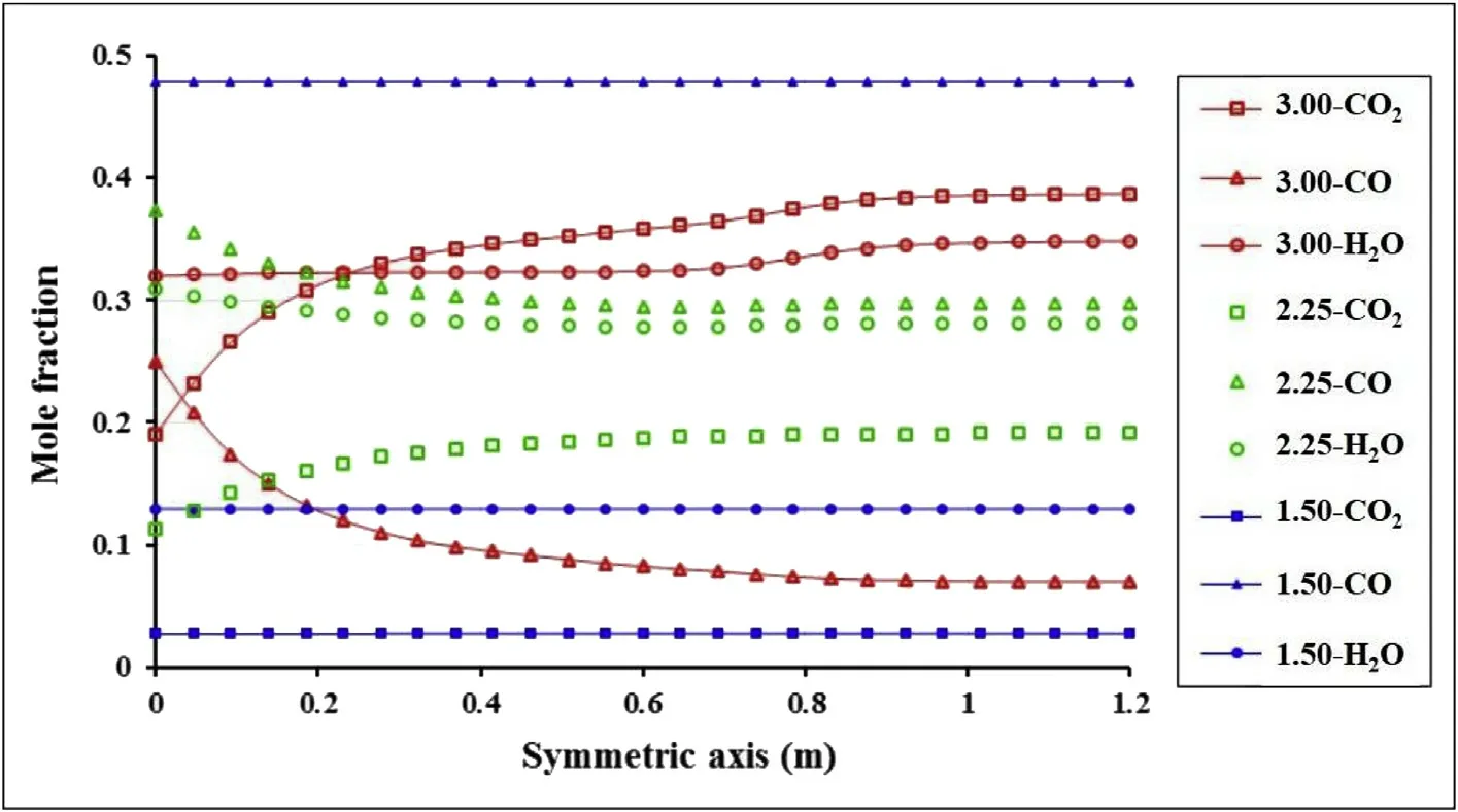
Fig.12.Mole fraction of H2O,CO2,and CO along to the symmetric axis.
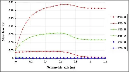
Fig.13.O and H radical species change along to the symmetric axis.

Table 6 Thrust and special impulse of various equivalence ratios in the finite rate model.
Variation of O and H radicals along to the chamber to the nozzle outlet is investigated in Fig.13.Radicals are very much in ∅=3 which proves a sudden temperature increase of Figs.7 and 8.Because radicals cause temperature increases.If ∅is greater,O and H radicals are increased.This is because of reactions 5 and 7 priority and their related path of a chain reaction.By increasing O in ∅=3,reaction rate of number 7 then reactions 4 and 6 become larger to complete reaction due to reaction number 2 which cause increasing H but in ∅=2.25 reactions 5 and 7 compete with each other while the reaction chain is shorter than equivalence number 3 to reaction 2 and H of system is decreased.As figures show,most of the reactions occur before the nozzle but along with the nozzle reactions of ∅=2.25 and ∅=3 are occurred slowly and tends to equilibrium.
According to Table 6 and Fig.14,thrust and special impulse are first increased then decreased by equivalence ratio rising.So it is concluded that there is an optimum oxidizer to fuel ratio for each engine which thrust and special impulse are maximized.
5. Conclusion
Simulation of an RD-108 rocket engine with liquid oxygen and kerosene RP-1 is performed by freeze and finite rate models and reduced mechanism.The results of thrust,special impulse and chamber pressure are validated by experimental data.The results have 3—20%deviation from data which is an acceptable deviation.Simulation results of finite rate model have a good agreement to experimental data.Various operational parameters such as pressure change,stagnation temperature,reaction rates and species composition in equivalence ratio of 1.5,2.25 and 3 are simulated.The results show that in the same inlet flow,it could improve the operational properties of the engine by changing the equivalence ratio and it causes reaction completion.While key parameters such as thrust and special impulse have optimum value based on equivalence ratio for the RD-108 engine.Most reactions are in the combustion chamber but some of them tend to equilibrium slowly by passing through the nozzle.
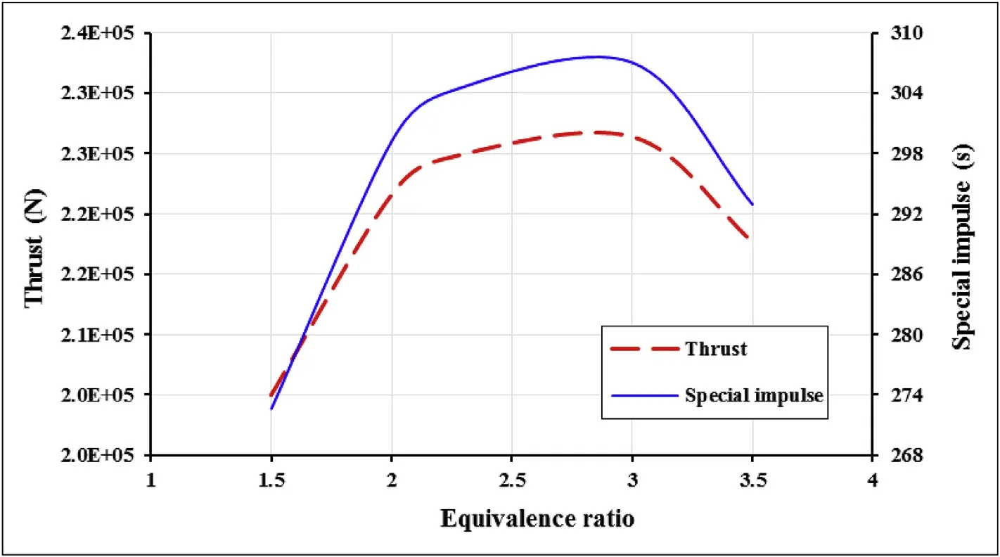
Fig.14.Equivalence ratio effect on thrust and special impulse.
- Defence Technology的其它文章
- Modeling on the shock wave in spheres hypervelocity impact on flat plates
- Insensitive high explosives:IV.Nitroguanidine—Initiation&detonation
- Effect of energy content of the nitraminic plastic bonded explosives on their performance and sensitivity characteristics
- Effect of wave shaper on reactive materials jet formation and its penetration performance
- A comparative study for the impact performance of shaped charge JET on UHPC targets
- The role of crystal lattice free volume in nitramine detonation

